Single high-energy arc proton therapy with Bragg peak boost (SHARP)
Abstract
Introduction
Because of the co-location of critical organs at risk, base of skull tumours require steep dose gradients to achieve the prescribed dosimetric criteria. When available, proton beam therapy (PBT) is often considered a desirable modality for these cases, but in many instances, compromises in target coverage are still required to achieve critical organ at risk (OAR) tolerance doses. A number of techniques have been proposed to further improve the penumbra of PBT. In the current study, we propose a novel, collimator-free treatment planning technique that combines high-energy shoot-through proton beams with conventional Bragg peak spot placement. The small spot size of the high-energy pencil beams provides a sharp penumbra at the target boundary, and the Bragg peak spots provide a higher linear energy transfer (LET) boost to the target centre.
Methods
Three base of skull chordoma patients were retrospectively planned with three different PBT treatment planning techniques: (1) conventional intensity-modulated proton therapy (IMPT); (2) high-energy proton arc therapy (HE-PAT); and (3) the novel technique combining HE-PAT and IMPT, referred to as single high-energy arc with Bragg peak boost (SHARP). The Monaco 6 treatment planning system was used.
Results
SHARP was found to improve the PBT penumbra in the plane perpendicular to the HE-PAT beams. Minimal penumbra differences were observed in the plane of the HE-PAT beams. SHARP reduced dose-averaged LET to surrounding organs at risk.
Conclusion
A novel PBT treatment planning technique was successfully implemented. Initial results indicate the potential for SHARP to improve the penumbra of PBT treatments for base of skull tumours.
Introduction
Due to the proximity of surrounding critical organs at risk (OARs), proton beam therapy (PBT) is often considered a desirable modality for base of skull tumours such as meningioma, chordoma and chondrosarcoma. However, within our institution's proton-to-photon comparative planning service, it has been noted that in some circumstances conventional radiation therapy with X-rays (XRT) may have a sharper high-dose fall-off than intensity-modulated proton therapy (IMPT). This means that target coverage may be marginally improved with XRT relative to PBT if adhering to tolerance doses of OARs in close proximity to the target volume. In this situation, the clinician must choose between a treatment modality that may achieve marginally superior target coverage and one that significantly reduces integral radiation dose to healthy tissues.
Beam apertures are one means of improving the high-dose fall-off of PBT. Beam apertures were essential patient-specific devices in passive scattering and uniform scanning delivery systems and have also been considered for intensity-modulated pencil beam scanning systems.1 Disadvantages of static beam apertures include increased cost of consumables per patient, radioactivation of the aperture resulting in radiation safety implications, including handling and storage, and the fact that the beam apertures only act on the largest field extent (rather than at each energy layer).
Other means of sharpening the PBT dose fall-off include multi-leaf collimators2, 3 and beam trimmers.4, 5 The advantages of these systems are that they reduce per-patient costs, increase workflow efficiency by not requiring the therapist to enter the room between fields and allow beam shaping on a per-energy layer basis. The disadvantages of these systems are increased upfront cost, increased system complexity (and in turn likelihood of triggering interlocks) and increased radioactivation build-up over time.
Multi-modality treatments combining PBT and XRT have been proposed to utilise the benefits of each treatment modality.6 However, there are significant logistical challenges in co-ordinating the required scheduling for different machines and reimbursement challenges in multi-modality treatments. In this scenario, one would ideally co-optimise the XRT dose distribution and the PBT dose distribution concurrently and deliver both modalities in the same treatment appointment.7 While a hybrid XRT-PBT system does not currently exist, there is the potential to make use of the PBT system to achieve the same objectives.
In the current work, we propose a novel PBT planning and delivery approach known as single high-energy arc with Bragg peak boost (SHARP). This concept combines a high-energy shoot-through proton arc with conventional Bragg peak intensity-modulated proton therapy (IMPT) beams. Because pencil beam spot sizes are smaller at higher beam energies, the high-energy arc component is used to shape the lateral penumbra, while the Bragg peak beams are used to boost the target volume interior. This concept also has the potential to result in higher dose-averaged linear energy transfer (LETd) towards the target interior, away from organs at risk.
Various alternative proton arc therapy (PAT) concepts have been previously proposed. Seco et al.8 investigated the dosimetric potential of passive scattering and IMPT proton arcs in the setting of non-small cell lung cancer, proposing that proton arcs have the potential to reduce the impact of range uncertainties in this tumour site. Sanchez-Parcerisa et al.9 and Bertolet and Carabe10 have proposed PAT techniques that made use of either single-energy or bi-energy proton arcs. Ding et al.11 and de Jong et al.12 have developed energy layer reduction algorithms incorporated within the PAT inverse optimisation routine to improve the delivery time of PAT. None of the previous PAT studies have proposed the use of small spot, high-energy shoot-through PAT with the goal of reducing lateral penumbra.
In this proof-of-principle study, three base of skull chordoma cases were replanned with (1) single high-energy proton arc-only beams (HE-PAT) and (2) the SHARP concept and compared with conventional IMPT treatment plans (BP).
Methods
Patient selection
Three patients with base of skull chordoma referred to our institutional comparative planning service were included in the study. Ethical approval for this work was covered by the Women's and Children's Hospital Network Human Research Ethics Protocol 2022/HRE00016.
Treatment planning objectives
Treatment planning was conducted in the Monaco treatment planning system (TPS) version 6.1.1.0 (Elekta AB, Stockholm, Sweden). A clinically accepted IBA Proteus®ONE (IBA, Louvain-La-Neuve) beam model was used. Treatment planning objectives were based on the chordoma consensus guidelines13 and eviQ guidelines.14 A prescription of 74 Gy RBE in 37 fractions with a constant RBE scaling factor of 1.1 was used. Table 1 summarises the OAR goals used for treatment planning.
| Organs at risk | Metric | Goal (Gy RBE) |
|---|---|---|
| Brainstem surface (outer 3 mm of brainstem) | D0.03cc | <6313 |
| Brainstem centre (remaining brainstem) | D0.03cc | <5013 |
| Optic nerve | D2% | 6013 |
| Optic chiasm | D2% | 6013 |
| Temporal lobe | D2cc | 7113 |
| Spinal cord surface (outer 3 mm of spinal cord) | D0.03cc | 6713 |
| Spinal cord centre (remaining spinal cord) | D0.03cc | 5513 |
| Cochlea | Mean | 4519 |
| Hippocampus | D40% | 7.320 |
| Hypothalamus | D0.03cc | 50 |
| Pituitary | Mean | 4520 |
| Eye | Mean | 3514 |
| D0.03cc | 5014 | |
| Retina | D0.03cc | 4520 |
| Lens | D0.03cc | 1019 |
Robust optimisation and evaluation of the CTV and serial OARs were employed. Geometric uncertainties of 0 and +/−3 mm and range uncertainties of 0 and +/−3% were included in the robust optimisation and evaluation. Combinations of these values resulted in 21 uncertainty scenarios being considered in both optimisation and evaluation. Both optimisation and evaluation were performed within the TPS.
Treatment plan optimisation attempted to adhere to primary OAR tolerance doses in all uncertainty scenarios. Target dose coverage was maximised while adhering to OAR tolerance doses.
Beam arrangement and spot placement
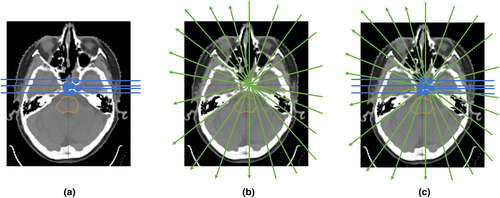
A conceptual comparison of the three different planning techniques is shown in Figure 1. Further details of each technique are provided below.
Conventional IMPT
Beam angles were selected to allow robust target coverage while avoiding ranging out on the brainstem as much as possible. Three fields were used for each patient where the gantry and couch angles selected were 80o, 80o, 70o and 0o, 180o, 270o for patient 1; 70o, 90o, 82o and 5o, 175o, 270o for patient 2; and 90o, 80o, 90o and 0o, 180o, 310o for patient 3, respectively. Note that the machine model was a half-gantry, requiring couch rotations for beams to be incident from opposing laterality.
Spots were placed with a 1 sigma lateral spot spacing and 1 sigma energy layer spacing with a 5 mm water equivalent distance (WED) distal and proximal margin and 8 mm lateral margin to the CTV.
HE-PAT
Single high-energy arc proton therapy (HE-PAT) plans were generated for comparative purposes only. Because the depth dose of a shoot-through proton beam is approximately constant with depth, many beam angles are required to avoid streaks of high dose outside the target volume. As is the case when comparing VMAT with 3DCRT, overlap of many beam doses at the target volume allows for a reduction in dose to OARs.
HE-PAT beams were arranged in 20° increments between gantry 0 and gantry 160°. A 20° increment was selected as a trade-off between a prolonged treatment time with many arc beams, and ensuring enough beams were used to allow for conformal dose distributions. For each beam, the TPS was used to generate spot placement with 0.8 sigma lateral spot spacing, 1 sigma energy spacing and the same target margins used in the conventional IMPT plan.
The energy layer in each beam with the largest number of spots was retained, and all other layers were removed. This energy layer selection occurred before any spot weight optimisation was performed, ensuring that the number of spots was dictated only by the geometry of the target volume in the beam's eye view, rather than also incorporating any removal of low-weight spots. The selected energy layer was manually changed to the maximum beam energy available with the system (226 MeV). This ensures that the proton pencil beam completely transits the patient and that a small spot size is present at the target volume. A smaller lateral spot spacing was used during the spot placement calculation for the HE-PAT beams to account for the smaller spot size at the higher beam energy.
SHARP
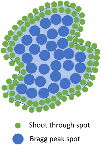
The SHARP approach is a combination of IMPT and HE-PAT. The ideal beam's eye view concept of SHARP is shown in Figure 2. To generate the SHARP plan in our TPS, the beams used in the HE-PAT plan were retained without change. The beams used in the conventional IMPT plan were also retained; however, the proximal, distal and lateral margins for spot placement were set to zero. This was done to force the optimiser to utilise the HE-PAT beams at the target boundary, in theory resulting in lower LET at the target boundary and higher LET at the target centre. The Bragg peak IMPT and shoot-through HE-PAT beams were co-optimised.
Dose calculation
For all plans generated, the pencil beam dose calculation algorithm with a 0.2 cm voxel size was utilised. The plan was also recalculated with the Elekta-developed Monte Carlo algorithm known as GPUMCD15 to compute the LETd.
The GPUMCD algorithm is based on the work of Fippel and Soukup.16 The transport of protons with GPUMCD is based on a class II condensed history technique. Four different discrete proton interactions are considered: ionisation, proton–proton elastic collision, proton–nucleus elastic collision and proton–nucleus inelastic collision. GPUMCD can accommodate dose to water or dose to medium. The GPUMCD algorithm was compared to Geant417 (v10.04.02) utilising QGSP_BIC_EMZ reference list with G4EmStandardPhysics_option4. Elekta reports that 3D to 3D gamma pass rates with 10% threshold and 3% local dose/3 mm criteria were above 98% for all materials.15 Dose to water was used in the current work.
Analysis
Dose–volume histograms and dose–volume metrics from each uncertainty scenario, including the nominal case, were exported from Monaco for analysis with in-house Python code. Dose-averaged LET (LETd)–volume histograms for each uncertainty scenario were also exported.
Results
Dose distributions
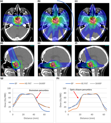
Isodose distributions and dose profiles for patient 1 are shown in Figure 3. The increase in integral dose resulting from the high-energy shoot-through beams is evident. The dose profiles shown in Figure 3g demonstrate that there is minimal difference in the penumbra between the three planning approaches in the plane of the high-energy shoot-through beams. Figure 3h, however, demonstrates a penumbral difference in the plane perpendicular to the high-energy shoot-through beams. This difference is evident at the mid-dose levels, rather than the high-dose levels.
Dose–volume histograms
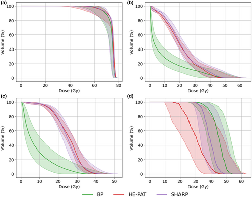
Cumulative dose–volume histograms (DVHs) for the CTV, brainstem and optic chiasm for patient 1 are shown in Figure 4. Near-minimum target coverage is equivalent in all beam delivery approaches; however, increased coverage at 80% of the prescription is evident with SHARP. The shoot-through beams in HE-PAT and SHARP increase the mean dose to the brainstem relative to the BP plan. The smaller spot size of the shoot-through beams in HE-PAT and SHARP reduces the dose to the optic chiasm as this structure lies out of the plane of the proton arc.
Dose–volume metrics
Key dose–volume metrics (DVMs) for the CTV, brainstem and optic chiasm for patient 1 are shown in Figure 5. Points represent DVMs for each uncertainty scenario, and the box plot shows the lower quartile, first quartile, median, third quartile and upper quartile values. A wider spread of points suggests that a plan is less robust for that particular DVM.
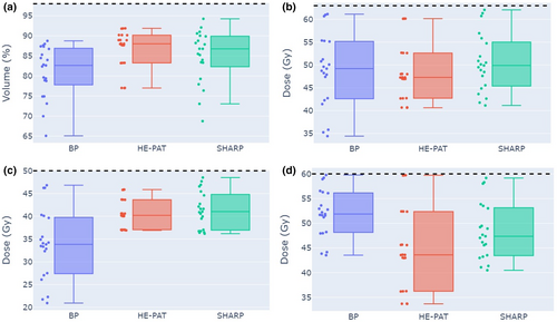
Median target coverage across the uncertainty scenarios was increased in the HE-PAT and SHARP plans relative to the BP plan in patient 1. Median near-max dose to the brainstem core was increased in the HE-PAT and SHARP plans relative to the BP plan in patient 1. Conversely, median near-max dose to the optic chiasm is reduced in the HE-PAT and SHARP plans relative to the BP plan in patient 1. Robust target volume dose–volume metrics for all patients are reported in Table S1. Robust dose–volume metrics for serial OARs for all patients are reported in Table S2. Robust dose–volume metrics for parallel OARs for all patients are reported in Table S3.
LETd–volume histograms
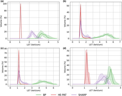
Figure 6 shows the differential LETd–volume histograms for the CTV, brainstem and optic chiasm. In all cases, a reduction in the LETd is observed for the HE-PAT and SHARP plans. As expected, the greatest reduction in LETd is observed in the HE-PAT plan.
Integral dose
Integral doses for each treatment planning technique and each patient are shown in Table S4. Integral dose was calculated as the integral of the differential dose–volume histogram for a given structure. For all patients, an increase in integral dose of at least 155% was observed for the HE-PAT and SHARP plans, with the SHARP plans resulting in lower integral dose compared to the HE-PAT plans.
Discussion
A treatment planning technique that combines the small spot size advantage of shoot-through proton beams with the integral dose advantage of the Bragg peak was successfully demonstrated. In general, it was found that robust target coverage could be marginally improved with the SHARP planning concept relative to conventional IMPT planning. This slight increase in target coverage, however, came at the expense of increased dose to organs at risk located in the plane of the high-energy proton arc. For organs at risk located in the plane perpendicular to the high-energy proton arc, significant dose reductions were observed, validating the theory that the high-energy proton arc contribution can improve the PBT lateral penumbra.
Pencil beams from the high-energy arc were positioned throughout the target volume in the current work, rather than preferentially at the edges of the target volume (from the beam's eye view). This left the responsibility with the optimiser to ensure that the Bragg peak spots were dominating dose at the centre of the target volume rather than the Bragg peak beams. It may be possible to achieve superior results if the high-energy pencil beams are restricted to the target volume boundary from the beam's eye view; however, this level of spot placement control was not possible in the TPS version used in this study. Another approach that may improve upon the results shown in the current work would be to limit the arc angle to avoid organs at risk. In the current work, arc beams were uniformly distributed around an entire half-arc at 20° intervals.
An attractive aspect of the SHARP planning concept is the reduction in LETd to organs at risk abutting the target volume. Indeed, the results of the current study may also be further improved with the use of LETd optimisation.18 In future work, we plan to implement a simple LETd-based RBE dose calculation to compare variable RBE dose distributions between conventional IMPT and SHARP.
There are several practical advantages to HE-PAT delivery. Because the high-energy proton depth dose distribution is approximately constant with depth, only half-arcs are required. This is particularly advantageous for half-gantry proton therapy systems. Also, limiting each beam angle to a single energy removes the time-costly step of needing to change energy layers at each gantry angle, as required in other PAT concepts.
Other single-energy PAT concepts have been proposed by Sanchez-Parcerisa et al.9 and Bertolet and Carabe.10 These studies selected proton beam energies from the beam-angle-specific range of potential energies required to place Bragg peaks within the target volume, rather than using a single high-energy shoot-through energy. The focus of these studies was how single-energy PAT could improve LET distributions relative to conventional IMPT, while also attempting to minimise delivery time. In contrast, the focus of the SHARP concept is to utilise the small spot size of high-energy pencil beams to improve the high-dose lateral penumbra of IMPT, while still considering LET and delivery time. The concepts of Sanchez-Parcerisa et al.9 and Bertolet and Carabe10 would, however, likely result in more favourable integral dose than the SHARP concept.
The inclusion of a non-coplanar vertex field in the conventional IMPT and SHARP plans, but not the HE-PAT plan, is a potential confounding factor in the dose reduction to the optic chiasm observed in patient 1. This is a limitation of the current work, and separating out the effects of spot size and beam configuration on lateral penumbra will be the subject of future work. Additionally, given that the current work was limited to three patient datasets, it is not possible to make conclusive statements about the superiority or otherwise of the proposed planning approach. However, the results are encouraging and we believe warrant further investigation and development of the SHARP planning concept.
Conclusion
A novel PBT treatment planning technique known as SHARP was successfully implemented. Initial results indicate the potential for SHARP to improve the penumbra of PBT treatments for base of skull tumours. Further work involving more customised spot placement and LET optimisation is required to realise the full potential of SHARP.
Acknowledgements
This work was supported by funding from The Hospital Research Foundation under grant no. 2021/45-QA25310. Open access publishing facilitated by The University of Adelaide, as part of the Wiley - The University of Adelaide agreement via the Council of Australian University Librarians.
Conflict of Interest
The author declares no conflict of interest.
Human Research Ethics
The use of patient data for this study is approved under the Central Adelaide Local Health Network Human Research Ethics Committee application 2022/HRE00016.
Open Research
Data Availability Statement
Research data are not shared.


