Identifying rate limitation and a guide to design of fast-charging Li-ion battery
Funding information: Army Research Laboratory, Grant/Award Number: N/A
Abstract
Fast-charging is highly demanded for applications requiring short charging time. However, fast-charging triggers serious problems, leading to decline in charge acceptance and energy efficiency, accelerated capacity degradation, and safety risk. In this work, a three-electrode coin cell with a Li metal reference electrode is designed to individually record the potential of two electrodes, and measure the impedance of each electrode by using a power-optimized graphite-LiNi0.80Co0.15Al0.05O2 electrode couple. It is shown that regardless of the state-of-charge the Li-ion cell's impedance is contributed predominantly by the cathode, and that the cathode's impedance is dominated by the charge-transfer resistance. In consistence with the impedance results, polarization of the Li-ion cell is dominated by the cathode. It is surprised to find that no Li plating occurs on the graphite anode even if the charging rate is increased to 10 C (1 C = 1.30 mA cm−2). The results of this work indicate that low overall impedance with a high cathode-to-anode impedance ratio is the key to enabling safe fast-charging, and that fast-charging Li-ion batteries without Li plating on the graphite anode is possible if the cathode and graphite anode are optimistically engineered.
1 INTRODUCTION
Fast-charging is an important requirement for the application of Li-ion batteries in hybrid electric vehicles (HEVs) and electric vehicles (EVs).1 However, fast-charging triggers a number of problems, leading to reduced energy efficiency, accelerated capacity deterioration, and increased safety risk.2-5 It is commonly believed that low energy efficiency is due to the loss of energy in the form of Joule heat by high current, whereas the others are mainly related to Li plating on the graphite anode by high polarization.2, 6 Li plating on one hand raises safety risk, and on the other hand reacts with electrolyte solvents, leading to low coulombic efficiency, electrolyte depletion, and resultant impedance growth, which are regarded to be the major issue with fast-charging. In previous publications,2, 6-13 nearly all Li plating phenomena were visually observed from the cycled graphite anode, and most conclusions were made by post-mortem analyses on the electrodes harvested from the cycled, aged or failed Li-ion cells. The post-mortem analyses include structural characterizations and electrochemical evaluations. The electrochemical evaluations are performed mostly on a Li half-cell or an electrode/electrode symmetric cell with the harvested electrodes.11, 12 The post-mortem analyses allow to identify structural degradation of the electrode materials, however, they are unable to tell how the electrode materials were deteriorated by fast-charging. Furthermore, both the Li half-cell and symmetric cell cannot exactly clone the electrochemical conditions occurring inside the Li-ion cells. In particular, the plated Li can be re-intercalated into graphite as long as the plated Li is in contact with graphite and the electrode is wetted by the liquid electrolyte to form micro-galvanic cells between the Li and the adjacent graphite particles.6, 8, 14-16 As such, the Li metal observed by the post-mortem analyses only counts for a small portion of the Li plating occurred inside the Li-ion cell.
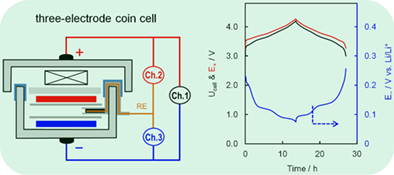
Three-electrode cells with a Li reference electrode enable to simultaneously monitor the cell's voltage and two electrodes’ potential. By defining 0 V vs Li/Li+ as the threshold of Li plating, Li plating on the graphite anode has been operando verified when the Li-ion cells were cycled at high rate or at low temperature.14, 17 In the three-electrode cells previously reported,14, 17, 18 the areal ratio of the Li reference to working electrode is low. In order to acquire accurate potential, a little high reference-to-working electrode areal ratio is needed.19 For this reason, in the present work we designed a three-electrode coin cell, and selected a power-optimized graphite-LiNi0.80Co0.15Al0.05O2 (NCA) electrode couple for demonstration. Using three independent testing channels, we were able to not only compare polarizations of two electrodes but also individually measure impedances of two electrodes at different state-of-charge (SOCs). In this article, we aim to identify the rate limitation to fast-charging and provide a guide for design of the fast-charging Li-ion batteries.
2 EXPERIMENTAL
The graphite anode and NCA cathode, provided by a battery manufacturer, were two-side coated sheets. Prior to use, one side of the coating was carefully removed by first wetting/swelling with N-methyl-2-pyrrolidone solvent and then scraping the coating away from the electrode substrate, followed by punching the electrode sheet into small circular disks with 0.5 in. in diameter (=1.27 cm2) and drying under vacuum at 100°C overnight. The electrolyte used was a solution of 1.0 mol kg−1 LiPF6 dissolved in a 3:7 (wt.) mixed solvent of ethylene carbonate and ethylmethyl carbonate. Using Celgard 2350 membrane as the separator, conventional two-electrode coin cells were assembled for cycling test and three-electrode coin cells were assembled for measuring the electrodes’ potential and impedance. In three-electrode cells, a Li reference electrode was embedded by wrapping a small Li foil with separator and sandwiching it between two separators. For testing consistency, a fixed amount of 40 μL liquid electrolyte was added in all cells, and the cells were formed at 0.1C between 3.0 V and 4.2 V for two cycles before testing.
Cycling test was performed on a Maccor Series 4000 tester, and AC-impedance was measured by a Solartron SI 1287 Electrochemical Interface in combination with a Solartron SI 1260 Impedance/Gain-Phase Analyzer. Rate capability was examined by charging the cell at various rates and discharging at 0.5C between 3.0 V and 4.2 V. Charging time for each rate was determined by the C-rate, for example, 1C, 5C, and 10C correspond to a charging time of 60, 12, and 6 minutes, respectively. AC-impedance was measured at 20°C with a 10 mV perturbation in frequency range from 100 000 Hz to 0.01 Hz by charging the cell to the fully charged state and then discharging at 0.5C to a specific SOC, followed by resting for 20 minutes to reach a stable open-circuit voltage/potential. Impedances of the cathode and anode were measured between the cathode and reference electrode, and between the anode and reference electrode, respectively.
3 RESULTS AND DISCUSSION
3.1 Determination of cathode-to-anode capacity ratio
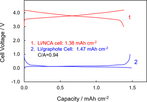
Areal capacity and cathode-to-anode (C/A) capacity ratio were first determined by cycling at 0.1 mA cm−2 between 3.0 V and 4.2 V for a Li/NCA half-cell and between 0.005 V and 1.0 V for a Li/graphite half-cell, respectively. Voltage curves of the second cycle for the above two cells are indicated in Figure 1. It is determined that the NCA cathode and graphite anode have a 1.38 mAh cm−2 and a 1.47 mAh cm−2 areal capacity, respectively, leading to a 0.94 of C/A capacity ratio (corresponding to a 1.06 of negative-to-positive, N/P, capacity ratio as described elsewhere). Based on the above results, a current density of 1.30 mA cm−2 was defined as the 1C rate for further cycling tests.
3.2 Impedance characteristic of Li-ion cells
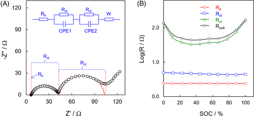
A two-electrode Li-ion cell was examined by AC-impedance spectroscopy. A typical impedance spectrum of Li-ion cells shows two partially overlapped semicircles, followed by a slope straight line as depicted in Figure 2A. According to timescale of the impedance response to AC-signals, the intercept in the high-frequency end is ascribed to bulk resistance (Rb), the diameter of the first semicircle in high-frequency region to surface layer resistance (Rsl), the diameter of the second semicircle in medium frequency region to charge-transfer resistance (Rct), and the slope straight line in the low-frequency end to Warburg impedance (W). In the above electric elements, the Rb measures overall resistance of the cell's hardware and electrolyte/separator, the Rsl corresponds to Ohmic resistance of the surface layer on the electrode particles or the grain boundary contact between the electrode particles, the Rct to Faradic resistance reflecting the electrodes’ reaction kinetics, and the W relates to diffusion process of the Li+ ions on the electrolyte-electrode interface.20, 21 Impedances of a Li-ion cell at various SOCs were measured, and the values of Rb, Rsl, and Rct were fitted using the equivalent circuit shown in Figure 2A and are plotted as a function of the SOC in Figure 2B. It is indicated that the Rb and Rsl are almost SOC-independent, whereas the Rct changes vastly with the SOC. It is important to observe that the Li-ion cell's resistance is contributed predominantly by the Rct, and that the Rct gets much higher approaching the charging and discharging ends (ie, in the regions near 100% and 0% SOCs) as compared with those in the middle SOC region. We previously found that the Rsl in the lithium half-cell changes greatly with the SOC, and those in the Li/cathode and Li/graphite half-cells are changed inversely with respect to the SOC.20 Therefore, the apparent Rsl-SOC independence observed in Figure 2B can be attributed to a combined result of the Rsl in the NCA cathode and graphite anode. Since the Rct reflects the electrode's reaction kinetics, there is an excellent corresponding relationship between the Rct and the cell's differential capacity. That is, the change of Rct with the SOC well follows the pattern of differential capacity, and a low Rct corresponds to a high differential capacity.20, 21 This explains why the Rct in Figure 2B gets much higher near the charging and discharging ends, where the cell's differential capacity approaches zero.
Since the Rsl and Rct of the cathode and anode change with the SOC, impedances of the Li-ion cell, NCA cathode, and graphite anode are respectively measured in three representative SOCs of 0%, 50%, and 100%, and the results are compared in Figure 3. Regardless of the SOC, the following three phenomena are observed: (a) the Li-ion cell's impedance equals to the sum of the cathode and anode's impedances, (b) the Li-ion cell's impedance is contributed predominantly by the NCA cathode, and (c) the NCA cathode's impedance is dominated by the Rct. At 100% SOC (Figure 3E,F), for example, the total resistance (ie, Rb + Rsl + Rct) of the Li-ion cell, NCA cathode, and graphite anode are calculated to be 68, 62, and 5 Ω, respectively, in which the NCA cathode contributes to 91% of the cell's overall impedance. In particular, in the NCA cathode the Rct is fitted to be 49.5 Ω, occupying ~80% of the cathode's impedance. The above results are attributed to the much sluggish Li+ ion mobility in the NCA host compared with that in the graphite. It was reported that Li+ ion diffusivity in the graphene planar direction of graphite reaches as high as 10−7-10−6 cm2 s−1,22 while that in the NCA is only ~10−10 cm2 s−1.23, 24 Therefore, it may be concluded that the NCA cathode is the rate limitation to fast-charging of the graphite/NCA Li-ion cell.

3.3 Fast-charging performance
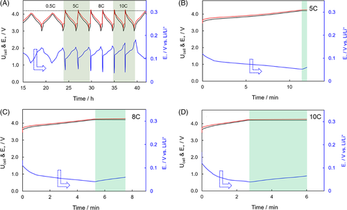
After two forming cycles at 0.1 C, the Li-ion cell was tested by charging at various rates and discharging at 0.5 C between 3.0 V and 4.2 V. The effects of charging rate on capacity (or called “charge acceptance”) and polarization are depicted in Figure 4. It is estimated from Figure 4A that the Li-ion cell was able to retain a 1.05 mAh cm−2 capacity (equating to 84% of the capacity, 1.25 mAh cm−2, at 0.5 C) and a 99.7% coulombic efficiency even when the charging rate was increased to 10 C. More importantly, the capacity well recovered after the charging rate was returned from 10 C to 0.5 C. Figure 4B compares polarization and charge acceptance of the cell at various charging rates. It is observed that with an increase in the charging rate, the cell's polarization is dramatically increased, which consequently leads to a decrease in both the charge acceptance and the constant-current to constant-voltage (CC/CV) charging capacity ratio.

 (1)
(1)
 (2)
(2) (3)
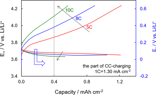
(3)Figure 6 compares polarizations of the cathode and anode at various CC-charging rates with the E+ and E− being plotted on the same scale. It is observed that the polarization of the NCA cathode is much larger than that of the graphite anode, which is in good agreement with the impedance results as shown in Figure 3. In the state of 0.40 mAh/cm2 (corresponding to a 30.8% SOC, as marked by the dot line in Figure 6), for example, the E+ increases from 3.865 V to 4.115 V, leading to a 0.250 V increase, whereas the E− declines from 0.078 V to 0.035 V, leading to only a 0.043 V decrease when the charging rate was increased from 5 C to 10 C. Much higher polarization of the cathode than the anode enables safe fast-charging of the Li-ion batteries without Li plating on the graphite anode.
3.4 A guide to design of fast-charging Li-ion battery
While Li plating on the graphite anode during fast-charging was frequently reported and the graphite anode was considered to be the rate-limiting electrode,2, 6, 11, 12, 14 the exceptionally good fast-charging performance obtained in the present work can be attributed to the much larger impedance of the NCA cathode than the graphite anode. Other factors affecting Li plating are electrolyte (with separator) and temperature. When ionic conductivity of the electrolyte/separator is low, especially at low temperature, the large η− can drive the E− to lower than 0 V vs Li/Li+ and hence trigger Li plating. In view of increasing the electrolyte’ ionic conductivity and electrode's reaction kinetics, the Joule heat generated by high current in fast-charging is favorable for avoiding Li plating. This is true, especially for large-size Li-ion batteries in which self-heating effect is significant. Theoretically, the Li metal observed in the post-mortem analysis must be the dead Li or that in the area where the electrode was dried so that no micro-galvanic cells could be formed between the Li and the adjacent graphite. Nearly all Li plating phenomena previously reported were observed from either severely aged or failed Li-ion cells,2, 6-8, 10-13 in which the impedance of the graphite anode was comparable or even much higher than that of the cathode. As such, the E− falls to lower than 0 V vs Li/Li+, triggering Li plating, when the Li-ion cell is charged rapidly. However, in such a case, the cathode must be under-charged as predicted by Equation (1). That is, the E+ is lower than the Ucell so that capacity of the cathode cannot be fully accessed if the charging process is still ended by the normal upper cutoff voltage. In addition, dissolution of transition metal (TM) ions is a common problem of the Li-ion cathode materials, and the TM dissolution aggravates with an increase in the charging cutoff voltage.26-29 In the aged or failed Li-ion cells, more or less TM ions were dissolved into the electrolyte and migrated to the graphite anode where the TM ions were either electrochemically reduced to metal or incorporated to the solid electrolyte interphase (SEI), resulting in a dramatic increase in the SEI impedance.30, 31 When this happens, the order of the impedances of the cathode and anode would be inverted, and the E− could easily decline to lower than 0 V vs Li/Li+. It was reported18 that for a graphite/LiMn2O4 Li-ion cell, the impedance of the graphite anode was much smaller than that of the cathode in the initial stage, however, it became much larger than that of the cathode after only 25 cycles at 55°C as a result of the Mn2+ dissolution and resultant incorporation to the graphite's SEI. As such, the graphite anode turned to be the rate-limiting electrode for fast-charging.
Based on the above analyses, fast-charging without Li plating on the graphite anode is possible only for health Li-ion cells, in which the cathode has much higher impedance than the graphite anode. Li plating on the graphite anode would occur only when the polarizations of the cathode and anode are comparable or when the polarization of anode is larger than that of the cathode. Unfortunately, this is often the case when the Li-ion cells get aged or approach failure. Li plating not only raises safety risk by dendritic deposition, but also depletes Li+ ions from the cathode by low coulombic efficiency. The latter lifts the cathode's working potential region so that the cathode can be overcharged even if the Li-ion cell is charged within the normal voltage range.12, 32 On the other hand, the TM dissolution dramatically increases the graphite anode's impedance, and it aggravates with an increase in the E+ or temperature.26-29 Therefore, overcharging must be avoided for safe fast-charging and long cycle life. The results of this work indicate that low overall impedance with a high C/A impedance ratio is the key to enabling safe fast-charging and that overcharging is the origin for performance degradation of the cathode and Li plating on the graphite anode.
4 CONCLUSIONS
In summary, a three-electrode Li-ion coin cell with a Li reference electrode enables to simultaneously monitor the cell's voltage and two electrodes’ potential, and individually measure the cell's and electrodes’ impedance. It is shown that charging at 10C without Li plating on the graphite anode is possible for health Li-ion batteries with a power-optimized graphite-NCA electrode couple. The excellent fast-charging capability obtained in the present work is attributed to the much higher impedance of the cathode than the graphite anode. The results of this work indicate that low overall impedance with a high C/A impedance ratio is the key to enabling fast-charging without Li plating on the graphite anode. This could be an important guide for designing of the fast-charging Li-ion batteries.
ACKNOWLEDGMENTS
The author acknowledges support of U.S. Army Research Laboratory and Dr. C. Lundgren for her critical reading of the manuscript and valuable comments.
CONFLICT OF INTEREST
The author declares no conflict of interest.


