CH4/air combustion in a microscale recirculating heat exchanger: Sizing design using the heat transfer approach
Abstract
Microcombustors are microscale combustion devices that can be used to power microelectromechanical systems. Many combustor configurations are reported in the literature and, among them, combustion in a microscale recirculating heat exchanger is a feasible option. In this work, a simple, double-channel, recirculating heat exchanger is considered. The novelty of the present work lies in the heat transfer analysis approach to design a microcombustor. A combustor is designed using thermal resistance networks for a premixed fuel containing a methane–air mixture in stoichiometric ratio. The length of the combustor is designed based on the position of the combustion flame. Computational fluid dynamics is utilized to validate the theoretical results. The analysis is carried out for adiabatic and nonadiabatic conditions. The combustor lengths for adiabatic and nonadiabatic (ceramic) combustors vary from 39 to 242 mm and 49 to 276 mm, respectively, for variations in the mass flow rate of the premixed gases from 6 to 10 mg/s. A minimum limiting flow rate of 6 mg/s was identified. The average error in the maximum combustion gas temperatures between the theoretical and CFD results obtained in this work is 4.2%. The theoretical approach presented can be suitably applied to more complex geometries involving multichannels and variations in geometrical properties.
1 INTRODUCTION
Microelectromechanical systems (MEMS) are extensively used in day-to-day life for various applications, including microsatellites, microsensors, microaerial vehicles, and so on, and they are usually powered by batteries.1 Low power density and frequent charging requirements of batteries reduce their effectiveness in these applications.2 Microcombustors are microscale combustion devices, and they can be effectively used in MEMS. For instance, the use of hydrogen and hydrocarbon fuels in microcombustors provides higher energy density power sources.3 Apart from their advantages, microcombustors have high surface to volume ratios, which increases the heat transfer to the combustor walls and causes flame quenching.4 Flame stability and complete combustion of the premixed air fuel mixture is important to achieve higher efficiency.5
Microcombustion technology is generally thought to have been first proposed in 1997 by Epstein and Senturia.6 Since then, extensive studies have been carried out for the development and application of microscale systems to produce power through hydrogen and hydrocarbon combustion. The rate of microscale combustion depends on several physical and chemical factors such as gaseous and surface reactions, transport mechanism of molecules, heat transfer by convection and radiation and mass diffusion.7 The combustion process for micro-power generation involves many lengths and time scales. The stability of the flame depends on the heat loss and quenching thickness, and excessive heat loss from the combustor wall results in flame extinguishing.8 Flame stability and achieving higher combustion efficiency are twin challenges and these are influenced by heat loss ratio, residence time, and the coupling between flame and wall.7 A lower combustor temperature results in reduced heat loss due to lower flame speed.9 Good fuel and air mixing performance and flame stability, and higher and more uniform outer wall temperatures, are obtained when microcombustion occurs with a catalyst.1 The combustion quality, heat of reaction, and total heat flux at the gas–solid interface can be enhanced by catalytic combustor. Yan et al.10 numerically investigated the catalytic action of methane-fueled microcombustion for an opposed counter-flow microcombustor and compared it with the conventional type. They reported improved combustion efficiency and better thermal cycling for the newly developed microcombustor compared to the conventional. When the inlet velocity is maintained at 1.1 m/s, the opposed counter-flow microcombustor increases the combustion efficiency and blow-off limit by 18.3% and 165%, respectively, compared to the conventional one. The counter-flow combustors facilitate measuring the velocity of flame propagation and stretched premixed flame extinction.11 These types of combustors are reliable and provide effective flame stability to extend the flow residence time.12 Slotted or controllable slotted bluff body catalytic microcombustors have been shown to exhibit better combustion performance with stable flame when the gap width is maintained at 0.6 mm.13 Catalysts with higher surface-to-volume ratio promote more sites for the adsorption of fuel and oxidizer.14 Hence, catalytic combustion can improve flame stability and conversion efficiency in microcombustors. Li et al. conducted a numerical analysis to study the geometry and flame temperature on a methane air-premixed microcombustion.15 A limiting flow velocity was obtained for which the flame temperature was a maximum. It was seen that the microcombustor with 1 mm diameter had negligible effects of slip-wall boundary. Yilmaz et al. conducted a numerical study of a geometrically modified microcombustor using ANSYS Fluent.16 Turbulence model (k–ε) was used with Eddy dissipation. A backward-facing step arrangement benefitted the temperature distribution and increased outer wall mean temperature. To overcome the heat losses in microcombustors, Yilmaz investigated the insertion of a bluff body in the combustion zone augmented by oxygen-enriched air for combustion.17 In addition, a perforated plate was also inserted and found to have the highest thermal performance in terms of thermal kinetics and heat transfer characteristics. The author used the Eddy dissipation model for combustion and k–ε model for the fluid flow. Zuo et al. also conducted numerical investigations to improve the thermal performance of a double-channel microcombustor.18 The investigation was carried out for three different wall materials, quartz, carbon silicon, and steel. Compared to a straight single-channel combustor, the improved double-channel combustor had better thermal performance. It was revealed that a limiting mass flow rate of the hydrogen–air mixture exists beyond which the heat losses are significant, and the equivalent ratio cannot be less than 0.5. Enagi et al. used ANSYS-Fluent for the numerical investigation of a microscale gas turbine.19 k–ε model was used along with both finite-rate and Eddy dissipation mode. An optimum configuration was arrived at by varying different design parameters and combustion models. The geometry of the microcombustor plays an important role in maintaining combustion stability and heat loss. Several studies have proposed different microcombustor designs and investigated combustion characteristics.20-24 Research team at Jiangsu University carried out an experimental and kinetic analysis on the flame stabilization of cofired ammonia/hydrogen–air mixtures.25 Flame propagation is facilitated with the increase in the blend ratio which also increases the blow-off limit. The team also conducted optimization studies using a genetic algorithm to obtain the optimal characteristics in terms of radiation efficiency, standard deviation and volume power density for a methane-fired slit type microcombustor.26 Different regimes of thermal conductivities are identified. An exergy and entropy analysis is also carried out by the team in a methane/dimethyl ether/air premixed combustion in a microchannel.27 From the list of chemical reactions, a single step is identified that contributes to maximum entropy generation. Higher exergy efficiency can be achieved at high velocities and blending ratio. He et al.28 numerically studied the influence of pin fin arrays on the nature of combustion and thermal augmentation of premixed hydrogen/air in microcombustor. Staggered pin fin arrays result in the highest average temperature and heat flux of external wall, while in-line pin fin arrays exhibit the most uniform temperature distribution on the external wall. A rectangular-ribbed microcombustor has higher exergy efficiency compared to a plain microcombustor for various hydrogen mass flow rates. A system with a mass flow rate of 7.9 × 10⁻⁷ kg/s hydrogen exhibited an increase in the exergy efficiency by 130.3%.29 A double layer multichannel microcombustor with counter-flow results in the highest total energy conversion efficiency of 13.2% when the hydrogen mass flow rate is maintained at 8.1 × 10⁻⁷ kg/s.30
Designing of a combustor with respect to the control of flame propagation is a challenging task. Hence the limiting values of velocities such as the blow-off limit and the flashback limit become extremely important. These important limiting velocities depend on several factors such as fuel and oxidizer composition, equivalence ratio, initial mixture temperature, combustion chamber pressure, combustor geometry, and burner wall types. The literature on design and sizing calculations of a microcombustor is scanty. Hence, in this paper, a simple heat transfer analysis is applied to a counter-flow recirculating microscale combustor to arrive at a minimum sizing requirement for flame sustainability inside the combustor.
2 MATERIALS AND METHODS
2.1 Heat transfer modeling
A counter-flow recirculating burner is selected in this work, as shown in Figure 1.
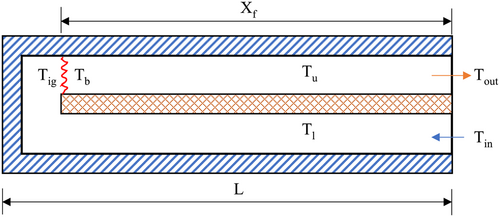
The lower channel contains an unburnt premixed gas mixture of CH4/air that enters the combustor at point A at temperature and traverses along the length, L. The upper channel contains a mixture of burnt gases that moves in a counter-flow direction and exits the combustor at B with a temperature . The burnt gases in the upper channel supply heat to the unburnt gases in the lower channel via a diathermic wall made of copper. The enthalpy of unburnt premixed mixture is thus increased along the length of the combustor and the temperature reaches a value of , which is the autoignition temperature, or the temperature of the premixed gas mixture just before combustion. is the temperature of the burnt gases just after combustion. The temperature in the upper channel typically exhibits a decreasing trend due to heat transfer to the diathermal wall and heat loss to the surroundings. For an adiabatic condition, heat loss from the combustor to the surroundings is neglected. However, a more practical scenario would be to consider heat transfer through the external walls wherein a part of heat from both the lower and upper channels is assumed to be lost to the surroundings. The dimensions of the channel width and wall thickness are fixed at 2.5 and 1 mm, respectively.
The sizing design in this study is carried out with regard to only the length of the combustor. Heat transfer analysis is applied in the direction normal to the direction of the flow of gases. Figure 2 shows the thermal resistance network of the combustor at any point along the length of the combustor. The purpose of recirculating burner is that a part of the heat from the products can be transferred to the reactants to preheat it and increase the enthalpy of the reactants. When there are considerable losses in the channels to the surroundings, excess heat may not be available to increase the enthalpy of the reactants. The research reported here is carried out for three conditions: (i) adiabatic, (ii) nonadiabatic with external wall made of aluminum, and (iii) nonadiabatic with an external wall made of ceramic (zirconium phosphate).

The heat transfer analysis is carried out on the model by first determining the thermal resistance network as shown in Figure 2. Here, is the ambient temperature, and correspond to temperature in the lower and upper channels, respectively, is the temperature of the internal diathermal wall, and are the temperatures of the external wall near the upper and lower channels, respectively. , , and are the convective thermal resistances for the ambient (air), CH4/air mixture in the lower channel, and combustion products in the upper channel, respectively. , , and are the thermal resistances due to conduction heat transfer in the external wall at the lower channel, diathermal wall, and external wall at the upper channel, respectively. There are ten temperature variables to be solved for, including the eight variables seen in Figure 2 ) along with the temperatures and .
The parameters that are known before conducting the heat transfer analysis are as follows: inlet temperature of the reactant mixture, ; pressure at which the gases enter and leave the combustor, which are assumed atmospheric; mass flow rate of the gas, ambient temperature and combustor channel cross-sectional area, .
Here, is the heat of reaction. The enthalpies of the reactants and products are determined from standard thermodynamic property tables.31 The temperature of the burnt gas temperature just after combustion is thus calculated.
The equations are solved for the first step considering and . For the next step, and are replaced by and , respectively. The iterative procedure is stopped when the temperature in the upper channel reaches a temperature of and the temperature in the lower channel reaches . The flame will be sustainable if the temperature profile in the upper channel exactly meets the temperature profile in the lower channel. The corresponding step size indicates the minimum size (length) of the combustor required for flame sustainability.
2.2 Numerical model
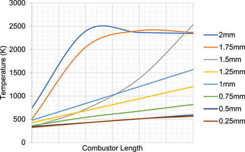
The adiabatic and nonadiabatic models, as calculated from the theoretical approach, are analyzed using computational fluid dynamics to observe the temperature and velocity contours. For the CFD analysis, a two-dimensional model is developed and meshed using Gambit 2.5 and analyzed using ANSYS Fluent 14.5. A mesh size of 0.5 and quad elements were chosen with a total of five boundary layers starting with 0.1 mm and a uniform growth factor of 1.05. A mesh convergence study was also carried and the convergence of temperature profile was checked against various mesh sizes from 0.25 to 2 mm as shown in Figure 3. This check showed that no significant deviation in the temperature profiles was found when the mesh size was reduced below 0.5 mm. Hence the results extracted and displayed for all the models utilize a mesh size of 0.5 mm. The inlet boundary condition is specified as mass flow inlet and the outlet as pressure outlet. The outer wall is not modeled for the adiabatic combustor whereas, for the analysis of the nonadiabatic combustor, an outer wall enclosing the system is modeled and meshed. The model chosen for the analysis is a standard k–ε model with standard wall function. The combustion model chosen is species transport with volumetric Eddy dissipation. The fluid is selected as a methane–air mixture. The species concentration is specified both for the inlet and the outlet side. In the case of nonadiabatic combustion, a discrete ordinate model is invoked for the radiation heat transfer. Due to the combustion present in the channels, the heat transfer to the walls be present via radiation mode. Another prominent factor is the high surface to volume ratio wherein radiation heat transfer may be significant. The discrete ordinate model accommodates the spectral and space variations in the radiative properties. An isotropic radiation pattern is assumed considering equal absorption of the emitted radiation in all directions. The heat transfer coefficient at the outer walls of 5 W/m2K and an ambient temperature of 300 K are specified for facilitating heat transfer from the inside product gases to the surroundings. Table 1 shows the results (burnt gas temperature) obtained from both the theoretical and CFD analyses. Reynolds number is calculated using the REFPROP33 database for varying temperatures and flow rates. The Reynolds number vary from 1895 at a flow rate of 6 mg/s to 3025 at a flow rate of 9 mg/s. Increasing the flow rate increases the Reynolds as it increases the inertial effects. An increase in the flow rate also increases the temperature, which slightly reduces the Reynolds number due to the effect of viscous forces.
| Gas flow rate (mg/s) | 6 | 7 | 8 | 9 | 10 |
|---|---|---|---|---|---|
| Adiabatic combustor | |||||
| Theoretical analysis | 1652 | 1729 | 1802 | 1874 | 1946 |
| CFD | 1703 | 1777 | 1884 | 1962 | 2051 |
| Nonadiabatic combustor (Ceramic wall) | |||||
| Theoretical analysis | 1644 | 1725 | 1801 | 1872 | 1944 |
| CFD | 1683 | 1772 | 1875 | 1931 | 1999 |
3 RESULTS AND DISCUSSION
3.1 Adiabatic combustor
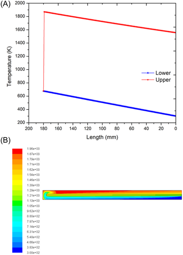
Figure 4A shows a plot along the length of the adiabatic combustor against temperature for a gas flow rate of 9 mg/s. The blue line indicates temperature in the lower channel of the combustor and the red one indicates the upper channel. It can be seen that the mixture of gases enters the combustor at atmospheric temperature 27°C and the temperature rises gradually in the lower channel. The burnt gas temperature reaches a value of 1601°C in the upper channel. The presence of high-temperature burnt gases in the upper channel transfers a part of its heat to the incoming fresh unburnt gas mixture. The incoming gases pick up heat from the burnt gases, and their temperature is elevated to the ignition temperature. The minimum distance the incoming gases must travel to become elevated to the ignition temperature is the required length for the given configuration. Hence for any given mass flow rate, inlet temperature, and cross-sectional details, the optimum length of the combustor is effectively determined in this study as that which is sufficient enough to sustain combustion. Figure 4B shows the temperature contour plot of the numerical analysis using CFD for the same problem. The temperature rises from 27°C (300 K) at the inlet to a maximum of 1689°C (1962 K) towards the end of the combustor. The difference in the burnt gas temperature obtained from the heat transfer analysis and CFD analyses is 88°C The same analysis was repeated for various flow rates of the gases. The temperature profile, combustor length, ignition and burnt gas temperatures, and outlet temperatures were calculated for each case.
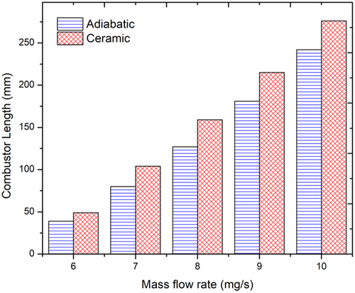
The combustor size is plotted against mass flow rate in Figure 5. As the mass flow rate increases, the combustor length also increases. The combustor length increases from 39 mm for a flow rate of 6 mg/s to 242 mm for 10 mg/s. The increase in the combustor length provides greater time and surface area for transferring heat from the upper channel to the lower channel. It is also seen that flame cannot be sustained for a mass flow rate below 6 mg/s. This is because, at lower flow rates, there is not enough velocity to drive the gases through the inlet and outlet channels. The outlet temperature remains the same for all mass flow rates considered. This means that the solution procedure typically fixes the temperature at the outlet and allows variation in the length of the combustor to obtain sustainable combustion. Hence the sizing calculation is suitably made depending on the length of the combustor. As the flow rate increases, there is more fuel being burnt and at higher velocities. Also, it is observed that, as the flow rates are increased, the ignition temperature also increases.
For a given fuel–air mixture, pressure, and geometry of the combustor, the increase in the mass flow rate of the mixture increases the value of the term in Equation (9). Hence, either or should increase. On the other hand, increasing the ignition temperature increases the overall value of the term , leading to an increase in the mass flow rate. Hence the converse meaning also holds wherein increasing the mass flow rate of the gas results in an increase in the ignition temperature of the gases inside the combustor. In the theoretical analysis, therefore, the value of combustor lengths also increases to allow more time and area for heat transfer to the inlet which can increase the unburnt gas temperature and maintain the required outlet temperature.
As remains constant for any given fuel–air mixture, the mass flow rate and enthalpy difference between unburnt and burnt gas are inversely proportional. Hence at higher mass flow rates, the temperature rise from to decreases.
3.2 Nonadiabatic aluminum combustor
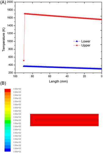
For the problem of the nonadiabatic case, there is a wall at the outside of the inner and outer chambers that can dissipate heat to the surroundings. Figure 6A shows the temperature distribution in the lower and upper channels with aluminum as the external wall material. From the figure, it can be observed that the inlet gas mixture obtains heat from the heat of the burnt gases and the temperature rises. On the outlet side, the temperature drops from the outlet temperature determined to the burnt gas temperature, . At the opposite end of the combustor, we observe a temperature dip from burnt to unburnt gas temperature, . At the end of the inlet channel, the reactant mixture should attain the unburnt gas temperature required for self-ignition and thus burn and move ahead in the outlet channel. But the temperature difference between the reactant temperature at the end of the inlet channel and the unburnt gas temperature is high (>140°C) and hence the flame is not established. Figure 6B shows the CFD results for the same case. It is clearly observed that no change in temperature is obtained. This is because, at steady state, ignition does not occur and hence the premixed CH4/air mixture exits the combustor at 27°C (300 K) without combustion. The reason for this kind of case is that part of the heat gained from the excess enthalpy of the products is lost to the surroundings through the outer wall. To sustain the flame for the aluminum combustor, an additional heat flux needs to be supplied at the opposite end to make up for the deficiency in heat.
3.3 Nonadiabatic ceramic combustor
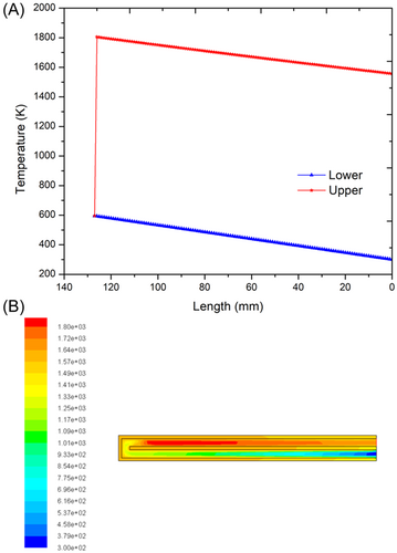
To reduce the heat loss to the surroundings in the nonadiabatic combustor case, an external wall material with low thermal conductivity (zirconium phosphate, k = 0.8 W/mK) is chosen and the heat transfer analysis is carried out. A sustainable flame can be established when the external wall material is specified as ceramic. Figure 7A shows the temperature profile of the ceramic combustor obtained from the heat transfer analysis for a flow rate of 8 mg/s. The premixed gas temperature enters the combustor at 27°C (300 K) and receives heat from the upper channel through the diathermal wall. The ignition occurs at the end of the channel and reaches a burnt gas temperature of 1528°C (1801 K). The results are validated using CFD as shown in Figure 7B. From the CFD analysis, it is seen that the maximum burnt gas temperature obtained is 1602°C (1875 K). The difference between the results of heat transfer analysis and CFD is 74°C. This model avoids any additional heating source, which was required in the previous case having aluminum as the outer wall material. A comparison of combustor sizing (length) considering various flow rates for the ceramic combustors is shown in Figure 4. The ceramic combustor size increases from 49 mm for a flow rate of 6 mg/s to 276 mm at a flow rate of 10 mg/s. Compared to the adiabatic combustor, the increase (%) in the size of the ceramic combustor is 25.6%, 30%, 25.2%, 18.8%, and 14.0%, respectively, for flow rates of 6, 7, 8, 9, and 10 mg/s. The increase in the combustor size is to make up for the heat losses that occur through the external wall of the ceramic combustor.
The nonadiabatic combustor with ceramic wall material has a combustor length greater than that of an adiabatic combustor at all flow rates. Compared to the aluminum combustor, the thermal conductivity of ceramic (zirconium phosphate, 0.8 W/mK) is 200 times less, which allows the heat of the products to be retained within the system itself. Since the heat loss from the inlet and outlet side is much lower, the incoming gases easily gain the heat from the product mixture and can be elevated to the ignition temperature. As heat loss is still unavoidable, the incoming reactant mixture requires additional exposure from the heated product mixture to attain the required . This happens via an additional combustor length and is more than the adiabatic combustor length.
4 CONCLUSIONS
-
A sustainable combustion process was obtained only in adiabatic and ceramic combustors. The aluminum-walled combustor could not sustain a steady state combustion due to its higher thermal conductivity allowing all the heat loss to the surroundings. The theoretical heat transfer analysis showed that the outlet temperature was fixed and allowed variation in the combustor length for adequate heat transfer and flame sustainability.
-
The combustor lengths of adiabatic and ceramic combustors varied from 39 to 242 mm and 49 to 276 mm, respectively, for a variation in the mass flow rate of the premixed gases from 6 to 10 mg/s. A limiting minimum flow rate of 6 mg/s was obtained below which combustion could not be sustained.
-
The CFD analysis validated the theoretical approach in this work. Both the theoretical heat transfer analysis and the CFD analysis showed that combustion occurred at the extreme end of the combustor.
The theoretical heat transfer analysis presented in this work provides a simple mechanism for designing and sizing a microcombustor. This method is suitable to be applied for other complex geometries like multichanneled heat exchangers or swiss-roll combustors. Further parametric studies in conjunction with design of experiments and optimization studies can be carried out by varying the thermal conductivity of external wall, channel opening, and wall width to ascertain the combustion behavior of combustion sustainability.
NOMENCLATURE
-
-
- heat of reaction
-
- A
-
- cross-sectional area of the channel
-
- CH4
-
- methane
-
-
- hydraulic diameter
-
-
- enthalpy
-
-
- heat transfer coefficient
-
-
- thermal conductivity
-
- L
-
- combustor length
-
-
- mass flow rate
-
- MEMS
-
- microelectromechanical systems
-
-
- Nusselt number
-
-
- pressure
-
-
- characteristic gas constant
-
-
- thermal resistance
-
-
- flame speed
-
-
- temperature
-
-
- velocity
-
-
- density
AUTHOR CONTRIBUTIONS
Sooraj Mohan: Conceptualization, data curation, investigation, formal analysis, software, writing-original draft. P. Dinesha: Conceptualization, supervision, visualization, writing, reviewing and editing. Marc A. Rosen: Conceptualization, writing, reviewing and editing.
CONFLICT OF INTEREST STATEMENT
The authors declare no conflict of interest.
Open Research
DATA AVAILABILITY STATEMENT
The data that support the findings of this study are available from the corresponding author upon reasonable request.


