Optimal arch forms under in-plane seismic loading in different gravitational environments
Abstract
This paper is motivated by the renewed interest in space exploration and the need to provide structurally sound and resource-efficient shielding solutions for valuable assets and future habitable modules. We present, implement and test a methodology for the preliminary design and assessment of optimal arch forms subjected to self-weight as well as seismically induced loads. The numerical framework, built around a limit thrust-line analysis, previously published by the authors, is summarized first. This is followed by a detailed account of the form-finding algorithm for arches of variable thickness. Special attention is placed on the physical feasibility of our assumptions and the justification of the engineering inputs adopted. The newly form-found arches achieve material efficiencies between 10% and 50% in comparison with their constant minimum-thickness circular or elliptical counterparts, depending on the relative intensity of the seismic action. The influence of the initial input geometry and the stabilising presence of additional shielding material against extreme radiation are also evaluated with emphasis on the effects of low-gravity conditions. Finally, a case study is presented and Discrete Element Models of constant and varying thickness arches (VTAs) are assessed under a set of representative ground-motions on a lunar setting. The significant over-conservatism of constant thickness arches (CTAs) is made manifest and potential improvements of the optimally found arch shape are highlighted. Although developed with extraterrestrial applications in mind, the results and methods we present herein are also applicable to terrestrial conditions when material efficiency is of utmost concern.
1 INTRODUCTION
Arches are widely used as structural elements in the construction of coverings for open spaces where they can be subjected to lateral action from seismic events. Although they have been the subject of intensive analysis since the XVII Century, there is a dearth of research on their shape optimization when subjected to horizontal seismic loads; and, to the authors' knowledge, only a handful of studies have dealt with this. By contrast, a large amount of research has been carried out on the analysis of masonry arches subjected to vertical loads. In this context, the optimal shape of a masonry arch is often associated with the catenary.1, 2 This is despite the fact3 that there is no minimum thickness associated with a catenary arch under its own weight. Moreover, Milankowitch4 and Makris and Alexakis5 demonstrated that, apart from 1D arches, admissible thrust-lines cannot be of catenary shape, hence an arch of finite thickness that resembles a catenary can not be automatically assumed to be optimal. Past studies have mostly examined the stability of arches of classical form under static loads focussing on arches of classical form like semicircular,1, 4-7 parabolic,8, 9 elliptical10 and catenary arches.3, 11
The issue of finding the optimal shape of arches subjected to concurrent vertical and seismic loads is particularly important for the provision of extraterrestrial outposts where material efficiency is of paramount importance, especially as lunar ground motions can pose a threat to the settlements.12 With the increasing level of interest in space exploration from both public bodies and private firms,13 the demand and need for the design of resilient lunar and martian habitats have become apparent. In this context, 3D-printed arch structures that make use of an in situ resource utilisation (ISRU) framework are potentially of great value as they require minimal transportation of material from Earth.14 The use of 3D-printing will also allow for the construction of structures ‘of considerable dimensions, with virtually any shape’.15 Nevertheless, extraterrestrial structures will be subject to extreme design conditions due to the harsh environment.16-18 As summarised by Kalapodis et al.,13 there are four potential sources of lunar ground motions: deep moonquakes, shallow moonquakes, thermal moonquakes and meteorite impacts; and similar conditions are expected on Mars. Thermal moonquakes are very small magnitude events caused by the extreme temperature variations on the Moon and are unlikely to be a key design consideration for lunar structures. However, due to the far thinner atmosphere on the Moon or Mars compared to Earth, seismic motion due to meteoroid impacts can pose a significant hazard to extraterrestrial structures.19
The optimization of arches subjected to both their own weight and lateral seismic action has only been recently explored. The first attempt to include lateral forces into a form-finding method based on Thrust Network Analysis (TNA) was performed by Marmo and Rosati.20 Although the TNA method in its original form21 can be used to produce compression-only shells under vertical loads, Marmo and Rosati's reformulation20 involved a dissociation of the force diagram from its reciprocal form counterpart, thus severing its applicability for optimization studies. On the other hand, Michiels and Adriaenssens22 used graphic statics to generate arches subjected to gravity and seismic loads based on the geometric manipulation of funicular polygons obtained under statical lateral forces. However, the use of funicular polygons does not guarantee the optimality of the arch shape and its geometrical manipulation poses questions as to the physical interpretation of the procedure. More recently, Kimura et al.23 proposed a method for the shape optimization of tapered arches subjected to horizontal loads by discretizing them into a series of beam elements with piecewise constant section and minimizing their total strain energy. This study focused on limiting the effect of bending on the arch (finite stiffness), in order to generate no-tension arches by operating on the coordinate control points and updating the sections of the ‘numerical’ beams. All these studies have focused on terrestrial applications and the effects of low-gravity conditions were not explored. The first study to consider the effects of low gravity on the stability of arches was conducted by Kampas et al.24 They employed a variational formulation to conduct thrust-line analyses of parabolic arches and concluded on the importance of carrying out dedicated optimization studies for arches of varying thickness under low gravity.
This paper focuses on the optimization of arch shapes for protective extraterrestrial structures subjected to a combination of vertical and lateral seismic loads. We propose and implement a computational methodology based on equivalent static loads and limit thrust-line analysis for the generation of optimal arch shapes under varying gravitational conditions. Therefore, we assume structures with: (i) infinite stiffness, (ii) infinite compressive strength, (iii) zero tensile strength, (iv) no shear consideration and (v) no sliding (as appropriate for monolithic arches without physical voissoirs). Moreover, the effect of stereotomy on the structural shape is out of the scope of this paper. Unlike previous studies where a number of arbitrary design decisions had to be made, which can arguably compromise the physical meaning of the thrust-line methodology, in this paper, we pay special attention to the justification of the engineering inputs adopted and the rationalization of our thrust-line manipulation. Initially, the paper introduces the numerical thrust-line analysis framework adopted. This is followed by the presentation of a rigorous form-finding algorithm and its application to the exploration of optimal arches of varying thickness. The structural benefits of additional loose regolith shielding are also explored. Importantly, the tools and methods developed are intended for the initial design stages where an exploration of materially efficient forms is crucial before embarking into more detailed structural analyses. Also, although developed with extraterrestrial applications in mind, the results and methods we present herein are also applicable to normal terrestrial conditions whenever the design may be governed by material saving considerations.
2 NUMERICAL LIMIT THRUST-LINE ANALYSIS FRAMEWORK
The numerical procedure for thrust-line analysis presented previously in McLean et al.25 is used herein. In it, McLean et al. discretize the arch into a finite number of distinct blocks fully defined by a set of radial coordinates and their material density. We hypothesize that a masonry arch can be simulated by means of a few blocks where each block represents an individual voussoir whereas a greater number of them can approximate a brittle monolithic structure. This brittle response may have important implications that would need to be assessed within a holistic and hazard-consistent resilience framework, however, it is suitable for the sintered-regolith material currently being proposed for extraterrestrial constructions, as well as earth-based realizations here on Earth. Importantly, the arch's local thickness can be easily varied by changing the radial coordinates of the corresponding block. This feature is advantageous during the construction of Varying thickness arches (VTA) as shown in later parts of this paper. Besides, the typical assumptions of negligible tensile strength and that the structure must maintain stability through compression only paths are adopted.2, 21 Our focus on arches obeys to their fundamental nature as building blocks of more complex three-dimensional structures. It is recognised that 3D models will be useful, and indeed necessary, to assess the seismic resilience of dome type structures or structures with comparable dimensions in multiple directions, which are outside the scope of the present study.
McLean's algorithm also requires an initial estimation of the reaction forces at the arch springings. Previous work has relied on arbitrary distributions of vertical and horizontal forces, for example, Michiels and Adriaenssens22; instead, virtual work principles are employed by initially relaxing the Couplet–Heyman undeformability assumption1 and obtaining initial estimates that are closer to physical realizability, which will be updated during the subsequent process of calculation. To this end, the funicular polygon, not to be confused with the thrust-line, defines the lines of action of the resultant thrust forces throughout the arch. During this process, the seismic equivalent static load at each block is assumed to act at its centroid and to be directly proportional to its mass.
A simple approach to constructing a funicular polygon, followed in other studies, is through the use of a force polygon that represents the equilibrium of forces within the structure.6, 21 It should be recalled that a force polygon comprises of two components, the load line and the pole. The load line represents the magnitude and direction of resultant forces acting at each block centroid while the lines that connect the pole to the vertices of the load line will define the resultant thrust forces. Once constructed, the force polygon will, by definition, satisfy equilibrium. In general, the nodes of the funicular polygon can be constructed as the intersection of two lines: (i) a line of resultant centroidal force, and (ii) a line of previous thrust force. However, the many intricacies involved in obtaining a thrust-line for non-classical arch forms complicate the numerical implementation of a direct thrust-line algorithm of this type, especially when low-gravity conditions are examined. Hence, a solution based on the moment equilibrium at the block level, which progresses from one side of the structure to the other, has been adopted.25
The initial estimates of reaction forces, assumed to act at the midpoint of each support and calculated through virtual work principles, are a good first approximation but can lead to a non-admissible set of thrust forces (i.e. giving a thrust-line that does not lie within the arch geometry). In order to converge to a feasible limit thrust-line, an iterative procedure is required. To this end, the algorithm allows the user to specify a range of starting (right hand side) and end (left hand side) points of the thrust-line. These limits can be set on the basis of the thickness of the arch at its springings, the conditions of the abutments, or other project-specific design criteria. In this way, support design conditions are incorporated into the sizing process without the need to implement artificial offsetting of thrust-lines that compromise their physical meaning.22 The vertical position of the force polygon pole is then adjusted and its horizontal position adapted until an admissible thrust-line is found. Once an admissible thrust-line is found, the bisection method is implemented to find the limiting thrust-line that lies just within the arch geometry.
It is worth noting that under low-gravity conditions, even modest levels of ground acceleration (lateral load) can induce relatively large horizontal force components due to the lower structural weight (vertical forces). In these circumstances, the initial assumption of reaction forces acting at the centre of the supports can lead to uplift at the left support for horizontal loads acting left to right, that is, reaction force pulling the arch down. This will cause the pole to be initially placed above the load line preventing the algorithm from converging. This issue can be overcome by initially placing the starting pole position at a large distance below the load line, or by calculating the initial reaction estimate at the left intrados. Under high enough lateral loads, however, neither of these methods will guarantee convergence to an admissible thrust-line. This indicates susceptibility to uplift of the arch at the left support (for loads acting left to right) and the non-existence of a purely compressive load path.
3 FORM-FINDING ALGORITHM
3.1 Design algorithm
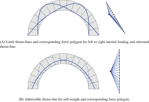
The form-finding methodology outlined above and detailed in McLean et al.25 starts with any standard geometry of minimum thickness for a given loading scenario. This minimum thickness algorithm can be used to generate the input to our form-finding process. The arch's limit thrust-line is then obtained for left to right loading and mirrored as shown in Figure 1(A) to take into account the multi-directionality of the earthquake hazard. Importantly, previous work has not been clear on the ability of the output to resist a load combination involving vertical gravity loads alone, for example, in the absence of lateral action, which is the most persistent design condition. By contrast, we are explicit in incorporating this verification into our algorithm by finding an admissible thrust-line for self-weight such that it passes through the three points of intersection of the lateral loading thrust-lines as depicted in Figure 1(B).

Once the first generation of optimized arches is obtained in the way described above, the limit thrust-line is assumed not to vary significantly between successive iterations, an assumption that is in line with our preliminary numerical observations. As such, we assume that the limit thrust-line will pass through the extrados of the right springing (for left to right horizontal loading) and search for an admissible thrust-line by moving the thrust-line's end point through the thickness of the left support starting from the intrados. If no thrust-line is found, the thickness of the arch should be increased (usually at increments), until an admissible limit thrust-line is found. A summary of the form-finding algorithm is given in Figure 3.
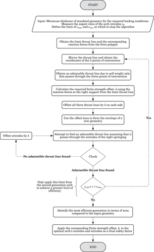
For the generation of each new optimal arch, the internal rise over span ratio is calculated and compared to that of the input geometry. As shown in McLean et al.,25 shallower arches () are more efficient at resisting lateral loads and as such the algorithm will tend towards shallower and thinner arches. Therefore, in order to prevent the span from increasing unboundedly, it is necessary to impose a geometry tolerance. In this paper, results are found for arch rise over span ratios within a 5% difference from the input geometry. This is a design decision that can be relaxed to achieve greater efficiencies if required.
3.2 Influence of input geometry
As the form-finding algorithm is based upon the limit thrust-line of standard geometries for a given loading, different input geometries will result in different form-found arches. Two main parameters can be used to compare the final outputs, namely, the material efficiency and the magnitude of the tensile force at the support. This latter parameter is of note since although parabolic arches are more material efficient than elliptical ones, they will tend to generate higher levels of horizontal thrust at the supports relative to their self-weight. The tensile forces that arise as a result are a key design consideration, especially in extraterrestrial environments where the foundation may be formed from compacted regolith with low tensile strength. To this end, tension forces are calculated from the horizontal reaction forces at the supports corresponding to the arch's limit thrust-line.
To create a frame of reference from which to compare the efficiency of different results, the areas, , and tensions, , are normalised by the corresponding results for elliptical (semicircular for ) arches of minimum thickness. The optimal elliptical (semicircular for ), parabolic and catenary arches of minimum thickness found in the previous section were run through our algorithm using one hundred blocks. Comparisons are offered for arches with internal rise of m and a maximum variation of with respect to the input value of .
Figure 4(A) compares the efficiencies of optimal form-found arches from different input geometries and varying levels of loading, quantified by the parameter introduced before. Efficiency is quantified as the ratio between the total in-plane area of the arch normalized by the corresponding area of the optimally thin semicircular counterpart, . As expected, the most efficient forms are found for low levels of lateral loading () due to the nearly symmetrical limit thrust-lines (minimal skewness) obtained for standard geometries under this conditions. It is also evident from Figure 4(A) that a semicircular input yields much less efficient arches by approximately 20%. This can be further appreciated in Figure 5, which presents a comparison of geometries for semicircular and catenary inputs for . In both cases, the limit thrust-lines correspond to two-springing four hinge mechanisms, and as such will pass through the intrados and extrados of the supports. This leads to very little change in the span of the arch during the form-finding process. However, we observed that the limit thrust-line of the semicircular arch passes tangent to the springing intrados at approximately 80 from the horizontal compared to 60 in the catenary case. Consequently, the limit thrust-line of the semicircular case is at a significant distance from the intrados at the crown of the arch resulting in the algorithm quickly reaching the rise over span ratio limit imposed. In the catenary case, its limit thrust-line passes very close to the crown of the arch and therefore the form-found arches maintain their rise over span ratio for more generations thus yielding a more efficient arch. The same effect is apparent in the parabolic arches explaining why the two give very similar form-found arches.
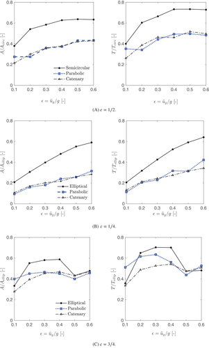

Similar results are obtained for different rise to span ratios as shown in Figure 4 for and . In this case, the optimal elliptical input area is used for area normalization purposes. This is the reason why for , the results show an apparent greater level of efficiency in comparison with Figure 4(A), since the elliptical minimum thicknesses is particularly inefficient compared to other geometries for long span structures, as discussed above. Besides, in the case of , there is a sudden discontinuity in the efficiency of the form-found arch from an elliptical input at . This is due to faster hinge rotation in steeper geometries discussed before, which causes the intrados hinge (non-springing) of the two-springing four hinge mechanism to approach the crown of an elliptical arch at . The limit thrust-line of the elliptical arch at these loads will then pass very close to the crown, ensuring that the resulting initial envelope of the first generation arch has a rise over span ratio much closer to that of the input geometry resulting in a greater number of generations and increased level of efficiency. It is therefore expected that this discontinuity will occur for elliptical arches of all aspect ratios, but only once the limit thrust-line passes close enough to the crown. This will take place at higher loads for shallower geometries as the hinge rotations are slower.
4 EFFECTS OF LOW-GRAVITY CONDITIONS
Under the Couplet–Heyman assumptions,1 the minimum thickness of masonry or monolithic arches of negligible tensile strength is solely dependent on the ratio of self-weight to inertial load . Therefore, optimal arches can be found for any gravitation field by introducing a gravitational multiplier,27 , with respect to the gravitational acceleration on Earth (i.e. m/s).
In this study, we assume that the strength of the lunar and martian gravitational fields are g and g, respectively.
Figure 6 shows the results for a range of demand ratios , an aspect ratio of and different gravitational fields corresponding to terrestrial, martian and lunar environments. As before, the efficiency of the arches is expressed in terms of ratios of areas and tension forces at the supports. The form-found arches take into account the finite strength of the material and hence they are not strictly self-similar for . However as the finite strength offset tends to be small in comparison with the thickness of the arch, the form-found arches for any demand ratio are very much alike. Only results for semicircular, parabolic and catenary inputs are presented since the elliptical inputs resulted in notoriously sub-optimal arches.
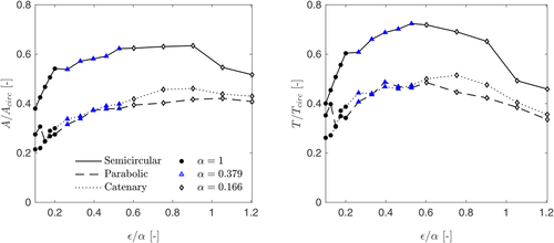
The results of Figure 6 show the material efficiency continuing to plateau as in Figure 4(A), however after , the semicircular results jump to a greater level of efficiency. The cause of this is the same as in Figure 4(C) where the thrust-line has flattened out enough such that it passes close to the crown and the resulting envelope has a similar rise and span to the input. This happens at a much higher loading because of the slower hinge rotations observed in shallower geometries. In addition, the results for tension induced at the supports show an increasing level of efficiency when compared to the circular results for high demand ratios. However this is an artefact of circular arches becoming very inefficient at these high loads. For both material efficiency and demand on foundations, form-found arches using a parabolic input yield the best results for arches subject to significant inertial loading. As demonstrated before for standard geometries, catenary inputs yield better results for very small levels of inertial loading in form-found arches as well. Overall, average material efficiencies of around 40% are observed. Similar results were obtained for other aspect ratios.
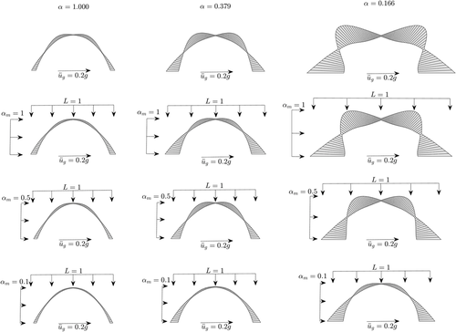
This effects of low gravity on the thickness variation along the arch under seismic action are clearly shown in Figure 7. This figure shows the optimal form-found arches with an internal rise of 10 m and for a design horizontal acceleration of g. In the lunar case, the shape is dominated by the extreme tilting of the thrust-line. It can also be seen from this figure that as the demand ratio increases the thickness variation throughout the arch becomes more significant. This is especially the case in low-gravity conditions, as the finite strength offset is still very small in comparison with the overall arch dimensions due to the smaller reaction forces. This may pose constructability issues in a monolithic structure due to large stress concentrations at the pinching points. A more practical thickness distribution can be obtained by offsetting the self-weight thrust-line by a larger amount during the form finding process, as discussed above. As an example, Figure 8 shows the last iteration of the form-finding algorithm when the self-weight thrust-line has been offset by 10% of the maximum thickness of the arch. Alternatively, the limit on the permitted rise over span ratio in the form-finding algorithm can be relaxed to allow more iterations and achieve a more rational shape as shown in Figure 9. This needs to be further investigated with the help of finite element analysis.


5 STABILIZING EFFECTS OF LOOSE REGOLITH SHIELDING
It is evident from our previous discussion that the effects of low gravity are akin to amplifying the effective inertial loading leading to larger arches. By applying additional mass over the top of the arch (loose regolith infill), vertical forces can be increased thus reducing the ratio of horizontal to vertical loads (). In this way, the asymmetry of an arch's thrust-line will be diminished and thinner geometries can be found. Within the context of extraterrestrial constructions, and in line with the In Situ Resource Utilization approach, loose regolith can be used as shielding to provide additional stabilising mass. This will have the added benefit of assisting with the minimum thickness requirements for radiation protection.28
However, the additional mass provided by the regolith shielding will exert some inertial actions during seismic events that may hamper its effectiveness and need to be accounted for. A precise consideration of the complex inertial interactions and nonlinear effects associated with the response of loose regolith overburden during seismic actions will defy the purpose of this paper, which is to use simplified procedures to identify preliminary optimal arch forms which can then be further analysed during the detail stages of the design. This infill–arch interaction can cause both active and passive pressures whose magnitude and direction will vary during the seismic action. However, a simplified modelling approach is adopted herein as described below. This modelling approach aims to capture the overall effects of the regolith overburden while allowing a broad screening of limiting cases and keeping the computational expense at a minimum and can therefore be used for the quick mapping of potentially feasible solutions at a preliminary design stage examined in this paper. In this respect, Kampas et al.24 have proposed the consideration of at least two limiting cases broadly associated with frequent and infrequent events (e.g. serviceability and ultimate limit state). The more frequent, low-intensity ground motions, can be associated with the loose regolith layer remaining largely attached to the structure while the more infrequent event may lead to yielding and its partial collapse. Given the uncertainties involved, the mass participation of the loose regolith shielding is treated parametrically in this study.
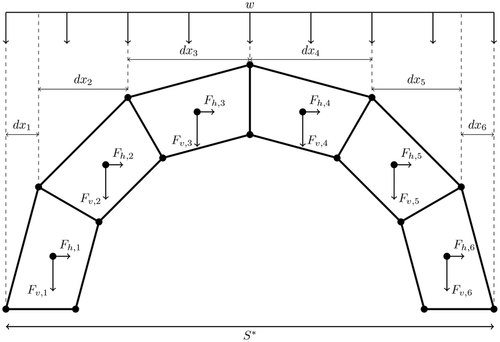
In order to model the additional mass of loose regolith shielding, a uniformly distributed load with potentially variable values per block length was adopted in this paper as indicated in Figure 10.
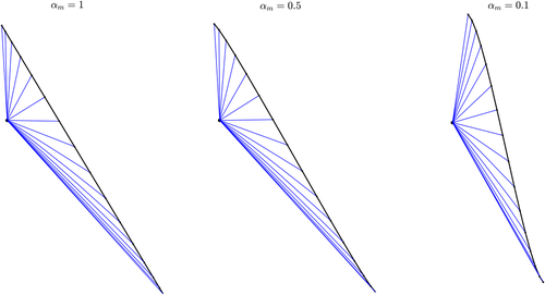
As the inertial contribution, quantified herein by the parameter introduced previously, is reduced, the load line of an arch subjected to uniformly distributed vertical loads steepens towards the middle. This is illustrated in Figure 11, which shows the effect of varying values of on the centroidal resultant forces of each voussoir of a classical parabolic arch. A steeper load line results in the inclination of the resultant thrust forces changing at a faster rate through the arch's length. Consequently, the thrust-line will be less broad resulting to thinner arches.
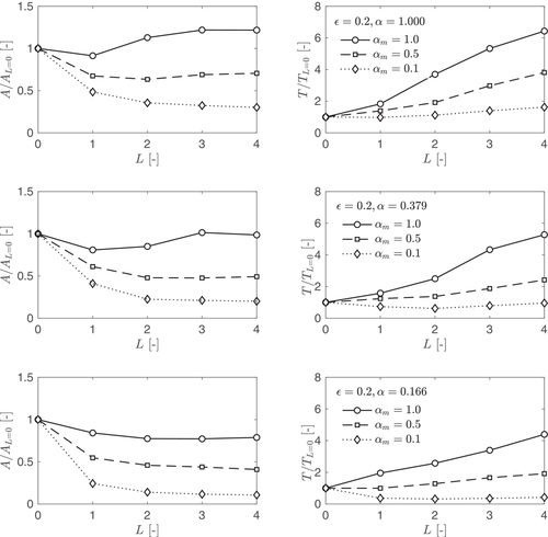
When there appears to be an optimal value of before the area begins to increase in Figure 12. However, this is only the case for the terrestrial and martian arches, whereas the lunar arch continues to get smaller under increased . This shows that the overburden is more effective for higher demand ratios, .
Figure 12 also shows that while the general effect of the overburden is to increase the material efficiency of the arch, this material efficiency comes at the cost of increased tensile loads induced at the supports. As previously mentioned, the foundations of these extraterrestrial structures are likely to be constructed from regolith with minimal tensile strength and this may be a limiting factor for the use of additional stabilising masses. For example, applying and for a ground acceleration of g: on earth the tension will increase by over six times its original value, compared to roughly five and four times in the martian and lunar cases, respectively. In some instances, a reduction of the tension forces can be observed with increased additional mass, but these occur for the limit case of only. However, Figure 12 shows that for the higher levels of inertial loading that will be seen in low-gravity conditions, the tension does not increase at the same rate as at the lower demand levels. Similar results were observed for and .
Figure 13 shows the effects of the overburden on the forms of the optimal form-found arches previously examined in Figure 7. The influence of the overburden is clearly seen from this figure where a more pronounced effect is evident for the lunar case with . These results also demonstrate that determining the true value of the inertial contribution, of the additional mass is of the utmost importance. The lower the inertial contribution, the more effective the additional vertical loads are at allowing the thickness of the crown to reduce as the thrust-lines become less broad.
6 PRACTICAL APPLICATION AND DEM VALIDATION
6.1 Case study geometries
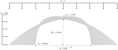
In order to illustrate the range of geometries that an optimal arch can take in extraterrestrial conditions, and compare the improvements brought about by the optimization algorithm described above, a case study is discussed in this section. This case study example covers the preliminary design of a shielding structure representing a potential storage facility subjected to seismic loading under the extreme lunar conditions (gravitational acceleration of g). A target rise of 15 m, target span of 30 m and design level lateral acceleration of 0.2g are considered. This level of acceleration is assumed in accordance with the observations of Oberst and Nakamura18 who compared the magnitude-recurrence relationships for shallow moonquakes with intraplate earthquakes in Central-Eastern United States. The structure is to be constructed from lunar regolith with density of 2.3 g/cm and maximum compressive strength of 4.2 MPa.26
For the demand ratio of , Figure 6 gives the most efficient input geometry as parabolic for a rise over span ratio, . Without any additional overburden, the minimum thickness of a CTA parabolic arch can be calculated as , for an internal rise of m this will correspond to a very large thickness of roughly m, thus highlighting the necessity of optimizing the arch's shape. As discussed before, the limit thrust line of the parabolic arch without any additional overburden has multiple curvatures that will manifest itself into large variations in the form-found geometries that can compromise its constructibility. As such it was decided to include a loose regolith overburden. This case study will proceed by assuming (as defined previously) and a relatively conservative inertial contribution of .24 The density of this loose regolith material is assumed to be the same as that of the arch structure as taken from Goulas et al.26
The final results of the form-finding process are presented in Figure 14 and Table 1. These results clearly demonstrate the effect of reducing the inertial contribution on the size of the form-found arch and highlight the need for rigorous optimization studies. By assuming that the loose regolith is of the same density as the 3D-printed regolith and is distributed uniformly across the arches span for , corresponds to overburden thicknesses of m.
| Parameter | Parabolic (CTA) | Form-found (VTA) | Reduction | |
|---|---|---|---|---|
| Tension generated at the supports | [] | 2482.4 | 873.2 | 65% |
| Area | [] | 399.1 | 212.9 | 47% |
6.2 Discrete element modelling and ground motion data-set
DE models were constructed in the commercial software UDEC29 using rigid blocks in conjunction with the Coulomb slip area model at the rigid block interfaces (represented by shear and normal joint springs) to account for the regolith's elastic modulus in an approximate way. The friction coefficient angle was set to 90 with the purpose of preventing sliding between blocks and to approximate a monolithic arch while the cohesion was set equal to 0 Pa.
Since the springs are considered to simulate the elasticity of the material while the blocks remain rigid, normal and the shear springs with the same elastic stiffness were employed. To this end, a value of 1.9e9 Pa/m was used for the dynamic analyses for both the shear () and normal joint stiffness (). This value was calculated by means of the expressions provided by DeJong30 and tested by DeJong and Vibert31 and Makris et al.32 It should be noted that while Makris et al.'s model represents a trilith, DeJong and Dimitrakopulos33 have shown that a trilith can approximate the response of arches.
A damping ratio of of the critical value at was adopted assuming zero mass damping at a centre frequency of =256 cycles/s,29 where is the edge impact frequency as defined in DeJong30 to avoid unwanted underdamped behaviour. On this basis, damping coefficients which were calculated using the expressions proposed by DeJong30 were found by Makris et al.32 to provide better results compared with experimental observations. It is recognized, however, that given the variety of block dimensions, further studies are needed in order to provide full experimental support for the damping models adopted. Those parameters were calculated for a mean size of each voussoir. Additionally, the values found by Goulas et al.26 for the Young's modulus of sintered regolith (without additives) of 287.3 MPa and its density = 2300 kg/m were adopted.
In order to perform the response history analyses, a set of 10 ground-motions were selected as summarized in Table 2. As mentioned before, Oberst and Nakamura18 first considered the concept of seismic hazard and risk for a potential lunar base. They discovered similar seismicity rates between the shallow moonquakes and the intraplate earthquakes on Earth. Importantly, according to their estimations, made on the basis of the occurrence rate, a potential lunar base constructed at a random location may be exposed to a shallow moonquake of magnitude above 4.5 M within a distance of 100 km once in 400 years. In this context, four recordings, detected at the vast area of Central and Eastern North-America, have been included in the dataset (Ns 7–10 in Table 2). Furthermore, six ground motions (Ns 1–6 in Table 2) recorded during a strong earthquake occurred at Pawnee, Oklahoma in 2016, are also included. All the above events, are characterized by magnitude M 5.5 and epicentral distance R 90 km. The average shear velocities of the recordings is higher than 360 m/s, which indicates stiff and rocky soils (e.g. type A and B according to Eurocode 834 provisions). All the pertinent details are contained in Table 2.
| N | Event | Station | Mw | Vs30 [m/s] | [g] |
|---|---|---|---|---|---|
| 1 | Pawnee 03/09/2016 | KAN09 | 5.8 | 396 | 0.046 |
| 2 | Pawnee 03/09/2016 | KAN14 | 5.8 | 701 | 0.047 |
| 3 | Pawnee 03/09/2016 | OK005 | 5.8 | 591 | 0.055 |
| 4 | Pawnee 03/09/2016 | OK030 | 5.8 | 448 | 0.057 |
| 5 | Pawnee 03/09/2016 | OK032 | 5.8 | 500 | 0.059 |
| 7 | Mineral 23/08/2011 | SE.NANPP | 5.74 | 554 | 0.264 |
| 8 | Nahanni 23/12/1985 | Nahanni, NT | 6.76 | 1700 | 1.340 |
| 9 | Nahanni 23/12/1985 | Nahanni, NT | 6.76 | 1700 | 0.542 |
| 10 | Nahanni 23/12/1985 | Nahanni, NT | 6.76 | 1700 | 0.194 |
6.3 Analysis and results
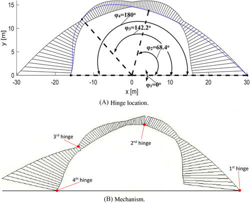
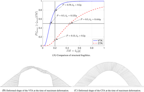
Figure 16 presents and compares the fragility curves obtained for the VTA and CTA arches together with their deformed shape at the time of maximum demand. This figure demonstrates that CTA arches, dimensioned to have minimum constant thickness have a substantial conservativeness associated with their seismic response reaching a conditional probability of exceedance of the of only for the design intensity of (associated with a LS exceedance probability of ). This large level of over-design is critical in the context of space exploration with limited availability of resources and critical energy demands. By contrast, the associated with the mean probability of exceedance of the for the VTA arch is g. This value is noticeably smaller than the 0.2 g assumed for its design, attributable to the rather stringent (material failure) assumed that does not always correspond to the formation of the full mechanism (geometric instability). Although comparisons between different modelling approaches are always complicated by the diversity of assumptions, this is a feature that should be the topic of further studies improving on the optimal VTA found by, for example, increasing the thickness in the pinching regions of the VTA informed by finite element investigations. It is also worth noting, that the variability of the response in VTA arches is reduced in comparison with their CTA counterparts, with coefficients of variation of 47% and 64%, respectively. Although it can be argued that an important part of this variability can be reduced by an ad hoc selection of ground-motion intensity measures, the comparative improvement of VTAs relative to CTAs hints to a better control of their seismic response produced by the optimization of their geometry.
7 CONCLUSIONS
This paper has investigated the optimal form of arches subjected to in-plane seismic loading under normal and extreme gravitational conditions. Under the Couplet–Heyman's assumptions, the stability of arches subject to inertial loading is dependent upon the ratio of vertical (self-weight) and horizontal (inertial) forces present in the structure. Hence, unless finite strength is taken into account, all arches are scalable. This means that the results and methods present herein have important implications for terrestrial applications as well, especially those where material efficiency is of utmost concern.
A form-finding algorithm has been implemented to produce optimal geometries for concurrent gravity and seismic loading. Importantly, we found that the output geometry is dependent upon the standard geometry of minimum thickness used as an input. This has important implications for the use of previously proposed optimization methods where more arbitrary selections of initial inputs were assumed. It was also shown that, similar to standard geometries, a parabolic input generally produces more optimal arches both in terms of material usage and tensile loads induced at the supports. Parabolic input achieves at least a 50% reduction in both material usage and tensile load under high levels of seismic loading for all aspect ratios considered and the material savings can be as high as 90% for lower seismic intensities.
The effect of low gravity is to effectively amplify the demand exerted on the structure by reducing its self-weight, which acts as the stabilising force when an arch is subject to lateral loads. This makes the design of structures to resist lateral loads in lunar environments the critical scenario as the strength of the gravitational field is approximately 17% of that on Earth. However, due to the aforementioned scalability of results, the comparison between different geometries and aspect ratios remains valid.
The use of additional loose regolith placed over the top of the structure to counteract the loss of self-weight due to low-gravity and to reach to the minimum thickness for radiation protection was explored. Our results show that the effectiveness of the overburden is heavily dependent upon the assumed inertial contribution of the additional mass revealing the need for a detailed design consideration. Although generally thinner arches are obtained when overburden is added, the additional mass can also lead to increased levels of tension induced at the foundations.
A case study has been presented where the response of a VTAs of optimal geometry is compared against its minimum constant thickness (CTA) counterpart by means of DEM and using the peak ground acceleration as and a material failure strain level as . The results of the response history analyses were summarized in fragility functions that highlighted the important over-conservativeness of CTA. By contrast, the VTA exhibited a higher probability of exceedance of for the design-level g. Although this result point towards the need for geometry improvements that take into account the potential for localized stress concentrations, the comparatively low variability in the response of the VTA in comparison with the CTA hint to an improved control on their dynamic response under seismic action.
ACKNOWLEDGEMENTS
Drs. Kalapodis and Kampas wish to acknowledge the support of the UK Engineering and Physical Sciences Research Council (EPSRC) through the grant EP/S036393/1.
Open Research
DATA AVAILABILITY STATEMENT
The data and MatLab scripts employed in this work are available from the corresponding author upon request.


