Comparison Between Analytical Models for Predicting the Long-Term Behavior of Cracked Reinforced Concrete Beams
ABSTRACT
Predicting the long-term deflection of reinforced concrete (RC) beams is a critical aspect of structural engineering to ensure the safety, serviceability, and durability of concrete structures. Deflection predictions are influenced by several factors like material properties, environmental conditions, and loading history, and require comprehensive models that account for the complex, time-dependent nature of concrete behavior. This study evaluates three analytical models for predicting long-term deflection in cracked RC beams: the Adjusted Step-by-Step Method (SSM-Adjusted), the Adjusted Age-Adjusted Effective Modulus Method (AEMM-Adjusted), and a newly developed Proposed Model. While SSM and AEMM are classical approaches adapted here to account for cracking and nonlinear behavior, the Proposed Model is an original contribution by the authors. The validity of all three models was verified by comparing analytical results with experimental data from numerous RC beams found in the literature. The comparison revealed a high level of compatibility and satisfactory agreement between the models and experimental results.
1 Introduction
Long-term deflection in reinforced concrete (RC) beams is a critical element in structural design due to its direct impact on safety and serviceability. Temporal deflection often exceeds instantaneous deflection, especially in cracked members or members reinforced with materials such as CFRP, where it can reach 1.42–1.45 times the initial deflection [1]. High-strength concrete also exhibits different behavior with a lower creep coefficient and time deflection compared to plain concrete, necessitating an update of current models [2]. Accurate deflection prediction is increasingly important in sensitive structures such as prestressed bridges with large spans, due to the impact of creep and loss of prestress on structural performance [3]. These data underscore the need to develop improved models that take into account material type and operating conditions to effectively control deflection.
Predicting long-term deflection in RC beams is a significant challenge due to the complex interactions between material properties, structural behavior, and environmental factors. Conventional models struggle to represent creep, shrinkage, and cracking, especially in high-strength, fiber-RC, which can lead to errors of up to 70% [2, 4, 5]. The complexity also increases when dealing with recycled or cracked members, and under dynamic loads or cross-sectional changes, such as in long-span bridges and high-strength columns [3, 6, 7]. These challenges highlight the need for more sophisticated analytical models and innovative sensing technologies to improve the accuracy of predicting the long-term behavior of concrete structures.
The Step-by-Step method (SSM) is a precise analytical method used to predict long-term deflection in RC beams. This method is based on a gradual update of the time-deformation state, allowing accurate tracking of behaviors such as creep, shrinkage, and changes in material properties over time. It has proven effective in applications requiring high accuracy in monitoring the evolution of deflection. Motter and Scanlon [8] demonstrated the effectiveness of the SSM in calculating the creep effect, providing fundamental equations that influenced subsequent studies. Valivonis [9] also demonstrated its adaptability to beams with non-metallic reinforcement, while Choi [10] highlighted its use in high-strength RC slabs and defined minimum thickness requirements. These studies, along with ongoing developments, reflect the importance of the SSM as a reliable tool in the design and analysis of RC structures to ensure their long-term performance and safety.
The Age-Adjusted Effective Modulus Method (AEMM) method is a structural engineering method for predicting long-term deflection in RC structures. It incorporates the effects of creep and shrinkage over time by adjusting the elastic modulus according to the age of the concrete. This approach is simple and accurate in modeling behavior under sustained loads. Gilbert and Ranzi [11] highlighted the use of AEMM in RC columns and beams, demonstrating its importance in serviceability assessment. Feng et al. [12] demonstrated its effectiveness in analyzing nonlinear creep in externally prestressed beams, in clear agreement with experimental results. The applications of AEMM have expanded to include various structural cases. Dabarera et al. [13] reviewed its role in high-performance concrete and the effect of sustained loads on the elastic modulus in the early stages. Gao and Bradford [14] demonstrated its effectiveness in predicting axial shortening and lateral displacement in columns. Chen et al.'s work [15] also confirmed its role in predicting stress redistribution and deflection in concrete-steel composite structures. Together, these studies reflect the reliability of AEMM as an accurate and flexible analytical tool in evaluating time deformation in various construction systems and materials.
Recent research has focused on improving analytical models for predicting the long-term behavior of RC beams by incorporating the effects of cracking, nonlinear material behavior, and varying environmental conditions. Several studies, such as Wei et al. [16] and Al-Marhala et al. [17], have shown that conventional models such as ACI 209 and Eurocode 2 exhibit limitations in accurately representing creep and deflections, especially when using FRP or synthetic fiber reinforcement, necessitating the development of modified models more compatible with these materials. Tang et al. [18] also demonstrated that beams damaged by fatigue or corrosion exhibit high short-term creep and presented an exponential model to improve predictions. For recycled concrete, Chen et al. [19] developed time-reduction factors that reflect its changing properties, while Havlasek et al. [20] indicated that the Microprestress-Solidification (MPS) theory overestimates creep under moisture fluctuations and does not capture nonlinear shrinkage relationships. Miàs et al. [21] also developed simplified bending models for GFRP beams, which improved predictions but remained based on experimental data. Together, these efforts underscore the need for more accurate and flexible models that can handle a variety of materials, reinforcement systems, and operating conditions to ensure reliable prediction of long-term behavior.
Current analytical models often fall short in capturing the complexities of cracked RC beams, which exhibit distinct behaviors such as tension stiffening, reduced stiffness, and nonlinearity due to cracking. Traditional models, while effective for non-cracked states, fail to incorporate critical parameters like crack width, spacing, and propagation, leading to inaccuracies in predictions of long-term deflections and structural responses [22, 23]. The need to adapt and extend these models is underscored by studies showing that cracking fundamentally alters the stress–strain relationships and load-bearing capacities of RC structures [24, 25]. Moreover, validating these adapted models is crucial for improving predictions and ensuring structural safety, as cracking significantly impacts durability and serviceability, especially under sustained or cyclic loading [26, 27]. Extending models to accurately reflect cracked behavior enables more reliable simulations and designs, addressing gaps in current practices.
In early 2023, the authors presented an analytical model to predict the performance of RC beams under permanent service loads. This provides accurate predictions of both immediate and long-term behavior [28]. To estimate the height and width of cracks during creep, the concrete stress–strain equations in tension and compression were modified and applied to the EMM technique, resulting in a good prediction of cracks. The Effective Modulus Method (EMM) estimates long-term deflections in concrete by simplifying creep effects through a modified modulus of elasticity [28]. In 2024, the authors also investigated the optimal creep coefficient calculation method for RC beam long-term results, as well as the effect of the creep function integration approach on prediction results by adjusting the AEMM to account for beam cracking [29]. This paper completes the work begun earlier by the authors and summarizes the results of all the studies carried out, comparing the results with those of about 40 beams studied in various studies published in the literature.
This study aims to provide a comprehensive evaluation of three analytical models—the Proposed Model, the Age-Adjusted Effective Modulus Model (AEMM-Adjusted), and the SSM-Adjusted—for predicting the long-term behavior of cracked RC beams subjected to sustained bending moments. By incorporating the nonlinear behavior of materials and the cracked state of concrete, the models offer enhanced accuracy compared to traditional approaches. The novelty of this work lies in the integration of advanced creep coefficient calculation methods derived from Eurocode 2 [30], fib Model Code 2010 [31], and ACI 209 [32] guidelines, allowing for a detailed comparison using experimental data from 52 beams documented in the literature. The findings underscore the critical influence of the adopted creep coefficient methodology on prediction accuracy and establish the Proposed Model as a robust tool for addressing the complexities of cracked RC behavior over time. This study contributes significantly to improving the precision of long-term deflection forecasts, ensuring better serviceability and durability of concrete structures.
2 The Database
A database containing 52 beams has been gathered from several research studies conducted to investigate the creep effect of beams under sustained load [17, 21, 33-46]. Table 1 summarizes this database and shows the main data of each study.
| References | No. of beams | ID | [%] | RH [%] | Temp [°C] | Ag [cm × cm] | Span [m] | fcm [MPa] | ρ [%] | tLoading [days] | ΔCreep [mm] |
|---|---|---|---|---|---|---|---|---|---|---|---|
| Leone et al. [33] | 1 | OPC | 45.45 | 45 | 22 | 20 × 20 | 2.8 | 35.6 | 1.54 | 462 | 7.7 |
| Marahla et al. [17] | 2 | F0D16 | 48.97 | 45 | 22 | 20 × 26 | 3.05 | 60.3 | 0.77 | 90 | 5 |
| F0D20 | 48.86 | 45 | 22 | 20 × 26 | 3.05 | 60.3 | 1.21 | 90 | 4.2 | ||
| Cao et al. [34] | 4 | D0/0L | 25.51 | 55 | 20 | 20 × 30 | 3.00 | 35.9 | 1.03 | 744 | 1.54 |
| D0/0H | 44.99 | 55 | 20 | 20 × 30 | 3.00 | 35.9 | 1.03 | 744 | 1.78 | ||
| G0/0L | 32.64 | 55 | 20 | 20 × 30 | 3.00 | 63.9 | 1.03 | 744 | 1.49 | ||
| G0/0H | 52.11 | 55 | 20 | 20 × 30 | 3.00 | 63.9 | 1.03 | 744 | 1.62 | ||
| Stojkoska et al. [35] | 6 | St-A | 46.45 | 30 | 25 | 15 × 26 | 2.80 | 40.82 | 0.60 | 325 | 2.5 |
| St-B | 50.41 | 30 | 25 | 15 × 26 | 2.80 | 40.82 | 0.60 | 325 | 3.36 | ||
| St-C | 54.37 | 30 | 25 | 15 × 26 | 2.80 | 40.82 | 0.60 | 325 | 3.3 | ||
| St-D | 58.38 | 30 | 25 | 15 × 26 | 2.80 | 40.82 | 0.60 | 325 | 3.42 | ||
| St-E | 62.24 | 30 | 25 | 15 × 26 | 2.80 | 40.82 | 0.60 | 325 | 2.61 | ||
| St-F | 66.36 | 30 | 25 | 15 × 26 | 2.80 | 40.82 | 0.60 | 325 | 3.53 | ||
| Li et al. [36] | 5 | LD-A-1 | 35.97 | 60 | 15 | 12 × 15 | 1.90 | 51 | 1.26 | 331 | 1.57 |
| LD-B-1 | 35.97 | 75 | 15 | 12 × 15 | 1.90 | 51 | 1.26 | 331 | 1.11 | ||
| LD-B-2 | 35.97 | 75 | 15 | 12 × 15 | 1.90 | 51 | 1.26 | 331 | 1.17 | ||
| LD-C-1 | 35.97 | 80 | 15 | 12 × 15 | 1.90 | 51 | 1.26 | 331 | 0.86 | ||
| LD-C-2 | 35.97 | 80 | 15 | 12 × 15 | 1.90 | 51 | 1.26 | 331 | 0.76 | ||
| Seara-Paz et al. [37] | 1 | H65 | 45.54 | 73 | 14 | 20 × 30 | 3.4 | 50.3 | 0.67 | 1300 | 4.87 |
| Tošic et al. [38] | 1 | NAC7 | 52.35 | 48 | 21 | 16 × 20 | 3.2 | 32.9 | 0.49 | 450 | 9.62 |
| Sryh and Forth [39] | 1 | NC | 50.77 | 45 | 20 | 30 × 15 | 4.0 | 41.5 | 1.34 | 90 | 18.3 |
| Tim Van Mullem et al. [40] | 10 | B1-L72 | 72.00 | 60 | 20 | 15 × 28 | 2.8 | 39.7 | 0.73 | 1638 | 4.27 |
| B1-L81 | 81.00 | 60 | 20 | 15 × 28 | 2.8 | 39.7 | 0.73 | 1372 | 4.59 | ||
| B1-L91 | 91.00 | 60 | 20 | 15 × 28 | 2.8 | 39.7 | 0.73 | 1342 | 6.08 | ||
| B2-L52 | 52.00 | 60 | 20 | 15 × 28 | 2.8 | 35 | 1.83 | 1426 | 6.22 | ||
| B2-L59 | 59.00 | 60 | 20 | 15 × 28 | 2.8 | 35 | 1.83 | 1569 | 6.41 | ||
| B2-L70 | 70.00 | 60 | 20 | 15 × 28 | 2.8 | 35 | 1.83 | 1499 | 8.2 | ||
| B2-L80 | 80.00 | 60 | 20 | 15 × 28 | 2.8 | 35 | 1.83 | 1513 | 9.52 | ||
| B3-L43 | 43.00 | 60 | 20 | 15 × 28 | 2.8 | 40.3 | 2.93 | 1600 | 7.43 | ||
| B3-L67 | 67.00 | 60 | 20 | 15 × 28 | 2.8 | 40.3 | 2.93 | 1600 | 13.3 | ||
| B3-L77 | 77.00 | 60 | 20 | 15 × 28 | 2.8 | 40.3 | 2.93 | 1600 | 14.9 | ||
| Masmoudi et al. [41] | 1 | Mas | 7.41 | 45 | 20 | 15 × 20 | 1.7 | 30 | 0.75 | 300 | 0.26 |
| Shariq et al. [42] | 11 | B11C25 | 21.19 | 40 | 20 | 10 × 15 | 1.7 | 46.51 | 0.67 | 150 | 0.8 |
| B21C25 | 17.71 | 40 | 20 | 10 × 15 | 1.7 | 37.03 | 0.67 | 150 | 0.95 | ||
| B31C25 | 14.22 | 40 | 20 | 10 × 15 | 1.7 | 27.09 | 0.67 | 150 | 0.93 | ||
| B11C50 | 42.37 | 40 | 20 | 10 × 15 | 1.7 | 46.51 | 0.67 | 150 | 1.7 | ||
| B21C50 | 35.41 | 40 | 20 | 10 × 15 | 1.7 | 37.03 | 0.67 | 150 | 1.92 | ||
| B31C50 | 28.45 | 40 | 20 | 10 × 15 | 1.7 | 27.09 | 0.67 | 150 | 1.95 | ||
| B12C25 | 15.57 | 40 | 20 | 10 × 15 | 1.7 | 46.51 | 1.04 | 150 | 1.15 | ||
| B22C25 | 13.61 | 40 | 20 | 10 × 15 | 1.7 | 37.03 | 1.04 | 150 | 1.34 | ||
| B32C25 | 11.78 | 40 | 20 | 10 × 15 | 1.7 | 27.09 | 1.04 | 150 | 1.42 | ||
| B12C50 | 31.14 | 40 | 20 | 10 × 15 | 1.7 | 46.51 | 1.04 | 150 | 2 | ||
| B22C50 | 27.75 | 40 | 20 | 10 × 15 | 1.7 | 37.03 | 1.04 | 150 | 2.3 | ||
| Choi and Yun [43] | 1 | CHOI-B | 50.00 | 70 | 15 | 17 × 20 | 2.0 | 31.61 | 0.46 | 380 | 1.1 |
| Shubaili et al. [44] | 2 | B2-SL | 78.33 | 55 | 15.4 | 14 × 14 | 1.2 | 42.45 | 0.80 | 25 | 1.11 |
| B4-SL | 89.24 | 55 | 16.5 | 14 × 14 | 1.2 | 42.45 | 0.80 | 24 | 2.18 | ||
| Mias et al. [21] | 3 | N-L1-S10 | 29.26 | 45 | 24 | 14 × 19 | 2.2 | 27.7 | 0.59 | 250 | 2.98 |
| H-L1-S10 | 47.73 | 43 | 23 | 14 × 19 | 2.2 | 56 | 0.59 | 700 | 3.05 | ||
| H-L2-S10 | 61.76 | 43 | 23 | 14 × 19 | 2.2 | 56 | 0.59 | 700 | 3.76 | ||
| Fawzi et al. [45] | 2 | RB2A-10 | 79.01 | 65 | 20 | 20 × 25 | 1.8 | 43 | 0.31 | 460 | 0.88 |
| RB2A-6 | 73.66 | 65 | 20 | 20 × 25 | 1.8 | 31 | 0.31 | 460 | 2.35 | ||
| Jiang et al. [46] | 1 | J-B-1 | 57.75 | 73 | 21.5 | 25 × 40 | 2.9 | 41.9 | 0.46 | 300 | 1.37 |
The studies employed long-duration experiments on RC beams to capture time-dependent behavior under sustained loading. Several works focused on recycled aggregate concrete (RAC) and other sustainable concrete mixes, such as high-volume fly ash concrete and hybrid normal-weight/lightweight concrete, by subjecting beams to sustained loading for periods ranging from 1 to 3.5 years [34, 37-40]. In contrast, other researchers investigated beams with innovative reinforcement materials, such as glass fiber reinforced polymer (GFRP) and carbon fiber reinforced polymer (CFRP) [41-43]. One study tested CFRP-strengthened pre-cracked beams to evaluate how initial damage influenced long-term deflections over a 300-day period [46]. These beams were preloaded to induce varying degrees of cracking, subsequently reinforced with CFRP plates, and then subjected to sustained loading at 75% of their ultimate capacity [46]. Throughout the studies, deflections, strains, and crack development were monitored periodically, and many included companion specimens for creep and shrinkage measurements [37-39]. Some studies examined reinforcement type and amount, particularly comparing GFRP-reinforced beams against conventional steel-reinforced beams [42-44]. The analytical approaches included modifications to existing design codes, such as adjustments to Eurocode 2's tension stiffening factor and ACI 318 deflection formulas [21, 35, 45]. Jiang et al. introduced a new perspective by evaluating the effect of pre-cracking, showing that pre-cracked CFRP-strengthened beams exhibit lower long-term deflection compared to intact reinforced beams [46]. Other studies, such as Leone et al. [33] and Li et al. [36], have investigated the influence of materials and environmental conditions on the long-term performance of RC beams. Leone et al. [33] showed that the use of calcium sulfoaluminate (CSA) cement at high replacement ratios enhances stiffness and reduces creep and shrinkage compared to conventional cement, highlighting the need to update existing predictive models to account for this behavior. On the other hand, Li et al. [36] showed that moisture fluctuations, particularly short wetting and drying cycles, effectively limit creep and deflection, which is not accurately reflected by models such as ACI 209R and CEB-FIP90. These findings highlight the need to develop design models that include sustainable materials and actual environmental conditions.
Despite the diversity in materials and test conditions, the studies consistently showed that beam deflections increased over time due to creep and shrinkage. Most beams experienced a mid-span deflection roughly twice the initial value over the test period [39-41]. RAC mixtures displayed slightly higher creep-induced deflections than natural aggregate concrete, with greater stiffness loss at higher replacement levels [37-40]. However, deflections in RAC beams remained within acceptable serviceability limits [39]. Jiang et al. found that pre-cracked CFRP-reinforced beams exhibited a unique behavior: while pre-cracking did not significantly affect immediate deflection, it reduced long-term deflections by limiting additional creep deformations [46]. Under high sustained loads, creep effects were exacerbated, with deflections rising from 51% to 65% of total deformation when load levels increased from 25% to 50% of cracking load [42]. Beams with higher reinforcement ratios showed higher total-to-instantaneous deflection ratios, indicating that while heavier reinforcement reduced initial deflection, it did not proportionally mitigate long-term deflection growth [43, 44]. The effect of pre-cracking on CFRP-reinforced beams was particularly notable: beams with larger initial cracks experienced less long-term deflection due to stress redistribution within the CFRP layers [46]. Under extreme sustained loading (˜98% of ultimate capacity), tertiary creep and failure occurred, with a 190% increase in deflection at failure compared to the initial condition [21]. However, most studies confirmed that long-term loading did not significantly reduce ultimate bending capacity [45].
The studies provide significant design implications, particularly for sustainable concrete applications and advanced reinforcement strategies. The findings support the use of RAC, as deflections were only slightly higher than those in conventional concrete, and ultimate load-bearing capacity remained comparable [39, 40]. However, designers should consider the slightly greater residual (irrecoverable) deflection observed in RAC beams—one study showed that RAC beams recovered only 11%–22% of their deflection upon unloading, compared to 23%–26% in natural aggregate concrete [41]. The results of Jiang et al. emphasize that pre-cracking should not necessarily be seen as a disadvantage in CFRP-strengthened beams, as it can reduce creep-related deflections [46]. Modifications to design codes were proposed based on these findings, such as reducing the Eurocode 2 tension stiffening factor from 0.5 to 0.3 for 100% RAC beams, which improved prediction accuracy [21]. Additionally, long-term behavior assessments of GFRP-RC indicated that creep effects were less pronounced than in steel-RC [42]. However, researchers cautioned against excessive reinforcement, as heavier reinforcement ratios led to a higher proportion of long-term deflection within the total deformation [43]. Jiang et al. further highlighted that pre-cracked CFRP-reinforced beams develop fewer new cracks over time, enhancing durability under service loads [46].
Together, these 16 studies significantly advance the understanding of long-term deflection in RC beams, particularly in the context of sustainable materials and innovative reinforcement techniques. The combined findings demonstrate that creep and shrinkage effects can be reliably predicted when factors like aging, tension stiffening, and reinforcement type are properly accounted for [40, 45]. The studies validate that RAC, GFRP, and CFRP reinforcements are viable solutions for durable structural applications, provided their specific creep and shrinkage characteristics are considered in design [44]. Notably, Jiang et al. provided a crucial insight: pre-existing cracks do not necessarily lead to greater long-term deflections, as CFRP reinforcement effectively redistributes stress, reducing creep-related deformations [46]. Engineers and code developers can use these results to refine creep and shrinkage prediction models and ensure long-term deflections and crack widths remain within acceptable limits [21, 45]. The comprehensive dataset from these studies provides valuable benchmarks for future experimental validation and analytical modeling efforts aimed at improving deflection predictions in advanced concrete structures.
3 The Long-Term Behavior of RC Beams
The authors developed three analytical models—the “Proposed Model,” the “AEMM-Adjusted,” and the “SSM-Adjusted”—to investigate the creep response of RC beams subjected to a sustained bending moment. While the “AEMM-Adjusted” and “SSM-Adjusted” models were derived from a fundamental model available in the literature [11, 47], the “Proposed Model” was developed entirely by the authors [28]. Each model captures the material's nonlinear behavior, as detailed in Bakleh et al. [28, 29].
3.1 Materials' Adopted Models
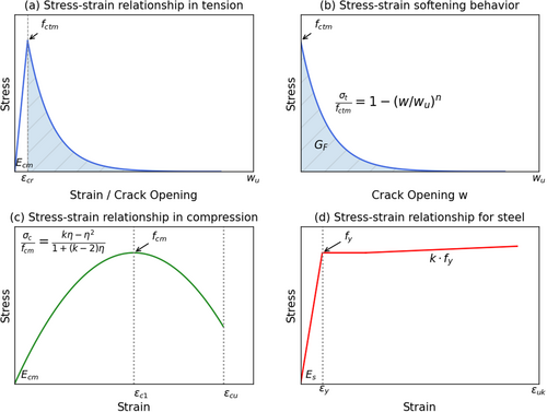
4 Creep Analytical Models
4.1 The Proposed Model (Instantaneous and Long-Term)
Accurately predicting the instantaneous performance of RC members is essential for reliably anticipating their long-term creep behavior. The proposed model is designed to calculate the initial deflection of a simply supported beam subjected to four-point bending under any given permanent loading magnitude. The authors previously modified and detailed this model in an earlier study [28].
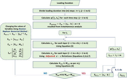
To account for the nonlinear behavior of materials, the model utilizes Bernoulli's hypothesis and the equilibrium conditions of the beam to evaluate the stress and strain distribution across its cross-section. It specifically focuses on the strain of the central fiber (ε0) and the curvature (κ). The conceptual framework of the model is illustrated in Figure 2, while Equation (3) defines the relationship between ε0, κ, and the strain ε at any given fiber as a function of y, which represents the distance between the section's bottom and the fiber under consideration (Figure 3).
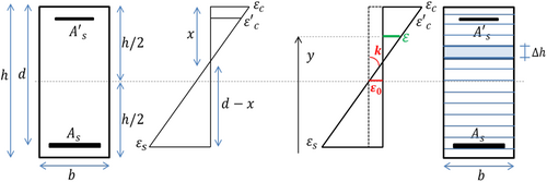
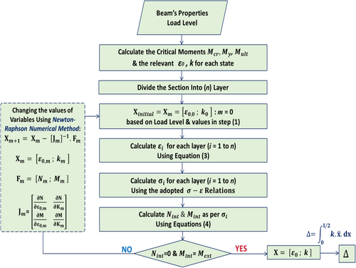
By applying Equation (3), the strain at each fiber can be determined, allowing the corresponding material behavior laws to be used in calculating the stress at each fiber. The equilibrium equations governing internal and external loads, as well as the bending moment (Equation 4), are then solved to determine the neutral axis location and, consequently, the unknown parameters (ε0 and κ). Due to the highly nonlinear nature of these equations, numerical solutions are required. Figure 2 provides an overview of this computational process. Using the curvature (κ) and the position (), measured from the left support along the beam span, the mid-span deflection can be determined.
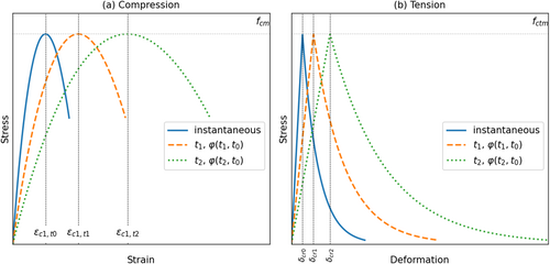
A collected data from 52 experimental beams found in literature have been used for an extended assessment of the proposed model. In addition, a comparison between this model and two major creep models found in the references used in Table 1 is given in the following sections.
4.2 The AEMM-Adjusted Model
4.3 The SSM-Adjusted Model
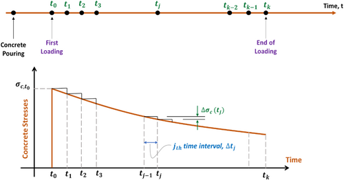
The basic step-by-step (SSM) model has been clarified in detail by Gilbert and Ranzi [11]. This method becomes more useful when the stress history is not constant, and this is the case in RC beams' creep problem as mentioned previously. The methodical process entails discretizing the time domain into several instants (Figure 8). The structural response is computed at every time instant sequentially, with the solution at each time instant depending on the results obtained from the preceding time instants.

5 Models Comparison and Assessment
The primary objective of this study is to conduct a comprehensive comparison of the three analytical creep models under investigation. This is achieved by evaluating the creep deflection results generated by these models against the actual long-term deflections observed in 52 experimental beams documented in the literature, as presented in Table 1. The accuracy of each model was assessed by calculating its correlation coefficient, providing a quantitative measure of how well the predicted values align with experimental data.
One of the key findings from the authors' previous work [29] highlighted that the selection of a creep coefficient model significantly impacts the overall accuracy of deflection predictions. To further investigate this influence, three widely recognized analytical models for creep prediction—Eurocode 2 (EC2) [30], fib Model Code 2010 (fib MC2010) [31], and ACI-209 [32]—were employed in the comparison. Figures 10-12 illustrate the correlation coefficients obtained for each of these standards when applied to the three analytical models: the Proposed Model, the SSM-Adjusted Model, and the AEMM-Adjusted Model.


A detailed examination of these figures reveals several important observations. First, as depicted in Figures 10-12, all three models exhibit relatively convergent values of the correlation coefficient for each creep standard. This indicates that, irrespective of the selected creep prediction standard, the models demonstrate a consistent level of accuracy in replicating experimental results. However, some variations exist in the degree of agreement, which highlights the influence of the underlying assumptions in each creep model.
Second, a comparative analysis of Figures 10-12 underscores the substantial effect that the choice of creep coefficient model has on the final predictions. The correlation coefficient varies depending on whether EC2, fib MC2010, or ACI-209 is used, suggesting that certain models may be more suitable for specific cases. This finding aligns with prior research [29], which identified the sensitivity of deflection predictions to the adopted creep formulation.
Among the three creep models, the ACI-209-based predictions (Figure 12) exhibit the largest deviations from experimental results. This is primarily due to the absence of key parameters required for accurate creep coefficient estimation, such as concrete mixture composition, air content, slump, and curing methods. These parameters play a crucial role in capturing the time-dependent behavior of concrete, and their omission in ACI-209 leads to greater discrepancies between predicted and actual deflections. Consequently, while ACI-209 remains a widely used model in engineering practice, it may require further adjustments or supplementary data to improve its accuracy when applied to experimental cases. Figures 10 and 11 illustrate that the EC2 and fib MC2010 models yield relatively closer agreement with experimental deflections compared to ACI-209. Between these two, the fib MC2010 model appears to provide slightly better correlation coefficients in certain cases, likely due to its more refined approach in modeling long-term concrete behavior. Nonetheless, both models present viable options for practical applications, offering improved predictive capabilities over ACI-209.
A further breakdown of Figures 10-12 reveals that the Proposed Model generally achieves the highest correlation coefficient across all three creep standards, indicating its superior ability to capture the long-term deflection behavior of RC beams. The SSM-Adjusted and AEMM-Adjusted Models also perform well, but their accuracy fluctuates depending on the creep standard employed. This suggests that while these models provide reasonable approximations, their performance could benefit from refinements tailored to the specific creep formulation being utilized. In conclusion, this comparative analysis confirms that the selection of a creep coefficient model plays a critical role in determining the accuracy of long-term deflection predictions. The findings indicate that EC2 and fib MC2010 generally outperform ACI-209 due to their more detailed parameterization of concrete behavior. Additionally, the Proposed Model consistently demonstrates the best correlation with experimental data, reinforcing its robustness in predicting creep-induced deflections. Future studies may focus on further optimizing these models by incorporating additional experimental data and refining the calibration of creep coefficients to enhance their predictive capabilities.
This superior performance can be attributed to the Proposed Model's comprehensive treatment of material nonlinearity and cracking effects, which are often simplified or partially addressed in the adjusted AEMM and SSM models. Unlike the other two models, the Proposed Model integrates a refined stress–strain relationship for both tension and compression zones and directly incorporates the cracked section's behavior into the long-term analysis. As a result, it more accurately reflects the actual structural response under sustained loading, leading to higher correlation coefficients with experimental results, as shown in Figures 10-12.
The performance comparison of the proposed model, the SSM method, and the AEMM method across the EC2, fib, and ACI models reveals that the proposed model consistently delivers the highest predictive accuracy, particularly when paired with the fib and EC2 models, achieving an R2 of 0.950 and the lowest RMSE of 0.84 mm (Table 2). The AEMM method closely follows, showing slightly better MAE values (as low as 0.68 mm) but marginally higher RMSE and slightly lower R2. The SSM method, while still effective, consistently ranks third, with the lowest R2 values and the highest error metrics across all three modeling approaches. Overall, the proposed model demonstrates superior reliability and precision in predicting creep deflection, especially when used with the fib or EC2 models.
| Method | ACI | fib MC2010 | EC2 | ||||||
|---|---|---|---|---|---|---|---|---|---|
| R2 | MAE | RMSE | R2 | MAE | RMSE | R2 | MAE | RMSE | |
| Proposed model | 0.715 | 1.31 | 2.00 | 0.950 | 0.69 | 0.84 | 0.950 | 0.69 | 0.84 |
| SSM method | 0.645 | 1.39 | 2.23 | 0.937 | 0.72 | 0.94 | 0.937 | 0.72 | 0.94 |
| AEMM method | 0.667 | 1.38 | 2.16 | 0.945 | 0.68 | 0.87 | 0.945 | 0.68 | 0.87 |
6 Conclusions
- The EMM, AEMM, and SSM methods produced nearly identical results under constant loading conditions, demonstrating their reliability for long-term deflection analysis.
- The EC2 and fib MC2010 models provided highly consistent and accurate predictions. The ACI 209 model showed significant deviations due to its exclusion of key material properties (e.g., concrete composition, curing conditions); this point highlights the enormous and essential importance of accurately estimating the creep coefficient when predicting time-dependent deflections.
- The Proposed Model achieved almost the highest correlation with experimental results, proving to be the most robust approach by virtue of its superiority in dealing with a physical problem; that means it deals with stress–strain behavior relations. So, it is more tangible and more reliable. The AEMM-Adjusted and SSM-Adjusted Models also performed well but exhibited sensitivity to the choice of creep model, suggesting room for refinement.
- Direct experimental determination of creep coefficients is crucial for improving long-term deflection predictions, particularly in complex structural and environmental conditions.
- Investigating the effects of environmental factors (humidity, temperature) on creep behavior
- Incorporating real-time monitoring techniques (e.g., sensor-based deflection tracking) for model validation
- Exploring machine learning and hybrid analytical-experimental approaches for enhanced predictive capabilities
Author Contributions
Bassel Bakleh: software, formal analysis, writing – original draft, investigation. George Wardeh: conceptualization, methodology, software, supervision, writing – review and editing. Hala Hasan: methodology, supervision, resources. Ali Jahami: methodology, writing – original draft, writing – review and editing, investigation.
Conflicts of Interest
The authors declare no conflicts of interest.
Open Research
Data Availability Statement
The data that support the findings of this study are available from the corresponding author upon reasonable request.


