Analytical and Numerical Investigation of Exhaust Gas Driven Turbine Powered Generator
ABSTRACT
The design and simulation of an exhaust gas-driven turbine-powered generator (EGDTPG) are the main topics of this study. The engine's exhaust gases, which are normally released into the atmosphere, are converted into energy by the EGDTPG. A turbine that is attached to a generator by a shaft is powered by this energy. The system's architecture, mathematical modeling, and creation of a MATLAB/Simulink simulation model are all included in the research study. The main goal is to reduce the engine's power usage by using the EGDTPG to create electrical power to support the vehicle's electrical systems. Through simulations at several engine speeds—low (700 rpm), middle (1500, 2000, and 2800 rpm), and maximum (3600 rpm)—the system's performance is assessed both theoretically and numerically. Both normally aspirated and turbocharged engines are included in the analysis. With a maximum output of 21.04 kW, the EGDTPG in naturally aspirated engines generates greater power than turbocharged engines, which only produce 12.12 kW, according to the data. Overall, the study highlights the potential usefulness of the EGDTPG by showing that it can produce enough power to run a vehicle's electrical systems.
1 Introduction
Research into alternate energy recovery systems for automotive applications has been fueled by the growing need for energy efficiency and a smaller environmental effect. Using the energy found in exhaust gases—which are usually wasted—to provide electricity for car systems is one such strategy. A supplemental power source for a variety of uses, a turbine-powered generator transforms mechanical energy from a turbine into electrical energy. This study focuses on a turbine powered by the exhaust gas energy of an internal combustion engine, while turbines can be powered by a variety of energy sources, including geothermal energy, steam, fuel combustion, tidal energy, wind energy, and hydraulic energy [1]. By absorbing waste exhaust gas energy and turning it into electrical power, the exhaust gas-driven turbine-powered generator suggested in this study seeks to improve vehicle energy efficiency while lowering engine power consumption. For many years, internal combustion engines have been the main source of power for both industrial and transportation purposes. However, issues like energy crises and growing environmental concerns demand that engine efficiency and energy use be improved [2-4]. Numerous studies have looked into cutting-edge technologies to improve engine performance and lower energy losses. For example, research has looked at using exhaust gas energy for processes like thermoelectric generating and water distillation [5, 6].
Although these technologies have potential, their applicability to a wide range of engines is limited by technological constraints, expensive costs, or complexity. By offering a practical and effective way to recover waste energy from internal combustion engines, the proposed exhaust gas-driven turbine generator seeks to address these issues [7]. The need for electrical power in contemporary automobiles has increased significantly as a result of improvements in electronic systems and customer demands for more convenient, comfortable, and safe features [8]. The electrical load on automobile power systems has increased dramatically as a result of the use of drive-by-wire technologies, sophisticated infotainment systems, active suspension, and high-power lighting [9]. Manufacturers are also compelled by strict environmental restrictions to create propulsion systems that integrate high-power electrical components in order to increase efficiency [10].
Because of this, contemporary cars need stronger electrical systems, which necessitate bigger and more potent alternators that put more strain on the engine [11]. Fuel efficiency is adversely affected by conventional alternators, which can use between 1% and 5% of the engine's rated output power [12]. Therefore, by lessening the engine's need on alternator-generated power, alternative energy recovery systems—like exhaust gas-driven generators—offer a chance to increase efficiency. Because fossil fuel resources are limited and greenhouse gas emissions must be reduced, it is imperative that combustion engine applications address energy efficiency and environmental impact [5]. With its heavy reliance on natural gas and oil, the transportation industry has difficulties in lowering its environmental impact and ensuring energy security [13].
According to estimates, the world's oil reserves may run out in the next decades, hence immediate action to increase fuel economy and investigate alternate energy sources is required [14]. Since internal combustion engines continue to be the world's largest consumers of fossil fuels, sustainable development depends on maximizing their efficiency through waste energy recovery technologies [15]. Waste heat accounts for a sizable amount of the energy produced by internal combustion engines. The remaining heat is released through engine cooling systems and exhaust gases, with around one-third of the fuel energy being transformed into productive mechanical work [16]. There is a significant potential for recovering and using the energy found in exhaust gases. Thermoelectric generators (TEGs) [17, 18] and the Rankine cycle [19, 20] are two waste heat recovery methods that have been studied in order to produce more power. The drawbacks of current methods, however, include low efficiency, increased system complexity, higher prices, and difficulties integrating with current vehicle architectures [21]. Alternative strategies are required because traditional waste heat recovery techniques do not lessen the alternator's load on the engine.
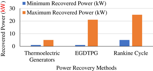
Several waste heat recovery (WHR) methods have been investigated to utilize the exhaust gases from internal combustion engines. Among these, Thermoelectric Generators (TEGs) and Rankine Cycle systems are common. TEGs are attractive due to their compact size and simplicity but typically generate only 1–5 kW of power, limiting their use in high-demand automotive systems [22]. Conversely, Rankine Cycle-based systems can recover 5–25 kW of power and offer higher efficiency but are often bulky and complex, making them challenging to integrate into compact vehicle designs [23]. Compared to these, an exhaust gas-driven turbine-powered generator (EGDTPG) offers a balanced solution, with a power output range of 1.03–21.04 kW while maintaining relatively simple integration and high adaptability across engine platforms [24]. This makes the EGDTPG an attractive choice for enhancing vehicle energy efficiency.
This study suggests a turbine-powered generator fuelled by exhaust gas as an alternative to traditional alternators in order to address these issues. This system reduces the mechanical workload on the engine and increases overall efficiency by capturing and using exhaust gas energy to optimize electricity generation for vehicle electrical systems. In order to assess the system's viability for real-world automotive applications, the study looks at how different engine speeds and exhaust gas pressures affect system performance. This present work is intended to help initiatives to improve fuel efficiency and sustainability in the automobile sector as well as advances in vehicle energy management by creating an alternative power production system.
2 Materials and Methods
A methodical approach was used to accomplish the goals of this research study, starting with a thorough analysis of the body of literature already written about the subject. The design of the current study was informed by the gaps in knowledge, theoretical frameworks, and approaches identified by this literature assessment. The creation of MATLAB/Simulink models to mimic the system under study was the following step after the literature review. During this phase, intricate models that faithfully captured the system's dynamics were created, enabling in-depth analysis and assessment. In order to make sure the models were reliable and able to produce significant findings, the design process involved specifying the simulation's parameters, input variables, and intended results. Following the modeling process, a number of simulations were run to examine how the system behaved in different scenarios. The findings were then critically examined and discussed in light of the original goals, emphasizing important discoveries and resolving any differences found with the body of existing literature. In the end, this thorough approach cleared the path for more research work and added insightful information to the subject of study.
2.1 Power Flow in EGDTPG
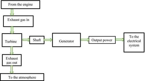
A block diagram that describes the energy conversion process can be used to show the power flow of the exhaust gas-driven turbine-powered generator. A turbine is powered by exhaust gases from an internal combustion engine, as seen in Figure 1. A generator transforms this mechanical energy into electrical energy, which can power the vehicle's electrical systems. In addition to providing power for the car's electrical systems, the electricity created lessens the strain on the engine, which increases fuel economy and lowers pollutants. In the end, this approach supports environmental sustainability and fuel conservation.
2.2 Power Requirements of Generator
Under all operating circumstances, the generator must be able to provide the vehicles' current needs. The generator side of the exhaust gas-driven turbine-powered generator was the first to undergo design examination. First, the generator's power needs were established before a turbine study was conducted. The energy required to run the car's electrical systems is represented by this power. Three groups—continuous loads, prolonged loads, and intermittent loads—were created using an inventory of the electrical components utilized in the automobile. The combined electrical load that these components require is roughly 2.07 kW. A 10% safety factor was included to account for design issues, which meant that the vehicle's electrical system would need about (2.07 + 2.07 × 0.1) = 2.27 kW of electricity from the generator. Furthermore, it is projected that 734 W of power are needed at idle speed. The overall power required for the vehicle's electrical systems was taken into account when establishing these two power restrictions.
2.3 Generator Parameters Determination
The generator parameters are crucial for determining its dimensions. These parameters are calculated using the following equations:
The output power of the generator can also be expressed in terms of current and voltage as follows.
2.4 Preliminary Analysis of Turbine Design
The EGDTPG system's turbine, which is powered by exhaust gas energy, is an essential part of the mechanical to electrical energy conversion process. The compact size, excellent efficiency at low mass flow rates, and suitability for automobile exhaust gas circumstances led to the selection of a radial inward-flow turbine. In order to properly size turbine blades, the preliminary turbine design process involved estimating the available exhaust gas power at each engine speed (700, 1500, 2000, 2800, and 3600 rpm), calculating exhaust gas velocity based on mean piston speed and exhaust pipe diameter by applying conservation of mass, and determining the volume flow rate and mass flow rate of exhaust gases at various engine speeds.
Furthermore, the turbine rotor's inducer and exducer dimensions were computed using particular mass flow rates and thermodynamic parameters. According to the design, exhaust gases enter the turbine radially and depart axially. The flow is thought to be isentropic, and there is very little heat loss throughout the turbine. In order to maximize energy extraction while minimizing exhaust backpressure, the turbine blade angles and dimensions were optimized. In the end, the turbine was sized to accommodate the generator's electrical load requirements while continuing to run effectively across the engine's operating speed range. In this section, a preliminary analysis was carried out prior to the design of the turbine and its related components.
2.5 Gas Velocity
The velocity of the exhaust gases in the exhaust pipe is determined using Figure 2.
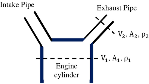
To determine the relevant parameters, the engine specifications of a specific vehicle model must be considered. The selection of a vehicle model is based on its integration of multiple electrical systems. For this study, the technical specifications of the vehicles are used, and these specifications are outlined in Table 1.
| Optimal drive 2.2-lite D-4D (Direct injection 4 cylinder common rail diesel engine) | |||
|---|---|---|---|
| Engine code | 2AD-FTV | ||
| Type | Four cylinders in-line | ||
| Valve mechanism | 16-valve, DOHC, chain drive | ||
| Bore × stroke (mm) | 86.0 × 96.0 | ||
| Displacement (cc) | 2231 | ||
| Compression ratio | 15.7: 1 | ||
| Max. power (bhp/kW @ rpm) | 148/110 @ 3600 | ||
| Max torque (Nm/rpm) | 340 @ 2000–2800 | ||
| Max. speed (mph)/Kmph | 118/190 | ||
| Gear Ratios | |||
| 1st | 3.818 | 5th | 0.809 |
| 2nd | 1.913 | 6th | 0.711 |
| 3rd | 1.218 | Reverse | 4.139 |
| 4th | 0.880 | Differential | 4.600 |
| Tire size | 235/55 R18 | ||
2.5.1 Gas Velocity Calculation
Since exhaust gas flow is linked to engine speed, it is determined using the specified engine speed of 3600 rpm, which corresponds to the maximum engine power. The mean piston speed is calculated as follows: it represents the average speed of the piston in a reciprocating engine and is essential for determining the exhaust gas velocity.
2.5.2 Exhaust Gas Pipe
The exhaust gas pipe is designed to allow the flow of exhaust gases. The diameter of the exhaust gas pipe is calculated using the following formula.
The area of exhaust gas pipe,
2.5.3 Volume Flow Rate of Exhaust Gas
Volume flow rate refers to the volume of exhaust gas that passes through a given area per unit time. It is determined after calculating the engine cylinder volume, which is calculated as follows.
The engine specifications are used to determine various parameters. This vehicle falls under the category of light-duty vehicles. For the analysis of the required parameters, an engine idle speed of 700 rpm, corresponding to this light-duty vehicle, is utilized.
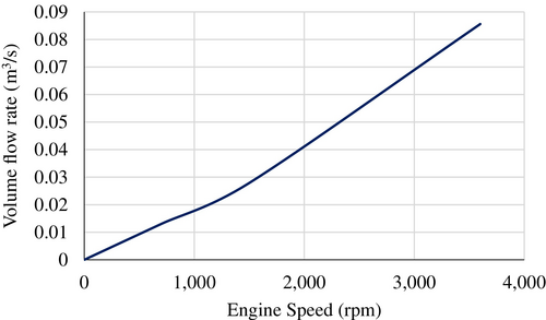
The graph in Figure 3 shows the relationship between the volume flow rate of exhaust gas and engine speed. Based on the graph's behavior, the volume flow rate of exhaust gas is directly proportional to engine speed.
2.6 Mass Flow Rate of Exhaust Gases
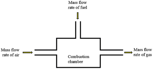
The mass flow rate of exhaust gas is analyzed using the principle of conservation of mass. The mass flow rate of gas exiting the combustion chamber is the sum of the mass flow rates of air and fuel entering the combustion chamber. It is calculated using Figure 4.
2.7 Mass Flow Rate of Air
The mass flow rate of air is the amount of air entering the internal combustion engine per unit of time, and it depends on the engine's volumetric efficiency. It is determined as follows.
The volumetric efficiency (ηv) for a turbocharged engine is typically around 110%. This high efficiency occurs because turbocharging increases the amount of air entering the combustion chamber, allowing the engine to take in more air than its displacement volume, thus exceeding 100% efficiency.
2.7.1 Mass Flow Rate of Fuel
The mass flow rate of fuel refers to the rate at which fuel is injected into the combustion chamber. It is calculated as follows.
Since the air-fuel ratio is unknown, its stoichiometric value is calculated as follows. The engine specified is a diesel engine, and the common chemical formula for diesel fuel is .
2.8 Exhaust Back Pressure
Exhaust backpressure in an internal combustion engine is the pressure created by the engine to overcome the resistance of the exhaust system, allowing the gases to be discharged into the atmosphere. In other words, it is the resistance encountered by exhaust gases as they exit the combustion chamber during the exhaust stroke, flow through the exhaust pipe, and are expelled into the atmosphere.
At 1500 rpm, = 0.23 kPa, At 700 rpm, = 0.104 kPa
The maximum recommended exhaust backpressure is approximately 20 kPa for engine power levels ranging from 50 to 500 kW. Since the pressure of the exhaust gas is higher than atmospheric pressure, it does not significantly contribute to the formation of backpressure.
2.9 EGDTPG With Turbocharger
The new system, illustrated in Figure 5, operates downstream of the turbocharger. As shown, fresh air enters the compressor, which then forces the air into the engine. The engine expels the burned exhaust gases, which first drive the turbocharger turbine and subsequently flow to the generator turbine. After powering the generator turbine, the exhaust gases are released into the environment.
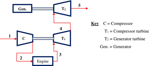
2.10 Compressor
The compressor is a key component of the turbocharger that compresses fresh air before it enters the engine. It operates through isentropic compression.
2.10.1 Process 1–2 Isentropic Compression
Matching routine: The matching routine is crucial for maintaining the optimal relationship between the turbine and compressor in a gas system. Proper alignment of components that influence the mass flow of gas is essential for achieving smooth and efficient operation of the entire system. This process involves ensuring that the characteristics of the turbine and compressor are compatible, thereby facilitating seamless energy transfer and minimizing potential operational disruptions. At point 1, where the incoming air enters the compressor, the atmospheric pressure is 101,325 Pa, while the ambient temperature is 298.15 K. These parameters are critical as they affect the performance and efficiency of the compressor, influencing the overall effectiveness of the system.
The temperature and compressor efficiency () are determined as follows.
The temperature at point 2, = 387 .
The mass flow rate of air, = 0.1327 kg/s.
The corrected mass flow rate, = 0.07674 kg/s = 12.17 Ib/min.
By plotting and on the compressor map, the compressor efficiency, = 72%.
2.10.1.1 Process 2–3 (IC Engine)
The standard intake air temperature is approximately 50°C. The process involves calculating the temperatures and pressures at various points. These parameters are crucial for determining the amount of exhaust gas energy flowing through the generator turbine. The required parameters are calculated using the following mathematical equations.
Mass flow rate of exhaust, =
Of the heat supplied to the combustion chamber, approximately 33% is transferred to the coolant. Another one-third of the energy is exhaust gas energy, which comprises heat energy, flow energy, internal energy, kinetic energy, and potential energy. Kinetic and potential energies are typically neglected due to their relatively small values compared to the flow and heat energies of the gases.
Now the exhaust gas energy at engine speed of 3600 rpm,
2.11 Exhaust Gas Power Calculation
On the left side of the graph, the line indicates a gradual increase in exhaust gas power as the engine speed rises from 700 to 1500 RPM. This trend demonstrates the engine transitioning from an idling condition to a driving condition. Beyond this range, the line shows a rapid increase in exhaust gas power corresponding to the engine speed on the right side of the graph, indicating the engine speed is moving from medium to maximum levels is shown in Figure 6.
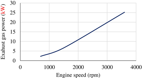
2.11.1 Compressor Turbine (Process 3–4)
The temperature at point 4 is calculated using the following formula.
2.11.2 Generator Turbine (Process 4–5)
2.12 EGDTPG Without Turbocharger
The 2D modeling of the exhaust gas-driven turbine-powered generator system, without a turbocharger, is illustrated in Figure 7. The fresh air enters the engine, which subsequently releases exhaust gas directed toward the generator turbine. The exhaust gas drives the turbine, which then expels the gases into the external environment.
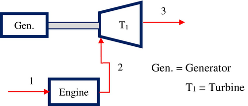
The volumetric efficiency of a naturally aspirated engine is lower than that of a turbocharged engine. As shown in Table 2 the flow rate of gases as well as gas velocity increases with increased engine speed.
| Engine speed (rpm) | Mass flow rate of gas (kg/s) | Volume flow rate of gas | Gas velocity (m/s) |
|---|---|---|---|
| 3600 | 0.0863 | 0.06694 | 89.85 |
| 2800 | 0.06688 | 0.05206 | 69.88 |
| 2000 | 0.04749 | 0.03719 | 49.92 |
| 1500 | 0.03532 | 0.02789 | 37.44 |
| 700 | 0.016664 | 0.01302 | 17.48 |
2.12.1 Process 1–2 (Between Intake Manifold and Turbine)
The process involves calculating the unknown parameters, which are essential for determining the amount of exhaust gas energy flowing through the turbine. The required parameters are derived using the following mathematical equations.
2.12.2 Turbine (Process 2–3)
The temperature at exit of turbine,
2.12.3 Exhaust Gas Power Calculation
The exhaust gas power at engine speed of 3600 rpm,
The exhaust gas power at engine speeds of 1500 and 700 rpm is:
2.13 Turbine Design
The turbine is a component of the EGDTPG that converts the energy of exhaust gases into rotational energy. This rotational energy is then used by the generator to produce electricity. As discussed in the literature review, the radial flow turbine, specifically the inward flow radial turbine, is well suited for exhaust gas-driven turbine-powered generators. This system has a lower mass flow rate of gas compared to the mass flow rates found in aircraft and industrial axial turbines. The inward flow radial (IFR) turbine can be classified into two types: the cantilever IFR turbine and the 900 IFR turbine. The 90° IFR turbine is preferred over the cantilever IFR turbine due to its higher structural strength. Overall, the 90° IFR turbine is selected for the design of the EGDTPG.
2.13.1 Design Analysis of Turbine
The overall dimensions of the exhaust gas-driven turbocharged power generator (EGDTPG) are specified as illustrated in Figure 8. The length (l) and height (h) are used to define these dimensions. The cross-sectional area and the radius from the turbine centerline to the centroid of that area are depicted on the turbine housing in Figure 8. Additionally, the dimensions of the inducer (exhaust gas inflow) and exducer (exhaust gas outflow) of the turbine rotor are shown in Figure 9.
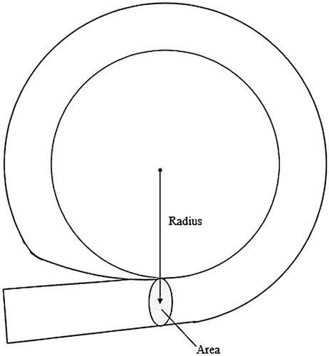
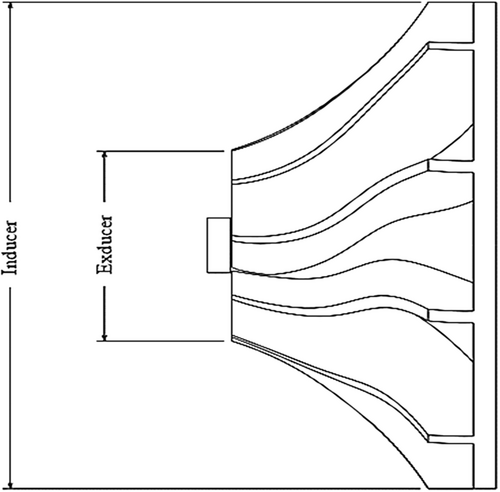
According to the specifications from the Holst turbocharger guide, for engine displacements ranging from 1.7 to 2.5 L and horsepower between 150 and 260, the cross-sectional area to radius from the turbine centerline to the centroid of that area (A/R) is 0.67, and the trim is 72.
Trim is a ratio used to describe the turbine wheel dimensions that are based on the inducer and exducer diameters of the turbine.
The diameter of the inducer can be estimated using the diameter of the exhaust pipe. According to Birmingham Wire Gauge (BWG) standards, the thickness of the exhaust pipe is approximately 0.56 mm. The exhaust pipe surrounds the turbine, and the inducer diameter is determined as follows.
The exducer diameter is calculated based on the inducer diameter using the formula provided above. The calculation is performed as follows.
A velocity triangle is formed by three different velocities involved in the turbine and gas movement. The nomenclature and velocity triangles are illustrated in Figure 10.
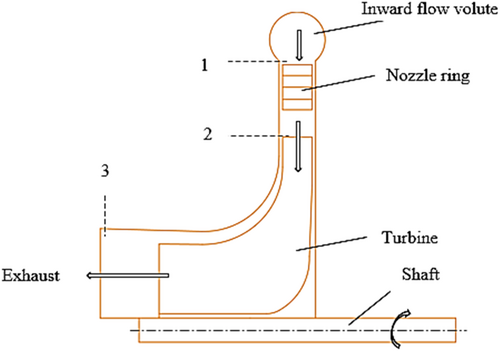
The velocity triangle is constructed based on Figures 11 and 12. The various velocities and associated parameters are determined using the velocity triangle.
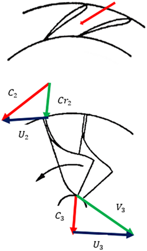
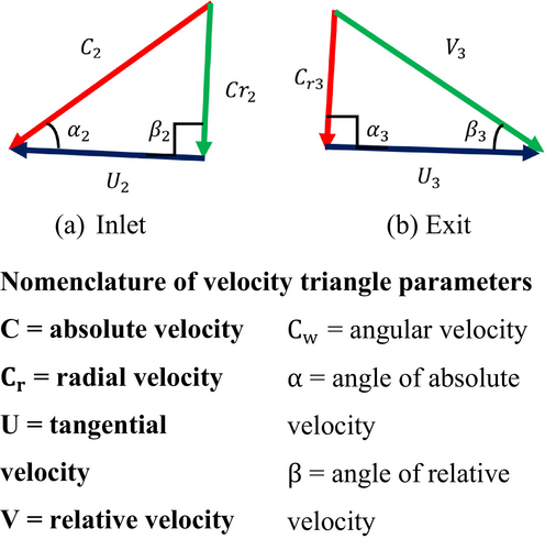
Since the inlet angle of the relative velocity () is 90°, the inlet radial and tangential velocities are equal to the inlet relative and angular velocities, respectively. Similarly, the exit radial and tangential velocities are equal to the exit absolute and angular velocities, as the exit angle of the absolute velocity is also 90°. The parameters at various stages are calculated as follows.
Using the steady flow energy equation, the absolute velocity at the inlet of the turbine is calculated as follows.
For isentropic process,
The number of blades should be determined to prevent reversed flow on the pressure side. It is calculated using the following equation.
2.14 Design of Gearbox
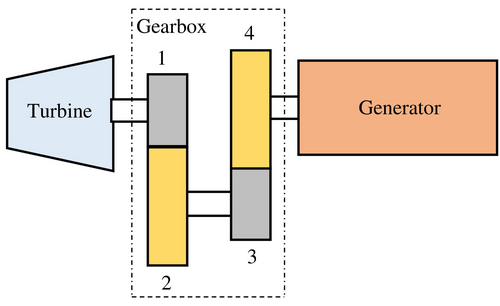
The speed of the generator is significantly lower than that of the turbine. To align the turbine speed with the generator speed, a gearbox is required to reduce the turbine's rotational speed. This reduction is essential to ensure that the turbine operates in harmony with the generator, facilitating smooth and efficient operation of the entire system. By using a gearbox, it is possible to achieve the necessary speed adjustments, which helps optimize performance and prolong the lifespan of both the turbine and the generator, as shown in Figure 13.
2.15 Design of Shaft
A shaft is a rotating machine element used to transmit power from one location to another. It transfers power from the exhaust gas-driven turbine to the generator for the production of electric power in electrical systems. When the system begins to operate, the shaft experiences a twisting moment as it facilitates power transfer. The diameter of the shaft is determined using the torsion equation. The power transmitted by shaft,
The diameter of the shaft can be determined using the two torque relations: T = and as follows. The diameter of shaft,
3 Results and Discussion
The EGDTPG system was modeled and simulated using MATLAB/Simulink to evaluate performance under various operational conditions. A three-phase Y-connected generator model was developed to enable high voltage generation at lower rotational speeds, and the turbine mechanical output was modeled based on calculated mass flow rates and exhaust gas energy. A shaft model was incorporated to link the turbine and generator, considering minor mechanical losses, while a gearbox model was included to match the turbine's high rotational speed to the generator's optimal speed. For the simulations, input parameters such as engine speeds (700, 1500, 2000, 2800, and 3600 rpm), corresponding exhaust gas mass flow rates and velocities, and turbine torque outputs derived from available exhaust gas power were considered. For each engine speed, exhaust gas conditions were fed into the turbine model, and the resulting turbine torque was transmitted to the generator via the shaft and gearbox. Generator outputs including voltage, current, and power were recorded, and separate simulations were conducted for both naturally aspirated and turbocharged engine configurations. The simulation results indicated that electrical output increased with engine speed. Naturally aspirated engines provided higher exhaust energy for the turbine, resulting in greater generator outputs compared to turbocharged engines. A maximum generator output of 21.04 kW was achieved with the naturally aspirated configuration at 3600 rpm.
3.1 Modeling and Simulation Using MATLAB/Simulink
The generator model illustrated in Figure 14 has been developed using the blocks from the Simulink library in MATLAB. These blocks are interconnected to create a comprehensive model of the generator.
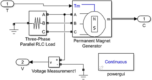
The three generator parameter values—voltage, frequency, and power are—entered by selecting the three-phase parallel RLC load, as depicted in Figure 15.
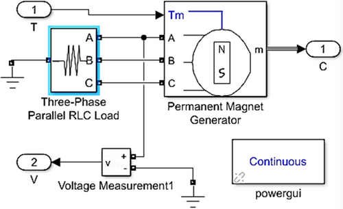
The number of phases, rotor type, and mechanical input are determined in Figure 16 by selecting the permanent magnet generator block.
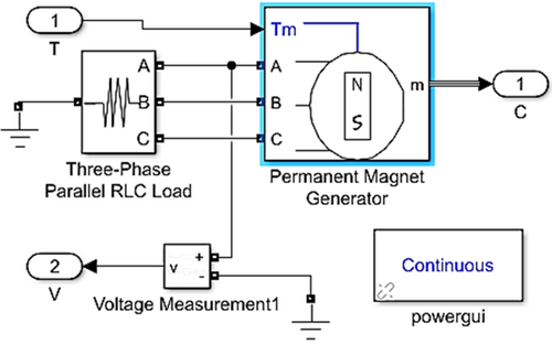
The modeling and simulation of the exhaust gas-driven turbine-powered generator system have been conducted using MATLAB/Simulink, allowing for a thorough comparison of the simulation results with the calculated outcomes. In this setup, the system model is constructed by integrating the turbine with a gearbox and a generator, as illustrated in Figure 17. This configuration enables the examination of the interactions between the components, ensuring a comprehensive understanding of their performance dynamics. Once the modeling has been completed, the system undergoes simulation to generate graphical representations of the desired parameters, providing valuable insights into the operational characteristics and efficiency of the exhaust gas-driven turbine-powered generator and facilitating analysis and optimization of the system.

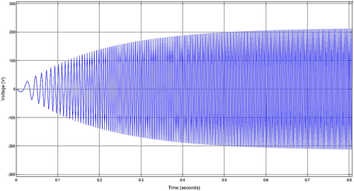
The sinusoidal waveform of the voltage, depicted in Figure 18, reaches its peak value and maintains this level as the engine operates. This sustained maximum voltage indicates a consistent power output generated by the system during its functioning. As the engine runs, the voltage fluctuations remain within the established limits, demonstrating the stability of the electrical output. This behavior is crucial for ensuring that the connected electrical systems can operate efficiently without experiencing voltage spikes or drops, which could affect performance and reliability.

As illustrated in Figure 19, it takes approximately 0.8 s for the system to reach its maximum value. This duration signifies that, during this initial 0.8 s, all electrical systems will remain non-operational. This delay could impact system performance and efficiency, as it prevents any electrical operations from occurring until the maximum value is achieved. Understanding this lag is crucial for optimizing the system's response and ensuring that all components are synchronized for optimal functionality.
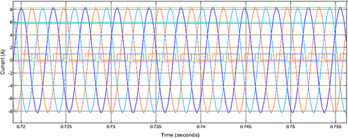
The output current waveform, illustrated in Figure 20, achieves its peak value during the electricity production phase, which corresponds to the operational conditions of the engine. This maximum current output signifies that the generator is effectively converting mechanical energy into electrical energy, ensuring optimal performance of the system. As the engine operates under various driving conditions, the waveform reflects the dynamic nature of current generation, capturing the fluctuations associated with different loads and demands. The consistency in reaching this maximum value is essential for maintaining a reliable power supply, indicating that the generator can meet the energy requirements of vehicle electrical systems without compromising performance.
Similar to Figure 21, the output current waveform takes approximately 0.8 s to reach its maximum value. This delay in achieving peak current indicates that the system requires this initial period before full operational capacity is attained. Understanding this response time is essential for effective system performance analysis and for ensuring that all electrical components function harmoniously.
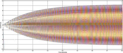
The results indicate that the current and voltage values obtained were a little bit lower than the numerical values calculated in the analysis section. This discrepancy can be attributed to certain parameters present in the Simulink models that were not accounted for in the analytical calculations. These parameters may include specific system losses, component efficiencies, or environmental factors that influence performance but were excluded from the initial analysis. Consequently, this highlights the importance of integrating comprehensive system characteristics into both modeling and analysis to ensure a more accurate representation of the generator's operational performance. Understanding these differences is useful for refining models and enhancing the reliability of predictions in future simulations.
3.2 Numerical Result Analysis
The performance of the exhaust gas-driven turbine-powered generator is investigated through a numerical study that considers various parameters, including engine speed, exhaust gas power, volumetric flow rate of the exhaust gas, and overall system efficiency. The engine speed is categorized into distinct ranges: 700 rpm representing low speed, 1500, 2000, and 2800 rpm representing medium speeds, and 3600 rpm representing high speed. This study meticulously examines how variations in engine speed impact these critical performance parameters. By analyzing the relationship between engine speed and performance metrics, valuable insights can be gained regarding the efficiency and effectiveness of the generator system across different operational conditions. This analysis not only enhances our understanding of the system's behavior but also provides a foundation for optimizing design and operational strategies in exhaust gas-driven turbine systems.
A comparison of EGDTPG system with previous studies reveals notable improvements. For instance, Gürbüz et al. demonstrated that a latent heat thermal energy storage system for exhaust gases in SI engines recovered approximately 8.5% of the waste heat energy [22]. Similarly, Gürbüz et al. (2022, J. Energy Storage) reported that integrating a phase change material system achieved approximately 9% energy recovery efficiency [23]. In our study, the exhaust gas-driven turbine-powered generator achieved a system efficiency of up to 66.8% for naturally aspirated engines (Table 3), representing a significant improvement compared to the 8%–9% reported in the previous studies. Furthermore, Gürbüz et al. highlighted an integrated TEG-thermal energy storage system that reached around 10% recovery efficiency [24], while the EGDTPG system demonstrated higher efficiency. Additionally, Gürbüz et al. (2022, Applied Thermal Engineering) developed a TEG system that achieved a maximum recovery efficiency of approximately 12% [25], while our system again surpassed this by approximately 54%.
| Engine speed (rpm) | Output power (kW) | System efficiency (%) | ||
|---|---|---|---|---|
| Turbocharged | Naturally aspirated | Turbocharged | Naturally aspirated | |
| 3600 | 12.12 | 21.04 | 48.1 | 66.8 |
| 2800 | 8.44 | 13.7 | 46.4 | 61.7 |
| 2000 | 4.95 | 7.3 | 44.67 | 56.6 |
| 1500 | 2.9 | 3.78 | 43.6 | 53.4 |
| 700 | 0.6 | 1.03 | 26.8 | 41.86 |
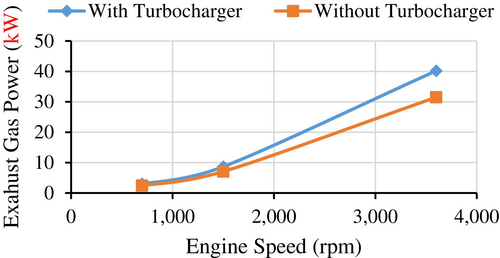
3.3 Influence of Engine Speed on Exhaust Gas Power Before Turbocharger
The Figure 22 provides a graphical representation of the exhaust gas power generated by turbocharged and naturally aspirated engines. The exhaust gas power of a turbocharged engine is significantly higher than that of the naturally aspirated engine. This increase in power can be attributed to the superior volumetric efficiency of the turbocharged engine, which results from compressed air being forced into the combustion chamber. This enhanced airflow allows for a more efficient combustion process, leading to greater power output.
3.4 Influence of Engine Speed on Exhaust Gas Power After Turbocharger
The influence of engine speed on exhaust gas power is illustrated in Figure 23, which provides a graphical comparison for both turbocharged and naturally aspirated engines. As shown in Figure 23, the exhaust gas power produced by naturally aspirated engines is greater than that generated by turbocharged engines. This phenomenon can be attributed to the power consumption associated with the turbocharger in turbocharged engines. The turbocharger requires a portion of the engine's output power to function effectively, leading to a reduction in the available exhaust gas power. Consequently, while turbocharged engines are designed to enhance overall performance and efficiency, the inherent energy demands of the turbocharger result in lower exhaust gas power compared to their naturally aspirated counterparts.
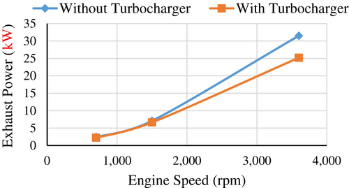
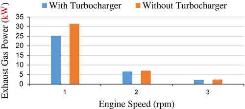
Figure 24 illustrates exhaust gas power using a bar chart, highlighting the peak power at three different engine speeds for both naturally aspirated and turbocharged engines. This visual representation allows for easy comparison of the power output between the two engine types across the specified speeds.
3.5 Influence of Engine Speed on System Efficiency
The influence of engine speed on system efficiency is depicted in Figure 25, which presents the graphical characteristics of system efficiency across various engine speeds. System efficiency is defined as the combined efficiency of the turbine, gearbox, and generator, reflecting the overall effectiveness of the power generation process. As illustrated in Figure 25, system efficiencies for both turbocharged and naturally aspirated engines tend to improve as engine speed increases. However, it is noteworthy that the system efficiency of turbocharged engines remains lower than that of naturally aspirated engines. This difference arises because the exhaust gas power reaching the turbine in naturally aspirated engines is greater than that in turbocharged engines. The turbocharger's operational demands consume some of the available exhaust gas power, thereby reducing the power available for the generator turbine.

The output power of the generator and system efficiency for both engine types are presented in Table 3. As shown in Table 3, both output power and system efficiency decrease with lower engine speeds for each engine type. Notably, the values for naturally aspirated engines in both parameters (output power and system efficiency) are higher than those for turbocharged engines. This difference can be attributed to the exhaust gas power consumed by the turbocharger, as previously explained.
3.6 Influence of Engine Speed on Current
The graph of current versus engine speed presented in Figure 26 features two lines representing naturally aspirated and turbocharged engines. The production of current increases with engine speed for both types of engines. Notably, the output current generated by the naturally aspirated engine is higher than that of the turbocharged engine. This difference can be attributed to the turbocharger, which utilizes a portion of the exhaust gas power in turbocharged engines. Consequently, this consumption reduces the overall output current of the generator in turbocharged systems.

3.7 Influence of Engine Speed on Output Power
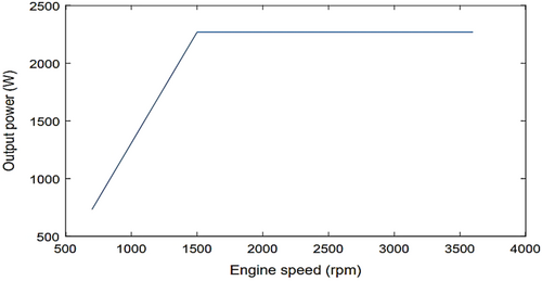
The influence of engine speed on output power is illustrated graphically in Figure 27, which shows the generator's output power at various engine speeds. The output power increases as engine speed rises, reaching a peak at medium speeds during driving conditions. Once this maximum required value is attained, the output power remains constant, even as the engine speed continues to increase beyond the medium range. This behavior is attributed to the vehicle's electrical system requirements, which dictate that the output power reaches a maximum value necessary to meet the system's demands.
3.8 Graphical Behavior of Output Power With System Efficiency
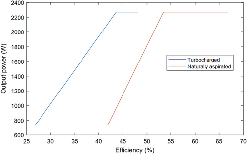
The graph of output power versus system efficiency, shown in Figure 28, demonstrates that system efficiency increases with the generator's output power until it reaches a constant level. This plateau indicates that the power required by the electrical systems during driving, from the lowest to the maximum engine speed, remains constant throughout operation.
3.9 Overall Analysis of EGDTPG With Turbocharger and Without Turbocharger
The parameters, including exhaust gas power, volumetric flow rate of exhaust gas, turbine efficiency, and others, are presented in Tables 4 and 5. These tables summarize the numerical results of the exhaust gas-driven turbine-powered generator for vehicles equipped with both turbocharged and naturally aspirated engines.
| Engine Speed (rpm) | Volume flow rate of gas (m3/s) | Mass flow rate of gas (kg/s) | Exhaust pressure (kPa) | Engine Speed (rpm) | Volume flow rate of gas (m3/s) |
|---|---|---|---|---|---|
| 3600 | 0.06694 | 0.09323 | 294.32 | 25.2 | 52.4 |
| 2800 | 0.05206 | 0.07251 | 272.76 | 18.18 | 50.53 |
| 2000 | 0.03719 | 0.04847 | 251.2 | 11.09 | 48.7 |
| 1500 | 0.02789 | 0.038850 | 237.72 | 6.63 | 47.5 |
| 700 | 0.01302 | 0.018133 | 171.27 | 2.23 | 29.2 |
| Engine speed (rpm) | Volume flow rate of gas (m3/s) | Mass flow rate of gas (kg/s) | Exhaust pressure (kPa) | Engine speed (rpm) | Volume flow rate of gas (m3/s) |
|---|---|---|---|---|---|
| 3600 | 0.06694 | 0.084755 | 391.1 | 31.5 | 72.8 |
| 2800 | 0.05206 | 0.06688 | 338.76 | 22.2 | 67.2 |
| 2000 | 0.03719 | 0.04749 | 286.41 | 12.89 | 61.63 |
| 1500 | 0.02789 | 0.03532 | 253.7 | 7.07 | 58.14 |
| 700 | 0.01302 | 0.01666 | 188.1 | 2.45 | 45.61 |
Table 4 presents various parameters of the exhaust gas-driven turbine-powered generator (EGDTPG) for turbocharged engines at different engine speeds. It is evident that the values of all parameters decrease as engine speeds decline. Due to the presence of the turbocharger, the parameters for turbocharged engines, such as exhaust gas pressure, exhaust gas power, and turbine efficiency, are lower than those of naturally aspirated engines. This reduction can be attributed to the decrease in exhaust gas energy, which is consumed by the turbocharger during operation. However, the mass flow rates of exhaust gas for turbocharged engines are higher than those for naturally aspirated engines, as the turbocharger effectively boosts more air into the combustion chamber.
Table 5 presents various parameters of the EGDTPG for naturally aspirated engines (without a turbocharger) at different engine speeds. The values of these parameters increase with higher engine speeds, indicating improved performance under these conditions. However, it is important to note that the mass flow rates of exhaust gas for naturally aspirated engines are lower than those for turbocharged engines. This difference is primarily due to the lack of a turbocharger, which in turbocharged engines enhances the intake of air into the combustion chamber, resulting in greater exhaust gas flow.
3.10 Comparison of Power Recovery Methods
The Figure 29 illustrates the comparison of EGDTPG with TEG and the Rankine Cycle, highlighting these differences in power recovery capabilities visually. The comparison of power recovery methods in internal combustion engines reveals significant differences in efficiency. The Rankine Cycle, with a minimum power recovery of 5 kW and a maximum of 25 kW, shows remarkable potential for harnessing waste heat from exhaust gases, surpassing both TEGs and Exhaust Gas Driven Turbine-Powered Generators (EGDTPGs) in terms of power output. However, its implementation in vehicles faces significant challenges, such as complexity, weight, and space requirements. The need for large heat exchangers and additional components can complicate integration into compact automotive designs, making it less feasible for lightweight vehicles or those with stringent space constraints. In contrast, while TEGs recover less power (1–5 kW), their compactness and simplicity make them more suitable for smaller vehicles, and EGDTPGs offer a good balance with a recovery range of 1.03–21.04 kW. Thus, while the Rankine Cycle holds great promise for large-scale waste heat recovery, its practical limitations often hinder widespread adoption in the automotive sector.
4 Conclusion
- The output electric power of the EGDTPG is primarily influenced by exhaust gas pressure rather than by the mass flow rate or volumetric flow rate of exhaust gas.
- Installing the EGDTPG on naturally aspirated engines proves to be more effective than on turbocharged engines.
- The output electric power of the generator ranges from 0.6 to 12.12 kW for turbocharged engines and from 1.03 to 21.04 kW for naturally aspirated engines.
- Turbine, generator, and system efficiencies have been calculated and compared between turbocharged and naturally aspirated engines at idle, medium, and maximum engine speeds, revealing that the efficiencies of naturally aspirated engines are consistently higher than those of turbocharged engines.
- The system efficiency for naturally aspirated engines at idle speed, medium speeds, and maximum engine speed is observed in the following order: 41.8%, 53.4%, 56.6%, 61.7%, and 66.8%, respectively. In contrast, the system efficiencies for turbocharged engines are 26.8%, 43.6%, 44.67%, 46.4%, and 48.1%, respectively.
Conflicts of Interest
The authors declare no conflicts of interest.
Open Research
Data Availability Statement
All data collected are provided in this manuscript.


