Optimized Control of Hybrid Energy Storage Systems Using Whale Optimization Algorithm for Enhanced Battery Longevity and Stability in Microgrids
ABSTRACT
The target of achieving net-zero emissions by 2050 requires integrating a significant share of renewable energy. However, this integration can cause instability in microgrid operations. Hybrid energy storage systems (HESS), consisting of battery energy storage systems (BESS) and supercapacitors, address these challenges but necessitate complex control strategies. Traditional frequency-based methods (FBM) enhance HESS performance but do not guarantee continuous operation and may lead to BESS degradation. This article proposes an optimized FBM control approach using the whale optimization algorithm (WOA) to improve HESS operation. The method optimizes two key variables: current sharing coefficients and the smoothing constant, enabling continuous HESS functionality. The proposed FBM-WOA reduces high-frequency current stress on BESS, minimizes BESS usage, and ensures supercapacitor state-of-charge levels remain within safe limits. The proposed approach achieves the lowest BESS life loss and voltage fluctuations in both test load and microgrid load cases. It decreases BESS life loss by 11.59% and 0.25% compared to rule-based (FB-RB) and current sharing coefficient (FB-COEFF) methods, respectively, for test load cases. Similarly, it reduces average BESS life loss by 1.45% and 2.35% compared to FB-RB and FB-COEFF methods for real load cases over five different days.
1 Introduction
To achieve the net-zero goal of the United Nations Framework Convention on Climate Change, we need to shift towards the cleaner electricity solutions provided by renewable energy sources (RES). The shares of wind energy required to achieve this target in “Green,” “Gray,” and “Red” scenarios of the Neo Outlook Report 2021 are 52%, 40%, and 27%, and that of solar energy is 32%, 22%, and 12%, respectively. This means that at least 39% RES share is needed to reach the net-zero emissions target by 2050. A growth in RES, on the other hand, may cause several issues, including inferior electrical networks, instability, and intermittency [1-5]. As a result of these issues, many network operators have imposed conditions that must be addressed to integrate the RES. One of the network operator's key concerns is the ramp rate of generation, which is particularly unpredictable and prone to violation in microgrids (MG) with RES installed [3, 6]. In addition to ramp rate concerns, RES makes inter-link bus parameters exceedingly unstable, necessitating rigorous control to keep these parameters within safe and stable bounds.
1.1 Literature Review
Energy storage is necessary for the integration of increasing shares of the RES on utility scale [7]. These energy storage systems include flywheel energy storage, supercapacitors (SC), pumped hydro storage, and battery energy storage systems (BESS). These energy storages have different energy storage principles and consequently have unique characteristics which make them suitable for different applications. Therefore, the complementary strengths of these energy storage systems can be used together in hybrid combinations. These systems are then referred to as hybrid energy storage systems (HESS) which are increasingly being adopted due to their capacity to compensate for both high and low-frequency power imbalances produced by RES systems [8-11]. Some of the HESS are made using BESS of different types to save costs and get the benefits of using different technologies together. However, the BESS alone cannot deal with the high frequency power imbalances and fast load changes due to low power density [8]. The most typical HESS components are BESS in combination with SC because it is a reliable source of high power that can withstand power peaks [12].
Control techniques are then employed to improve the performance and lifespan of HESS components. Several current allocation techniques are being used for HESS. Frequency-based methods (FBM) are some of the most often used current allocation strategies [8, 13-15]. In these techniques, the current allocation is done using the low-pass or high-pass filters. The HESS reference current is divided into low-frequency and high-frequency components. The low-frequency component is allocated to the BESS, whereas the high-frequency component is assigned to the SC. However, since the SC is a low energy density component, it can be charged/discharged quickly due to a small charge time. In conventional FBM current allocation, the SC is cut off to ensure that SoC remains within a predefined range. This is done using a set of rules and is referred to as rule-based FBM, and it is quite effective in current allocation based on high power and high energy components. However, it suffers from poor SoC regulation and coordination of HESS components because it cannot recover the SC SoC level. The rule-based FBM is the simplest and most effective strategy, but it causes HESS to run in discontinuous mode, where HESS components are cut off after reaching SoC limits [8]. This results in the allocation of high-frequency currents to BESS, leading it to degrade prematurely. In Reference [8], the author also shows that the continuous operation of HESS allows the PI controller of DC bus voltage to operate at higher gain values and can tolerate higher communication delays, essentially making the MG more marginally stable. Another technique is the power-sharing coefficient FBM approach, which helps in recovering SC SoC, but BESS utilization is increased and continuous operation is still not guaranteed. Another approach, namely adaptive frequency FBM, serves to smooth out the BESS current allocation, which reduces BESS degradation owing to high-frequency currents while increasing overall BESS consumption. Furthermore, such an approach also lacks sufficient SoC recovery features and can make the system unstable. Similarly, a HESS system can allocate current via time-varying cut-off frequency (TVF) management. Adaptive time constant LPF current allocation is used in Reference [16]. However, these methods either lack SoC recovery or overburden the BESS, and hence a trade-off is necessary.
Similarly, there are other techniques that are being used in literature for the smooth integration and stable operation of MG with RES. For example, the main concept of the study article in Reference [17] is to use superconducting magnetic energy storage (SMES) whenever a disturbance occurs and to maintain battery backup power until SMES's energy is almost depleted. The high-power component of HESS operates intermittently and hence its exhaustion reduces the system's dynamic stability due to a switch between continuous and discontinuous operating mode. In Reference [18], a single objective function based on change in battery power is utilized to manage the ramp rate of the grid power in order to limit power fluctuations. In Reference [13], the benefits and drawbacks of several FBM current allocation strategies are examined in relation to the deterioration of battery life. In Reference [19], the RB-FBM technique is used for the allocation of power between SC and BESS. In References [4, 20] meta-heuristic optimization techniques have been used for solving the energy management problems of MG. Energy management of HESS is also used in traction applications such as electric trains and EVs as well. The principle of this energy management is similar to that of MGs. For example, in Reference [21] the power demand from train speed demand is passed through a moving average filter to assign high frequency power to capacitors and low frequency demand to the BESS. In conclusion, some of these approaches offer advantages in terms of controllability, while others have advantages in terms of BESS life extension. However, there is no thorough research on the degradation effects of discontinuous operation of HESS on the BESS life. As a result, optimal control of the FBM current allocation technique is required to achieve the trade-off between SoC control and BESS utilization.
Model prediction control (MPC) is another widely used technique which is often used in tandem with FBM. The predictive model of the MG system is developed, and the sequence of control actions is computed over the prediction horizon using optimization [8, 10, 22]. In Reference [10], a two-stage MPC control technique divides the power variations into low-frequency and high-frequency bands in order to efficiently counteract the fluctuations of a wind power farm. Likewise, two-staged hierarchical control of the power ramp rate based on MPC is carried out in Reference [17]. In order to keep the ramp rate within a given range, the necessary HESS power is first determined. Following that, the estimated HESS power is allocated based on frequency, and SoC control is carried out. Similarly, in Reference [23], an MPC-based energy management system for MG is discussed. MPC is employed in References [10, 24] as well to accomplish smoother integration depending on various time frames. However, the impacts of discontinuous operation on BESS degradation and the assurance of continuous HESS operation are not investigated in these studies.
1.2 Research Contributions
In order to address the research limitations noted above, this work proposes FBM optimized control utilizing the whale optimization algorithm (WOA). There is no significant research in the literature on the degradation effects of high current changes and over-utilization of BESS during HESS discontinuous operations and ways to mitigate these abrupt changes. Similarly, combining different methods to utilize their benefits in a single hybrid technique specially to prolong BESS life has not been studied. The proposed FBM-WOA method searches for the optimum current allocation solution in the vicinity of the search space using the manipulated variables in order to mitigate the abrupt changes and to ensure continuous operation of the HESS so that the BESS life can be improved. Varying filter frequency and current sharing co-efficient are used as manipulated variables (searching whales) to operate the HESS in continuous mode thereby boosting controllability and decreasing the allocation of high-frequency currents to BESS as well as its overall usage. The research gap in the literature has been summarized in Table 1. The proposed FBM-WOA current sharing technique for HESS combines and manipulates the strengths of two presently available FBM techniques to achieve better results in terms of voltage profile and BESS life preservation.
| Research ref. no. | Publish year | Algorithm/ technique | Contribution | Limitations/research gap |
|---|---|---|---|---|
| [8] | 2022 | MPC | Focused on small signal stability improvement through continuous HESS operation using current sharing co-efficient in MPC strategy. | Only one manipulated variable (MV) is used for the current allocation control and saturation of such MV can lead to discontinuous operation. Multiple MVs can help overcome this problem. |
| [16] | 2023 | Adaptive Time-constant LPF | Adaptive time-constant LPF based current allocation technique has been proposed to counter the conventional energy management degrading effects on battery life. |
Adaptive time-constant LPF on its own cannot recover the SoC levels of HESS components and hence the discontinuous operation of the HESS cannot be avoided for large power fluctuations. Adaptive time constant LPF in tandem with current sharing coefficient can help find optimized solution utilizing benefits of both techniques. |
| [17] | 2021 | Single step direct voltage MPC for SMES control. | Proposes MPC-based voltage control and power allocation for enhancing MGs resilience. Utilizes hybrid energy storage system to counteract power fluctuations. Demonstrates fast response ability without causing DC bus voltage oscillation. | The main concept of the study is to use superconducting magnetic energy storage (SMES) whenever a disturbance occurs and to maintain battery backup power until SMES's energy is almost depleted. The high-power component of HESS operates intermittently and hence its exhaustion reduces the system's dynamic stability due to a switch between continuous and discontinuous operating mode |
| [22] | 2022 | Two-level MPC | Two-level model predictive control for building energy management with PV. Local controller manages building loads, energy storage, and PV generation. | The effects of high frequency currents and overuse of BESS imposed during discontinuous operation on BESS life have not been studied. |
| [13] | 2022 | FBM Based RB, COEFF, TVF and Loop Control | Comparative study on different filtration-based control of HESS system has been carried out. The study states that BESS degradation occurs in existing rule-based, current sharing coefficient based and loop control-based techniques. | The BESS life has not been calculated and exact effects on the BESS life have not been calculated. There is no proposed technique suggested for reducing the BESS degradation. |
- The proposed technique combines two classical methods, namely current-sharing coefficients and time-varying operating frequency methods, by integrating them using the Whale Optimization Algorithm (WOA).
- Discontinuous operations are avoided by smoothing transitions during state-of-charge (SoC) recovery. This is achieved by softening the SoC limit constraints through increased penalties in the cost functions.
- A BESS life loss model is developed to evaluate BESS degradation and compare the proposed FBM-WOA methodology with existing techniques in the literature.
- The study addresses the effects of abrupt BESS current changes, which contribute to its degradation. It focuses on smoothing BESS current transitions when the SoC limits of HESS components are approached, thereby reducing life loss.
- In summary, the proposed FBM-WOA current allocation technique minimizes BESS life loss by optimizing the continuous operation of HESS components and ensuring smoother BESS current transitions. Additionally, the voltage profile achieved by this technique is smoother compared to existing current allocation methods.
The remainder of the article is organized as follows: Section 2 covers the system architecture, HESS design, system modeling, and the modeling of ramp rate and current allocation controllers. Section 3 explains the proposed technique and how it addresses the challenges associated with conventional FBM techniques. Section 4 details the BESS life calculations, which form the basis for evaluating the performance of various current allocation techniques compared to the proposed FBM-WOA method. Section 5 presents and discusses the study's results, while Section 6 concludes the paper.
2 System Description
The simplified form and major components of the system used in this study are shown in Figure 1. MG including RES (Solar Power), HESS, and local loads are connected to the inter-link DC bus through converters. HESS systems are essential with solar energy sources due to their intermittent nature. The HESS system in this study comprises BESS and SC. To realize the performance and life cycles study, the BESS banks are considered to be made of lithium-ion battery cells. The HESS system is connected to the DC bus through a DC/DC converter that is an active interconnection topology in order to control both components of the HESS.
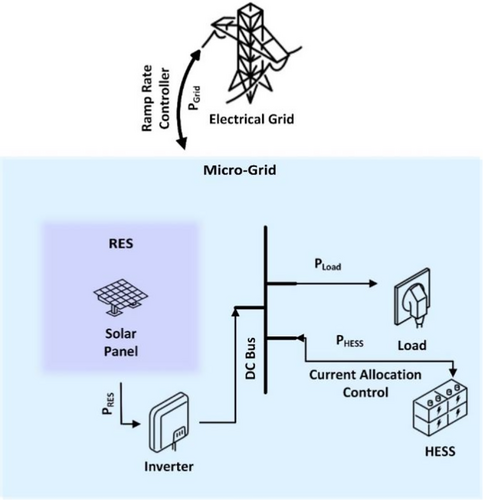
The main controllers are the ramp-rate controller and the HESS current controller. The ramp rate controller is used to control the grid power flow PGrid with the rest of the electrical network. Similarly, the HESS current controller is used to control the power allocation of PHESS to respective components of the HESS, including BESS and SC.
The current allocation to HESS is controlled by the FBM HESS current controllers. These controllers allocate the high frequency currents to the SC and lower frequency currents to the BESS. There are several FBM current allocation controllers including rule-based (FBM-RB), current sharing coefficient based (FBM-COEFF), and time varying frequency based (FBM-TVF).
The high frequency battery current raises the battery's temperature, impedance, and capacity retention, according to Reference [27]. The modeling of the relationships between these battery performance parameters and battery current frequency is very difficult, but the temperature is demonstrated to have a nearly linear connection with time when high frequency battery currents are drawn from it.
In summary, the ramp rate controller allocates the current to the HESS and the FBM HESS current controller then divides this current between the HESS components. The following sections discuss various components of the MG system and controllers in detail used for this study.
2.1 Ramp Rate Controller
The intermittent nature of RES systems is the primary issue with their integration with grid-connected MG. The grid's security is compromised as a result of this intermittency, which forces high ramp rates on it. The MG with RES system is subject to ramp-rate conditions imposed by the system operators in order to overcome this problem. These conditions are normally 10% of the rated RES value per minute, and this is also the assumption made in this study. However, any ramp-rate value can be achieved in accordance with the network operator's regulations.
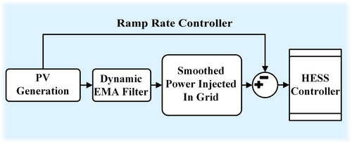
The dynamic exponential moving average (DEMA) method excels for ramp-rate management because the smoothing co-efficient (α) value in DEMA is chosen based on the violation of ramp-rate rather than at random [6]. Because of the arbitrary choice of α, the exponential moving average (EMA) approach allows excessive use of the HESS due to over-smoothing. Therefore, the DEMA controller reduces the overall HESS usage by avoiding over-smoothing. The ramp-rate controller then functions by allocating the difference of smoothed power from DEMA and the actual generation produced by RES to the HESS. The flow diagram of this process is given in Figure 2.
2.2 Current Allocation Controller
DEMA methodology reduces the overall current allocation to the HESS, but the optimal current allocation of the power allocated to the HESS is still required to maximize the BESS life. FBM current allocation is a natural answer to the allocation between high-energy and high-power components of a HESS. This section briefly discusses the conventional current allocation control techniques, which will be used for comparison with the proposed FBM-WOA technique.
Here, the represents the frequency-based filter and the , , and are the reference SC, BESS and HESS currents, respectively.
The PI current controllers of the DC-DC converters receive the reference currents mentioned above and output the desired current. The SoCs of the HESS components are uncontrolled in the conventional FBMs such as FBM-Rule Based Controllers.
2.2.1 FBM-Rule Based (FBM-RB) Controller
FBM-RB is the simplest approach towards the low-and high-frequency filtration based on the SoC levels of the HESS components. However, there is no SoC recovery feature available in this technique. The components are allowed to be in continuous operation unless the SoC boundary is reached. The SoC levels are prevented to go beyond the permissible limits based on the rules defined in the controller. Whenever a component reaches its SoC boundary, the controller immediately cuts-off its current to zero. This is called the “discontinuous operation” of the HESS and has detrimental effects on the HESS components specially the BESS life. This technique has its advantages in the sense that BESS usage is minimized since the SoC of SC is not recovered at the expense of BESS usage. However, the SoC levels cannot be controlled in FBM-RB technique and disadvantages of discontinuous operations pose threats of instability and BESS degradation.
2.2.2 FBM-Time Varying Frequency (FBM-TVF) Controller
The FBM-TVF technique, unlike the FBM-RB, can modify the current allocation to the corresponding HESS components based on the SoC levels and hence controls the SoC levels. The current allocation is determined by the operating point of the filter based on the cost functions involving the current SoC levels. This technique helps to keep the SoC levels from dropping to the lower or upper boundaries. However, this methodology is also unable to recover the SoC back to the normal range.
2.2.3 FBM-Current Sharing Co-Efficient (FBM-COEFF) Controller
As stated earlier, the FBM-TVF approach controls the SoCs of the HESS components within bounds, but it is unable to bring the SoC back to a suitable level and prepare it for the next energy demand from ramp-rate controller. In order to solve this discontinuous operation problem, loop control techniques like sharing coefficient can be effective. This technique uses one manipulated variable namely “current co-efficient (icom),” to recover the SoC back and avoid the discontinuous operation. However, the saturation of this manipulated variable can lead to the discontinuous operation.
Even though the SC SoC can be controlled tightly over a certain set value using high penalties and hard constraints, this is not the ultimate solution to improving the BESS life. The tight control over SC SoC can ensure continuous operation but leads to more usage of the BESS, reducing its cycle life. Therefore, a trade-off is necessary, which has not been used in literature and can be achieved easily by the proposed FBM-WOA technique.
2.2.4 Proposed FBM-WOA Current Allocation Controller
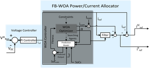
This section gives the detailed discussion on the proposed technique. The FBM-WOA utilizes two manipulated variables which counter the control saturation problem of one manipulated variable and provide more controllability, allowing the operating points to be set close to the boundaries without losing stability. However, instability can occur in any system when the State of Charge (SoC) boundaries are reached and immediate recovery is not possible, particularly if the load demand consistently drives the SoC towards its upper or lower limits. This is a physical limitation inherent to energy storage systems and is not specific to the Whale Optimization Algorithm (WOA). Nonetheless, WOA has been used in a number of research studies including energy management as well as in References [28, 29].
The control of the DC bus, which is the main control loop responsible for stability, is controlled by PID-based voltage controller, and the WOA optimization is merely used for the allocation of current generated by the voltage controller. Similarly, the MG system is used from Reference [8] and in this research, the author has performed the small signal stability of the MG system and concludes that the MG system is more stable when HESS is in continuous operation mode, meaning both BESS and SC are available for power contribution. The author has also added a communication delay in the feedback loop of the voltage controller loop, and the study shows that the MG stability is better in the case of continuous operation of HESS, that is, when both SC and BESS are in operation. The MG system remains stable for higher communication delays as compared to “BESS-only” mode.
Proposed WOA current allocation has two manipulated variables and hence has more degrees of control over the SoCs. This means that it can operate HESS in continuous operation (BESS-SC mode) leading to a more stable MG.
The various components and flow diagram of the proposed controller are displayed in Figure 3. In order to discover the optimal operating point through WOA optimization [30] and the use of two manipulated variables, the controller uses search agents (whales) to search in the search space surrounding the operating point at each time step.
The tuning of WOA parameters was conducted using a combination of grid search and random search methods. A range was defined for the population size and the number of iterations, and within this range, random values were selected and tested. This process continued until the results began to deteriorate, at which point the optimal values were identified. This structured yet flexible approach allowed for efficient exploration of the parameter space and identification of values that yielded satisfactory results.
The fitness function emphasizes the need to smooth out the sudden changes in the form of penalizing the large changes in the manipulated variables. This is special in the sense that the sudden changes, whether they be due to the discontinuous operation or the large step changes of the manipulated variables, are avoided in the proposed methodology. The purpose of including an extra manipulated variable serves the primary purpose of smoother transitions and increased controllability. This is done to avoid the sudden BESS current changes, which are the case in discontinuous operation and are extremely detrimental not only to the BESS life but also to the stability of the MG and voltage profile of the DC bus. Furthermore, the increased controllability through two manipulated variables allows the use of SC closer to its upper and lower limits, knowing that a discontinuous operation and abrupt changes can be countered easily in the form of a smooth SoC recovery.
This increased controllability allows the proposed FBM-WOA technique to control the SC SoC within the bands close to its upper and lower limits. The proposed methodology works like FBM-RB until the SoC enters that control band. The upper band is defined to be from 75% to 80% and the lower band is defined between 30% and 35% So instead of hard shut-off like in the case of the FBM-RB technique at the upper (80%) or lower (30%) SoC limit, the SC is allowed to be used until the SoC value enters the band on either side of the SoC limit and hence the advantages of both FBM-RB, which is the lower use of BESS, as well as SoC recovery to the normal operating range like in the case of FBM-COEFF are utilized with smoother transitions.
2.3 HESS Components
The MG system used in this research article is the same as in the research of Reference [8] along with the test load designed by the author. However, the modifications in the HESS design are done as mentioned in the subsequent section. The comparative study is also done using the real data from the research of Reference [31].
2.4 System Parameters
The size of the SC in test load case is taken the same as used in Reference [8] for comparison of the various current allocation techniques used in this study mentioned above to test the cases where the SoC limits of SC are reached in order to find the effects of discontinuous operations of the HESS on BESS life. Similarly, for the real load cases MG, the SC size is doubled in order to obtain longer periods of continuous operations and develop a comprehensive comparative analysis of the current allocation techniques. The parameters of various study system components are given in Table 2.
| Quantity | Value |
|---|---|
| PV rating | 66 kW |
| Charge capacity SC | 0.44 Ah (real load)/0.22 Ah (test load) |
| Nominal voltage SC | 190 V |
| Charge capacity BESS | 375 Ah (real load)/50 Ah (test load) |
| Nominal voltage BESS | 72 V |
The BESS bank is designed with practically available battery cells such as Evlithium 4IFR12.8-75-Y(26650-3.2V-4S22P) with 75 Ah and 12 V specifications. The DC voltage of 72 V is achieved by using 6 strings of 5 cells in parallel. The total capacity turns out to be 27 kWh, which is a little more than 40% of the maximum RES capacity and serves the purpose well even if utilized between 0.1 and 0.9 SoC levels as per the criterion given in Reference [32].
2.5 Solution Methodology
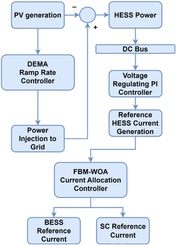
This study uses two controllers: the DEMA ramp rate controller controls the power from HESS based on ramp rate violations, and the HESS current is optimally allocated to its components using WOA. The general methodology flowchart is presented in Figure 4.
The WOA is an iterative meta-heuristic technique which exploits the predation behavior of humpback whales. The search agents are randomly spread throughout the search space and the optimal solution is found by imitating the “bubble-net” hunting strategy which involves the mathematically modeled shrinking encircling mechanism and spiral updating of positions with each iteration. Similarly, in order to avoid getting stuck in local minima, the exploration of search agents where they are randomly thrown around shrinking search space is done throughout the iterations.
The number of search agents used in this research is 50 and the search for the optimal solution is conducted for 10 iterations. It is pertinent to mention here that a search agent in this research is two dimensional containing two manipulated variables representing current sharing co-efficient and the filter co-efficient.
3 Experimental Results and Discussions
This section deals with the experimental results for comparison of the proposed FBM-WOA technique with traditional FBM methods. The proposed method is evaluated using test load and real MG load as discussed below.
3.1 Test Load Description
The test load shown in Figure 5 is made to replicate various situations like slow rising rate, sudden rise and decline in rate, and intermittent power changes. These situations arise in real MGs due to the sudden loss of load, generation, or due to the intermittent nature of RES. The test load also tests the stability of the system in stand-alone or islanded mode. The slow ramping load is put on the HESS from 0 to 8 s; then a constant load is maintained till 30 s. The sudden load inception and load rejections are mimicked at 30s and 45 s, respectively. The intermittent load changes are imposed between 65 and 75 s, and finally, a large load inception and rejection is imposed at 90 s and 110 s, respectively.

3.2 Battery Current
The simulation results of the battery currents for the various methods employed in this study are displayed in Figure 6. The BESS supplies the high frequency current and peak currents required by the ramp-rate controller when the SC energy is exhausted.
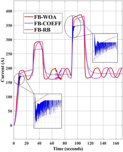
It is evident from the current profiles that the FBM-RB does not account for the avoidance of the HESS's discontinuous functioning. Our study's primary concern is the BESS system's life, and highly changing currents drastically shorten its life. Such discontinuous operation in FBM-RB is depicted in the zoomed-in version of Figure 6a,b where it can be seen that from 7.5–11 s and 91.5–94 s, the battery current for FBM-RB has huge undesirable fluctuations.
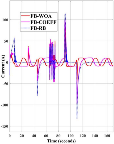
3.3 Super Capacitor Current
Figure 7 displays the SC current simulation profile for each of the available methods in literature discussed in this paper. It is evident that the SC current in the FBM-RB method abruptly decreases to zero to prevent over-limit violations of hard constraints at times when the load abruptly changes (or the SC energy is expended), close to the 7.5–10 s and 91.5–94 s time intervals. As a result, BESS delivers peaks and the stability point moves to a nearly unstable zone, inflicting high frequency currents on the device.
3.4 SoC Variation in HESS
The SoC levels of BESS in the FBM-WOA, FBM-COEFF, and FBM-RB control configurations are shown in Figure 8. Since the energy from the SC is consumed at the expense of reaching its boundary level, the SoC in the case of FBM-RB is the largest.
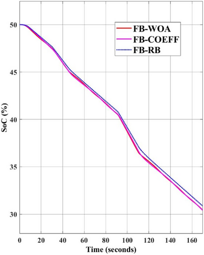
This preserves the BESS SoC, but it also exhausts the high-power component, which causes the HESS to operate discontinuously. Power oscillations are caused on the high energy component, or BESS in our case, whenever SC reaches its boundary level and its current allocation is abruptly forced to zero. Because of the supply of peak currents, the FBM-RB scenario may result in early BESS deterioration even if it uses less BESS than the FBM-COEFF and FBM-WOA techniques.
The simulation results of the SC SoC levels employing various current allocation controller algorithms are displayed in Figure 9. The FBM-RB section illustrates that SoC reaches its limit between approximately 7 and 45 s, and likewise between 90 and 115 s. This is the result of the controller's lack of SoC recovery capability and can consequently cause the instability of the MG system.
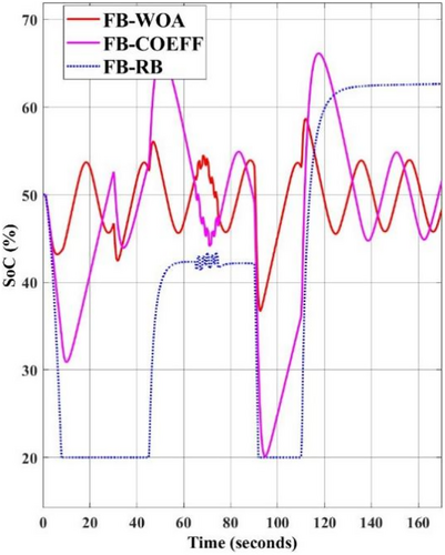
The FBM-WOA and FBM-COEFF curves, on the other hand, demonstrate the capacity to maintain SoC near the predetermined 50% mark. Furthermore, because the FBM-WOA controller has two controlled variables that can regulate this set point, its advantage in maintaining the SoC level closer to the set point is considerably greater. Moreover, this results in more consistent quality metrics like a smoother DC bus voltage and battery current. The FBM-COEFF curve (magenta line), which reaches the lower bound at about 90 s, is another observation that supports the suggestion that the proposed method has greater control. But there must be a trade-off between using BESS and tighter control, which is guaranteed by the proposed technique's capacity for optimization. Likewise, Figures 10 and 11 clearly show that, in the case of the proposed technique, the two manipulated variables offer stronger control over the SC SoC to maintain its availability for guaranteed continuous operation.
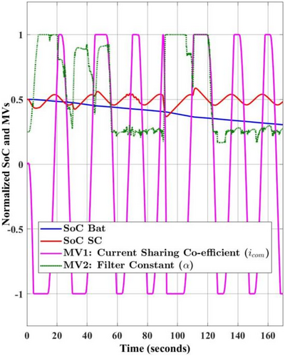
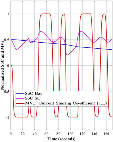
As evident from these figures, in the case of FBM-COEFF, the current sharing co-efficient (icom) saturates for longer periods of time; for example, from around 10 s up to 30 s. Whereas, for the same conditions, two manipulated variables help recover the control from saturation much quicker in the case of FBM-WOA, and the current sharing co-efficient (icom) saturates only for 5 s (10–15 s).
3.5 Bus Voltage
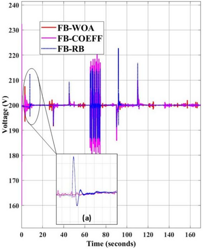
The DC link bus voltages of the simulation results from various methods are displayed for comparison in Figure 12. It is evident that the FBM-WOA case has the smoothest voltage because it can effectively manage the energies allocation of the HESS components and prevent abrupt changes. The FBM-COEFF and the suggested FBM-WOA control methods provide a considerably better voltage profile due to the smoother current transitions, whereas the FB-RB control methods exhibit the most flicker in the DC bus voltage. Ignoring the stabilization phase at the start, the largest flicker is observed in FBM-RB at 95 s and the voltage shoots above 220 V. Similarly, between 7.5 and 8 s the voltage spike in the FBM-RB is largest in comparison to FBM-COEFF and FBM-WOA, as shown in the zoomed version of Figure 12a.
3.6 Real HESS Load Testing
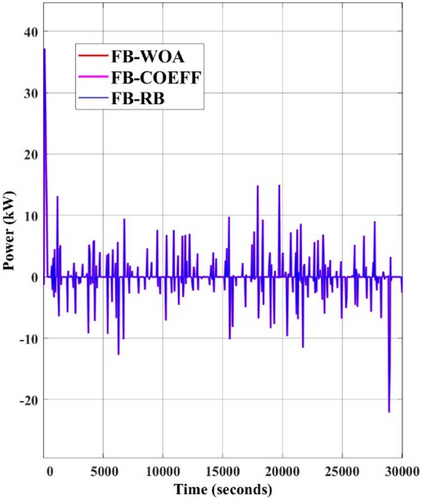
The real load data is converted into the signal of RES generation, and various days of the year have been used for testing in this study. The ramp-rate controller smooths the load from the RES generation as per the ramp-rate, injects it into the grid, and feeds the difference to the HESS controller. One such load difference applied to the DC bus by the ramp-rate controller is depicted in Figure 13.
The improvement in the bus voltages and BESS life in the real load case is similar to the test load scenario for the proposed FBM-WOA case. This improvement owes to the better control of the proposed technique. Figure 14 shows how the manipulated variables work to restore the SC SoC (FB-WOA case) to the reference value when it approaches the soft limit of 70% near 50 s. The second manipulated variable (α) can be gradually increased to give the SC less power as the current sharing coefficient approaches its maximum value. Once the SC SoC is regulated below the upper threshold, the α is gradually reduced to allow the SC to once more absorb high-frequency current allocation.
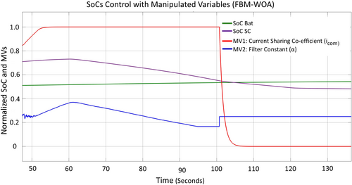
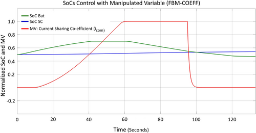
This is where the proposed technique outperforms the currently available single-manipulated control methods since it guarantees the goal of attaining the HESS's continuous operation. Similarly, the current sharing coefficient, the single manipulated variable in Figure 15, saturates after 60 s. For this reason, softening the SoC upper limit constraint could result in serious SoC limit violations.
3.7 Battery Capacity Loss
In terms of enhancing the total BESS life, the proposed technique is superior, as evident by the lowest value of life loss percentage. In terms of SoC recovery and battery current transitions, this technique outperforms the present FBM-RB and FBM-COEFF methods whenever the SoC boundaries are tested. Moreover, as the previous test load example demonstrated, there is a considerable danger of instability, intermittent operation, and high frequency/peak current allocation to BESS in FBM-RB.
Table 3 compares the battery capacity loss for test load and real load scenarios. For real load cases, random days have been selected from different seasons of the year. These days represent the wide spectrum of the RESS behavior throughout the year and hence ensure the validity of the claim of improved BESS life when the proposed FBM-WOA technique is used for current allocation.
| BESS capacity loss (%) | |||||||
|---|---|---|---|---|---|---|---|
| Real load | |||||||
| Current allocation technique | Test load | 2-Jan | 14-Feb | 3-Apr | 15-May | 1-Jul | Average |
| FBM-WOA | 0.04303 | 0.1814 | 0.2041 | 0.3075 | 0.30529 | 0.2998 | 0.259618 |
| FBM-RB | 0.04314 | 0.1845 | 0.2075 | 0.3119 | 0.30903 | 0.3040 | 0.263386 |
| FBM-COEFF | 0.04802 | 0.1856 | 0.2089 | 0.3149 | 0.31224 | 0.3070 | 0.265728 |
The increased life loss for the Real Load case of the FBM-COEFF is due to the increased usage of the BESS. In the Test Load case, the FBM-RB performs poorly due to the imposed high-frequency current on the BESS due to discontinuous operation. However, the proposed FBM-WOA technique outperforms the existing FBM-RB and FBM-COEFF techniques in all scenarios.
4 Conclusion
The paper provides insight into how to integrate MG-RES systems with improved security, stability, and HESS life. It is concluded that the high-energy and high-power exchange between the power grid and the associated MG is naturally solved by the HESS. In addition to improving the MG characteristics, HESS also enhances the MG-RES connection stability. DEMA-based ramp rate controller can lower the usage of the HESS by preventing the over-smoothing of the HESS power requirement during high ramp rates.
It has been shown that the induced high frequency power flow caused by the HESS's discontinues operation shortens the BESS system's lifespan in addition to endangering the MG's stability. Because the BESS is the only component of the HESS that is available during discontinuous operation, it is used to supply the highly fluctuating reference current produced by the PI controller when the DC bus voltage control loop becomes unstable due to the abrupt reduction in SC current.
The discontinuous operation can be avoided by using tighter control over the SoC of the SC. Many FBM techniques such as FBM-COEFF, FBM-TVF, and FBM-RB have different approaches and advantages over one another, and this research proposes a hybrid combination of these techniques. To utilize the benefits of the above-mentioned techniques, two manipulated variables have been used, which enable tighter control over the SoC. This is advantageous compared to the single manipulated variable control, which has problems of control saturation, and hence the control over the SoC is lost at times of high-power demands from HESS.
Better management of the SoC of both HESS components is offered by the proposed FBM-WOA hybrid controller for the HESS current allocation. According to the comparative analysis, this optimal current allocation controller enhances the stability and lifespan of the HESS. The proposed technique decreases the BESS percentage life loss by 11.59% and 0.25% as compared to rule-based (FB-RB) and current sharing coefficient (FB-COEFF) methods respectively for the test load case; similarly, it reduces average BESS life loss by 1.45% and 2.35% as compared to FB-RB and FB-COEFF for real load cases of five different days of the year. This is achieved by maintaining the HESS system's continuous operation within its normal operating range and by smoothing out the BESS current around SC SoC limits, thereby ensuring that the SC is always ready to counteract the highly fluctuating reference current that is required by the voltage control loop.
5 Limitations and Future Work
The simulation results show that the proposed FBM-WOA approach has minimal battery life degradation as compared to other techniques, and it is important to mention here that the BESS life loss modeling used is based on an empirical model, and the power constant is assumed to be a constant value, which is a fair assumption since the power law constant remains nearly constant for various conditions. Similarly, the power converters are modeled using PI gain loops for simplification and do not include the real-world dynamics of power converters, which is not important for this particular study since the main focus is on the optimal use of HESS. However, the power converters in this study include the inductances and resistances of the power converter filters, making it somewhat realistic, as defined in the study of Reference [8]. The capacitance of the MG DC link bus has also been incorporated. The author of Reference [8] added communication delays in milliseconds (ms) in the feedback loop of the voltage controller loop and has performed small-signal stability of the MG system as well for imitating realistic behavior. Similarly, the response time of the modern power converters is in microseconds (μs) [33] which is much lower than the overall control time of the MG used in this study, and hence will not have much impact on the results of this study.
The simulations are carried out only for 8 h due to the complex models involved, and the validity of the study remains intact since these 8 h essentially capture the whole daylight generation period of the given PV during which the ramp-rate violations can potentially occur. Furthermore, the simulations are carried out for different days of the year from various seasons to ensure the validity of the results.
The future research work can include a comparative study of various optimization techniques to single out the best performing optimization method best suited for the current allocation of HESS. The research work can be extended to increasing the simulation time and including practical power converter models to test these optimization techniques more rigorously.
Author Contributions
Nouman Alam Siddiqui: conceptualization, methodology, software, writing – original draft, data curation. Hira Tahir: writing – review and editing, methodology, software, data curation, conceptualization, investigation. Muhammad Akram: supervision, formal analysis, validation. Habib Ullah Manzoor: visualization, project administration, resources.
Conflicts of Interest
The authors declare no conflicts of interest.
Open Research
Data Availability Statement
The data that support the findings of this study are available from the corresponding author upon reasonable request.


