Impact of Bidirectional Semiconductor Devices on DC and Hybrid Microgrids Enhanced by Wide Bandgap Materials
ABSTRACT
Electric vehicles (EVs) are emerging as a leading option for traveling while considering the reduction in greenhouse gases (GHG) and corresponding expenditure of fossil fuels. Besides, microgrid (MG) operations pave the way for the development of renewable resources (RRs) based EV charging stations. The paper presents charging circuitry for EVs, designed with a two-stage conversion mechanism, DC-DC and hybrid grid in the MATLAB (SIMULINK) environment while using wide bandgap (WBG) semiconductors (SCs) like IGBTs and MESFETs. Power flow in DC and Hybrid-microgrid (HMG) is supplied with the help of an isolated bidirectional battery charger with the potential of 1.5 kW at 120 V. The AC-DC conversion is achieved through an inverter, while the rectification mechanism is used for DC-DC conversion. The designed circuitry also employs four switches, operating at a high frequency, used with a PI controller to maintain the output of 120 V DC for battery charging. The remaining two controllers in the presented circuitry are used for the discharge system of the battery. The paper also presents a detailed comparative analysis of the conduction losses, measured for EV integration and future interventions while considering WBG-SCs. The examination of the achieved results reveals that minimum losses are in the case of the DC grid system. The investigation of the results also shows lesser harmonic distortion for the DC grid in contrast to the other considered case. Results underline the insinuations of substance-synchronized EV charging to condense adversative functioning impacts and associated ventures.
1 Introduction
Carbon and nitrogen oxide emissions from conventional powerhouses and vehicles cause about 60% of total air pollution and have very severe climate impacts [1-3]. Dominantly, the transportation sector depends on crude oil products (i.e., petrol, diesel, etc.) with CNG and LPG being cheaper alternatives available in some countries that make up around 95% of existing transport networks. This results in greenhouse gas emissions creating air pollution and other environmental hazards [4, 5]. Additionally, these conventional resources are also very costly and are depleting at a high rate due to their extensive utilization. For generation purposes, it is the basic need to burn the fossil fuels, but, as mentioned that they are not environmentally friendly, and this situation is responsible for climate change [6-8].
- Enhancement of the local reliability,
- Feeder losses reduction,
- Provide support to the local voltage,
- Correction of the sag voltage,
- Provide Uninterruptable supply.
Microgrids (MGs) have two operational modes, namely, islanded and grid-connected modes, and the main component to be controlled is the inverter in any MG. The primary focus of any MG is to provide assistance in economically optimizing the power system, and the necessary control features of the MGs are discussed in [14-18]. The aim of incorporating electric vehicles (EVs) in the existing transport networks emphasizes the implementation of RR-based MGs to facilitate local power generation without increasing hazardous emissions.
The high-efficiency power conversion systems are crucial for modern MGs and EV charging infrastructure. Current disadvantages of traditional silicon-based semiconductors include low power handling and device operation at elevated temperatures. Their high thermal conductivity, higher breakdown voltage, and faster switching speeds make them superior to Si devices. Wide bandgap (WBG) materials such as Gallium Nitride (GaN) and silicon Carbide (SiC) have emerged as alternatives to Si. Such attributes also greatly contribute to the efficiency and performance of power electronics in bidirectional converters, which are well suited for application in MGs and EVs [19].
WBG-based power semiconductor devices, including Metal–Semiconductor Field-Effect Transistors (MESFETs) and Insulated-Gate Bipolar Transistors (IGBTs), enable high-frequency operation and reduced conduction losses. Their capability to withstand higher voltages and temperatures allows for more compact and energy-efficient designs in EV charging and power conversion systems [20, 21]. WBG-based power semiconductor devices, including Metal–Semiconductor Field-Effect Transistors (MESFETs) and Insulated-Gate Bipolar Transistors (IGBTs), enable high-frequency operation and reduced conduction losses. Their capability to withstand higher voltages and temperatures allows for more compact and energy-efficient designs in EV charging and power conversion systems. The environmental and economic benefits along with the various facilitating policies made by governments globally, the EVs are becoming very popular among private investors [22-24]. However, the EV's also have some drawbacks like initial price, the short distance covered, battery charging time and lack of the infrastructure for the charging of vehicles are the major reasons for currently lower share of the EVs in global transport network. Besides, in the currently implemented power system, the EV's charging result in over-loading of the transformers. Therefore, for increasing the share of EVs in the transport network, the current and future enhancement of cleaner power generation should also be considered at the planning stage [25-27].
GaN and SiC devices are increasingly capturing the electronics market, specifically in EVs, RRs, high-frequency applications, and aerospace. WBG materials can aid in high-temperature operations and power densities if the challenges attributed to their manufacturing can be compensated. These WBG and UWBG materials have the capability of ultimately replacing Si in the entire continuum of power electronics. They can influence the design and development of energy-efficient, high-performance, and next-generation devices. The authors in the article [28] summarized the difficulties, uses, physical characteristics, and competitive environment of WBG power electronic circuitries, like lately developed diamond technology.
WBG materials are widely adopted in power electronic applications due to the need to transition in energy phenomena worldwide. The nature of the GaN and SiC devices, however, makes them essential in developing next-generation bidirectional converters based on higher efficiency, reliability, and sustainability in EV charging networks. This paper investigates how WBG-based bidirectional converters affect DC and hybrid MGs in power flow management, efficiency, and not the least, conduction losses. MESFETs and IGBTs are compared to reveal advantages of WBG semiconductors in reducing energy dissipation as well as in strengthening the overall system stability.
The rest of this paper discusses the findings of researchers in the field of WBG power electronics and how they can be applied to future networks and sustainable transportation. Besides, the combined structure for the fleet of EVs is examined in the scale of hours. For the future calculation of Electric Grid studies, the precise model of the battery is the basic requirement with the consideration of EVs integration in ON/OFF time. The size and other constraints of the Electric grid will be influenced by the period of the EVs connection to the grid as [29-31]. The prominent contributions made by the researchers in the field of EV development and deployment are presented in the next section with the consideration of various significant EV parameters.
2 Literature Review
The industrial revolution started in the nineteenth century with the incorporation of steam powered stations due to excessive availability of coal and lack of knowledge about their environmental impact. The industrialists at the time developed steam powered cars [32], but they were inefficient due to the requirement of large and heavy components used in the car [33]. In addition, this was time-taking process [34]. Theses steam cars had many other disadvantages, like slow operation of the engine, excessive vibrations, and lesser control on driving [35]. However, the people started working on other possible technologies to make more fuel-efficient vehicles.
The authors in [36] analyze the progressive impact of incorporating WBG semiconductors in the design of power electronic converters. The paper discusses important characteristics like better thermal conductivity, higher breakdown voltages, and faster switching speeds. The authors examine how better performance against the mentioned attributes like different voltage levels improves the overall efficiency of the converters and enhances the performance of modern EVs with respect to varying power applications. Besides, the authors also analyze the important design considerations for better performance of EVs.
The continued efforts of the researchers yielded fossil fuel-based vehicles which were more efficient than steam-powered cars and had better operational features that made cars the most common source of transportation [37, 38]. These fossil fuels were much cheaper and more efficient at the time, and the climatic conditions were better, so the world did not pay attention to the forthcoming issue of their depletion and the generated pollution at that time [39].
During the last two to three decades, an alarming situation arose around the world known as global warming that caused severe changes in weather patterns and an increase in natural disasters like excessive rains, floods in some areas, and impactful droughts in other areas [40, 41]. The researchers concluded that excessive use of fossil fuels for increasing power demand and transportation has altered the global ecological balance due to an extensive increase in emissions of hazardous GHGs [42, 43]. These factors motivated researchers to develop various cleaner alternatives for the necessary power generation and transportation [44].
Now-a-days, the share of EVs in the transportation system is increasing significantly (from 0.1% in 2014) due to various technological improvements [45]. According to recent surveys, the fossil fuel dependency of the transport sector reduced to 95% due to the gradual increase in the number of EVs, and this trend is increasing continuously [46]. This trend is also encouraged by many governments; for example, in EU, strict penalties are enforced on breaching the fixed limit of CO2 emissions [47]. The issue of EV charging is also addressed by the developers, and the prominent topologies for the purpose are discussed in the next sub-sections.
The article [48] presents an interconnected multimodule, WBG-based DC to DC converter designed according to the DAB topographic anatomy for EVs. These converters are developed to enhance power density and working efficiency. The examination of these SCs is performed through 85% of the total power of 500 kW, while the other segment extracts 15% of the total power. The fast charging is accomplished through switching frequencies of 10 to 200 kHz for both above-mentioned segments. The researchers analyzed the conduction losses of both segments and quoted an efficiency of 99.25% and a density of 10.99 kW/L at 200 kHz fast switching.
The development of EV chargers depends on various factors like the availability of the source, types of batteries, charging time, and current number of EVs on the road during a particular period. There are two commonly implemented topologies for the charging of the battery; one is called a single-stage converter, and the other is known as 2-stage converters, as shown in Figure 1. For the low power rating, a single-stage topology is used in which there is no need for galvanic isolation, like a transformer is needed in this type. These types of chargers are also known as non-isolated battery chargers.

The function of the single stage controller is to perform the process of rectification such as AC-DC conversion, and power factor correction is also done during this conversion. For the fast charging of the battery, DC-DC conversion is also required. The size and weight of these chargers are small due to fewer components, and their costs are also less than the two stage chargers. However, the charging time of these chargers is not very appreciable due to the low power rating.
The second type of the chargers is two-stage chargers that are used for the fast charging of EVs, and it is possible due to their high-power rating. These chargers require high-frequency transformers due to the requirement of galvanic isolation to accommodate the high power rating of the two-stage transformers. The block diagram of these two-stage chargers is presented in Figure 2. It is also very important to provide protection in fault conditions; also, this transformer works as voltage conversion, such as for buck operation and for the boost operation according to the charging and discharging mode.

In this type, the 2 controller is used. One controller performs the process of rectification, such as from AC to DC with power factor correction. A DC link capacitor is also used, which is controlled by another controller and performs the conversion process like DC to DC. This conversion is used to attain the DC voltage at the output terminal. They are both types: single-phase and 3-phase. The selection process is done according to the power rating.
2.1 G2V Charging Topology
EVs require an external source for the charging of the batteries, and traditionally it has been the electric supply from the electric grid to serve the purpose. The charger used for the purpose is a rectifier since the conventional grids supply only AC power to the consumers, and it requires conversion to DC for charging the batteries [49].
To improve the charging time at the EV charging stations, an extra DC-DC converter is now implemented for more efficient conversion and fast charging. These chargers can be on or off board, depending on the level of charging and the current status of the battery [50].
With the aim of improving the mobility of the EVs, their weight must be kept in check, and structures were to be made more compact. But the on-board chargers have issues like lower power rating, and their traditional designs are not supportive for facilitating fast charging. On the other hand, the off-board chargers are normally situated at locations where the size of the charger is secondary; thus, DC-DC converters are easily added to support the fast charging of EVs [51, 52].
The G2V operation works with the power transferred from the grid used to charge the EV through a BUCK converter, and the working mechanism of this type of charger is presented in Figure 3.

2.2 V2G Charging Topology
In contrast to the G2V topology, in the V2G mechanism the power flows between EV batteries and the electric grid. This V2G topology facilitates the power flow from the EVs to the grid or other utilities so they actually start behaving as a source as well [42]. This mechanism also improves the load management of the utility as the EVs can be charged during the off-peak hours for traveling or storage purposes. These charged EVs can also be used as a local power supplier during the peak hours [53-55].
- vehicle-vehicle (V2V),
- vehicle-building (V2B) or vehicle-home (V2H) and
- the vehicle-grid(V2G).
The charge stored in the batteries of EVs is used to supply the backup power in all the above-mentioned categories, which helps in load sharing for the electric grid during the peak load hours. This also solves an important issue of EV charging as well, since EV charging has been considered an additional load on the already fully/overloaded electric grids in various countries. Besides, this concept can also be enhanced commercially if a proper business model is implemented where both the consumers and suppliers can benefit. Thus, proper scheduling of EV charging can provide important technical and financial benefits [56-58].
The operational process of V2G is reversed as the battery of EV supplies its energy to the grid or some other consumer(s) through a BOOST converter and its operational mechanism is presented in Figure 4.

2.3 Charging Levels
The international electromechanical commission (IEC) and the society of the automotive engineer (SAE) have developed international standards for the charging of EVs that are overviewed in Table 1 given below [59-62]:
| Sr. | Power level | Level 1 | Level 2 | Level 3 |
|---|---|---|---|---|
| 1 | Grid voltage (VAC) | US (120) | US (240) | 208–600 VAC or VDC |
| EU (230) | EU (400) | |||
| 2 | Power range | ≤ 3.7 kW | 3.7–22 kW | > 50 kW |
| 3 | Approximate time of charging | 11–36 h | 1–6 h | 0.2–1 h |
| 4 | Topology of charger | On-board | On-board | Off board |
| 5 | Type of grid supply | 1-phase | 1 or 3 phase | 3-phase |
| 6 | Type of charging | Slow charge | Semi-fast charge | Fast charge |
| 7 | Capacity of battery | 15–50 kW | 15–50 kW | 15–50 kW |
The diffusion of EVs into smart grid has gone through a great progress, facilitating two-way flow of electric power. The EVs charged during the off-peak hours, supply power during the peak hours for various purposes mentioned in the Section 2.2. More benefits from the EV's batteries can be retrieved by more enhancement in the equipment thus emphasizing the development of an efficient bidirectional charger [63].
2.3.1 Problem Statement
With the increasing penetration of EVs in the global transportation network, the national grids are facing a rise in their load demand, fluctuations in supply voltage, increasing losses in the power electronic circuitry, and deteriorating power quality due to an increase in harmonics. Therefore, it is necessary to analyze the connectivity of the fleet of EVs in the DC and Hybrid microgrid (HMG). It can help in reducing the load on traditional electric grids, declining hazardous emissions, and increasing charger efficiency. Thus, it improves the charging time of EVs and paves the way for their better integration into the global transport networks.
2.3.2 Objectives
- Development of control techniques for the charging and discharging of EVs,
- Simulate the Charging/Discharging of EV in DC and Hybrid microgrid,
- Analyze the performance of EV in DC and hybrid microgrid,
- Perform calculation of the conduction losses during charging and discharging.
2.3.3 Methodology
The EV battery chargers can be used for the unidirectional as well as bidirectional power flow depending upon the condition of the circuit. For the rectification process of single-phase systems, mostly IGBT topology is used, and for bi-directional H-bridge rectifiers are used. The circuit diagram of the system is shown (Table 1) in Figure 5.
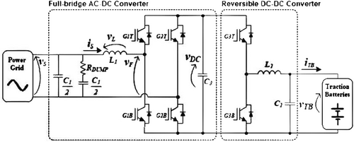
The proposed 1-phase or 3-phase, whether it is isolated or non-isolated battery charger it has at least one of the following drawbacks.
2.3.4 Proposed System
To avoid various problems and operational limitations mentioned in the above sections, the paper presents a bi-directional battery charger. The presented battery charger is designed for a 1-ϕ AC source, DC source, and HMG, and it is responsible for both operations such as V2G and G2V operation. The construction of the proposed system is discussed in this section.
2.4 Construction for DC Grid
2.4.1 Charging Mode (G2V)
During the charging mode, the DC voltages are applied to the switches that convert them to the AC voltages which are then supplied to the high-frequency transformer. This transformer acts as a buck converter during the charging operation and the AC supply is converted into the DC through a full-wave rectifier to charge the battery as shown in Figure 6.

The desired output voltages are maintained by using the PI controller.
2.4.2 Discharging Mode (V2G)
During the discharging mode, the battery voltages from EV are applied to the switches to convert them into the AC voltage. These voltages are provided to the transformer which acts as a boost transformer and the boosted voltages are supplied to the full bridge rectifier which then converts these AC voltages into DC for supplying it to the grid as shown in Figure 7. The desired voltages are maintained using a PI controller circuit.

2.5 Construction of Hybrid Microgrid (HMG)
2.5.1 Charging Mode (G2V)
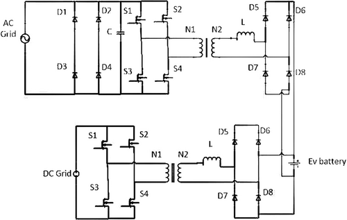
During the charging mode of a HMG of the EV, it can both be charged by AC as well as a DC grid. In this topology, the AC supply from the grid is converted into DC through a two-stage mechanism and the supply from the DC grid buck the supply for charging the battery of the EV. The Figure 8 presents the proposed HMG topology.
2.5.2 Discharging Mode (V2G)
During the discharging operation, DC supply from the battery is returned to the AC and DC grids according to the requirement. The IGBTs in the circuitry serve as switches while the switches start working as IGBTs. The high frequency transformer works in the boost mode for the AC and DC grids, respectively.
2.6 PI Controller
The PI controller is used as a feed-forward controller for the grid voltages and is denoted by Vg. The inverter current, which is also used as feedback, is denoted as Li and it is also used as the reference value. Figure 9 shows the circuit diagram for the feedback PI controller.

2.7 PR Controller
The Figure 10 presents the PR controller circuitry in which the feedback inverter current and reference grid voltage are represented as Li and Vg, respectively.

2.8 LCL Filter Design Consideration
- Total inductance (L1+L2) must be less than 10%, this avoids the large voltage drop across the inductor.
- The ripple current must be 20% of the rated current.
- The capacitance should be of moderate values (i.e., medium range).
- The inverter harmonics must be limited according to the IEEE standard.
The unipolar modulation is renowned for its high efficiency, where the switching frequency is double that of the carrier frequency, which keeps the size of the filter smaller as well.
2.9 Conduction Losses
- The device is in ON-state.
- The device is conducting.
- The device is in the OFF state.
However, the switching frequency does not impact the conduction losses and varies according to the duty cycle.
2.10 Switching Losses
2.11 IGBT Losses
2.12 Total Losses
3 Simulation and Results
A 1.5 kW isolated battery charger with a voltage of 120 V is constructed, and the battery is charged through single-phase, DC, and HMG sources while the simulation is performed using Simulink in MATLAB. The designed charger circuitry can also discharge the battery as a backup of the AC grid whenever power is required. The nominal frequency of the charger is set at 50 Hz, while the switching frequency can go as high as 20 kHz. The input voltage for the 1-ϕ AC supply is set at 220 V, and it remains the same for DC and HMG sources, while the output is set at 120 V.
The designed parameters of the developed battery charger are given in Table 2 and these values are used for the simulation in Simulink. These parameters remain the same for all three cases of DC and HMG sources.
| Sr. no. | Parameters | Values |
|---|---|---|
| 1 | Inductor (Li) at source side | 400e-6 |
| 2 | Source side capacitor | 100e-3 |
| 3 | Inverter side inductor Lg | 100e-3 |
| 4 | DC link bus capacitor | 500e-6 |
| 5 | Primary winding of transformer | 220 V |
| 6 | Secondary winding of Transformer | 120 V |
| 7 | Output capacitor | 100e-3 |
3.1 DC Grid
3.1.1 Charging Mode (G2V)
While operating in charging mode, the charging of the battery is done by the DC Grid, which has a voltage of 220 V, and this voltage is DC, and the 120 V of the battery is also DC. This 120 V is maintained by the PI controller, as shown in Figure 11.

The Figure 11 presents the voltage vs. time graphs for the designed charging mechanisms. As the figure shows, the process initiates with DV voltages at zero value that steadily rises to the required 120 V within a few milliseconds. Once the required voltage level is achieved, the PI controller maintains the voltage steadily at this value.
3.1.2 Discharging Mode (V2G)
In the discharging mode, the battery is discharged and supplies energy to the DC grid. The DC grid has a voltage of 220 V DC. These voltages are maintained by the PI controller, as shown in Figure 12.
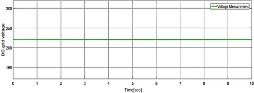
The voltage regulation is necessary as the supply is provided to the load for necessary operations.
3.2 Hybrid Grid
3.2.1 Charging Mode (G2V)
In the charging mode, the battery is charged by the DC and AC source. The battery voltage is maintained at 120 V DC by the help of a PI controller, as shown in Figure 13.

In contrast to the charging mode for the DC grids, the hybrid grids take less time to achieve the required voltage level as shown in Figure 13.
3.2.2 Discharging Mode (V2G)
In the discharging mode, the battery is used to supply the AC voltage to the AC grid and the DC voltage to the DC grid. This is done with the help of a PI controller and a PR controller, as shown in Figure 14.
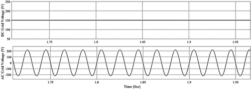
Since the battery is supplying both AC and DC grids, effective, individual voltage regulation for both modes is required. So, a PI controller is employed for DC voltage regulation and a PR controller is used for AC voltage regulation.
3.3 THD in Grid Connected Mode
Since the hybrid grid 0mechanism involved AC supply, there is a possibility of harmonic distortion that can harmfully impact the power quality. The Figure 15 presents the THD for the proposed system in MATLAB FFT Analysis via Powergui Interface.
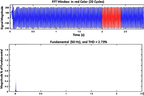
The THD in grid-connected mode is allowed to be 5%. The proposed system has a THD of 2.37%, as shown in Figure 15. It is observed via FFT Analysis window in Powergui of Simulink.
4 Comparison of Conduction Losses
Table 3 provides a comparative analysis for the losses encountered by the DC and HMG while using IGBTs and MESFETs.
| No. | Results (W) | MESFET | IGBT |
|---|---|---|---|
| 1 | P (conduction losses) | 9.36 | 11.94 |
| 2 | P (switching losses) | 2.084 | 18.14 |
| 3 | P (total losses) | 11.4 | 30.08 |
| 4 | AC grid losses | 11.4*8 = 91.2 | 30.08*4 = 120.32 |
| 5 | DC grid losses | 11.4*4 = 45.6 | 30.08*4 = 120.32 |
| 6 | Hybrid grid Losses | 114*12 = 136.8 | 30.8*8 = 246.4 |
The Table 3 depicted significant results while frolicking DC and hybrid microgrid losses. P conduction losses were found 9.3 W in MESFET while 11.94 W in IGBT. Whereas P switching losses were found high in IGBT 18.14 W and low in MESFET 2.084 W. Average P total losses showed 30.08 W in IGBT and 11.4 W found in MESFET. Significant DC grid 120.32 W losses were again found in IGBT but minimum DC grid losses were found in MESFET 45.6 W. Hybrid grid losses were found minimum in MESFET with 136.8 W while maximum losses were found 246.4 W in IGBT. Results revealed that maximum losses were found in AC grid while minimum losses shown in DC grid system. While the harmonic distortion in the case of DC grid is also very low as compared to the others.
5 Conclusion and Future Works
5.1 Conclusion
The advantages of using wide bandgap (WBG) semiconductors for bidirectional power converters on DC and hybrid microgrids have been demonstrated by this study. The results show clearly that both SiC and GaN create the same sort of impact on power conversion efficiency, reducing conduction losses, and allowing for high-frequency operation. An analysis is conducted to show how MESFETs and IGBTs compare with WBG devices in that they optimize the energy flow and grid stability.
Results of realization and performance evaluation of bidirectional converters with emphasis on the energy efficiency impact of WBG materials are presented in this paper. The results show that the conduction losses of DC grids are lower than hybrid microgrids and thus they are better suited for integrating electric vehicles to modern power systems. The second point of the study is that advanced semiconductor technologies are useful for the power management of EV charging infrastructure.
Following that work, future research will be to expand the system to accommodate more EV fleets, and then integrate predictive control techniques and real-time grid optimization schemes. Increased sustainable and resilient energy networks require continued advancement of WBG-based power electronics. Because of the minimum conduction losses in the DC grid, it is the best one in the case of Electric vehicle integration.
5.2 Future Work
- This mechanism may extend the system to more parking slots and EVs.
- This research work can be implemented using MPC to predict the arrival and departure of EVs.
- It is suggested that this work can be further extended for market-based and real-time operations.
- This work can be used for future recommendation of the Grid selection.
Author Contributions
Abdul Waheed: conceptualization, methodology, data curation, validation, investigation, writing – original draft, writing – review and editing. Saif ur Rahman: writing – review and editing, visualization, validation, methodology, formal analysis, resources, supervision, data curation, conceptualization, investigation, funding acquisition. Raheem Sarwar: funding acquisition, investigation, conceptualization, validation, visualization, methodology, software, formal analysis, project administration, supervision, resources, writing – review and editing.
Conflicts of Interest
The authors declare no conflicts of interest.
Open Research
Data Availability Statement
The data that support the findings of this study are available from the corresponding author upon reasonable request.


