Study on Harmonic Suppression Method of Permanent Magnet Synchronous Motor in High Voltage Wire Inspection Robot
Funding: This research was funded by the R&D Program of State Grid Jiangsu Electric Power Co. Ltd. (J2022135).
ABSTRACT
The working environment for safety inspection of high-voltage wires is very harsh, such as high temperature, low temperature, high altitude, wind, and rain weather, etc. High-voltage wire inspection robots can replace human work. For the robot, the harmonic suppression of the permanent magnet synchronous motor will determine the completion of inspection work. Therefore, from the point of view of the control algorithm, this paper analyzes the speed, time, and frequency domain signals of the motor driven by the Space Vector Modulation DTC (SVM-DTC) method. Then, the d-axis current is equal to zero in the adjustment control algorithm, and a direct torque control method of the permanent magnet synchronous motor space vector modulation based on time-varying flux amplitude is proposed. This control algorithm can effectively suppress the amplitude of harmonic components while reducing the fluctuation of the rotational speed signal in the time domain. After the improved motor control strategy, the torque fluctuation of the motor decreased by 42.86%. It greatly improves the stability of the robot in the operation of high-voltage electric wire. Finally, the effectiveness of this method is verified by experiments.
1 Introduction
The safety inspection of high-voltage power lines is to ensure the safety of users, road conditions, lines, and surrounding environment facilities [1, 2]. The environment of high-voltage wires is diverse and very harsh, such as high temperature, low temperature, high altitude, wind, rain weather, etc. [3]. Therefore, many high-voltage wire inspection equipment manufacturers have begun to produce wire inspection unmanned robots. The permanent magnet synchronous motor is the core component of driving in the inspection unmanned robot [4, 5]. However, there is a torque ripple problem in the operation of the permanent magnet synchronous motor. The robot application scenario requires repeated rotation, which makes other high-end equipment motors (such as machine tool spindles and electric spindles) have different working conditions. Low torque ripple directly affects the positioning accuracy and motion smoothness of the robot. The fluctuation of torque ripple will lead to inaccurate positioning of the robot, which will affect its accuracy and stability. Relevant scholars have also conducted some scientific research.
Srihari et al. [6] achieved the ideal selection of voltage space vectors using an adaptive neuro-fuzzy inference system with space vector modulation. Simulation results accept the proposed evolutionary system with quick torque and flux reaction, with minimized torque ripple and flux ripple. Salem et al. [7] proposed a novel adaptive fractional-order sliding mode control method for space vector modulation direct torque control (DTC-SVM) driven by an induction motor. They demonstrate the potential of this innovative approach in improving the robustness and performance of electric vehicles. Fan et al. [8] proposed a novel flux-modulated permanent-magnet (FMPM) sensorless flux adaptive direct torque control (FADTC) for wheel motors. The results verify the feasibility and effectiveness of the proposed sensorless SVPWM-FADTC method adopted by the FMPM wheel motor. Singh et al. [9] proposed a novel SVPWM technique with low harmonic features and explained the differences between the application of DTC-SVPWM to PMSM drivers. Finally, the MATLAB/Simulink models were developed to examine the DTC-SVPWM for PMSM drives for the enhancement of performance parameters of such motors. Štulrajter et al. [10] introduced different methods of PMSM control strategy. Scalar control and vector control were chosen as possible methods for AC motors control. The theoretical background briefly describes the properties of these control techniques. Several advantages and disadvantages presented are highlighted and confirmed by simulations. Ullah et al. [11] outlined different robust control techniques for PMSM and reviewed the implementation of speed controllers. Aiming at the uncertain factors such as parameter perturbation and load disturbance, based on traditional control technology, a robust control strategy is proposed. Experiments verify the effectiveness of the strategy. Song et al. [12] studied the deep reinforcement learning (DRL) speed control strategy of the PMSM servo system, which has various disturbances such as load torque and moment of inertia changes. Compared with conventional proportion integral control, the proposed DRL control can improve the robustness against load disturbances and the high performance of the PMSM speed control system. Hou et al. [13] proposed a sliding mode predictive current control strategy for the cascade variable speed sliding mode speed controller of the permanent magnet synchronous motor based on an extended state observer (ESO), which improved the dynamic and static performance of the system. Peng et al. [14] reviewed the current research status of PMSM-based predictive control strategies. The limitations of the three most popular prediction schemes, deadbeat predictive control, finite control set model predictive control, and continuous control set model predictive control, are analyzed. Shanthi et al. [15] studied the application of the artificial neural network (ANFIS) with a fuzzy inference system in the speed control of the permanent magnet synchronous motor (PMSM). The results of the proposed adaptive neuro-fuzzy correlation indicate good transient efficiency. Tang et al. [16] studied an improved direct torque control (DTC) scheme. Simulation and experimental results show that flux linkage and torque ripple are greatly reduced compared to basic DTC. Wang et al. [17] proposed an alternative combination of two estimates of current (CB) and voltage (VB) in direct torque control (DTC) to improve low-speed performance and achieve linear transition. Ko et al. [18] introduced a new flux observer. Compared with the most advanced schemes, the superiority of the observer has been extensively simulated and experimented. Li et al. [19] proposed a maximum torque per ampere (MTPA) control method based on a pseudo-random reverse fixed frequency (PRRFF) sinusoidal signal injection. This method avoids the difficulty of candidate injection frequency matching in the pseudo-random frequency injection method. Achour et al. [20] studied the tracking performance of the vector-controlled PI regulator of the permanent magnet synchronous motor (PMSM). The results of the PI regulator are compared by simulation. Fang et al. [21] proposed an improved hybrid particle swarm optimization algorithm to solve the controller parameter optimization problem of the permanent magnet synchronous motor (PMSM) servo system. Combined with simulation and experiment, the effectiveness of the algorithm and the designed control system is verified. Xu et al. [22] proposed a model-free predictive current control (MFPCC) method based on nonlinear disturbance compensation (NDC). Simulation results show that the control method has strong anti-interference ability and robustness. Sankhwar et al. [23] expounded the unique advantages of the permanent magnet synchronous motor (PMSM) in related fields and studied and analyzed the effective methods of PMSM to improve power density.
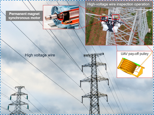
The above research also provides some ideas for this paper, but the difference is that this paper analyzes the working conditions and harmonic suppression methods of permanent magnet synchronous motors in high-voltage wire inspection robots from the perspective of control algorithms (Figure 1). In the research process, the direct torque control of space vector pulse width modulation is analyzed by establishing the mathematical model of the permanent magnet synchronous motor. At the same time, the direct torque control method of the permanent magnet synchronous motor based on time-varying flux amplitude and the harmonic characteristics of the permanent magnet synchronous motor are compared and analyzed.
2 Mathematical Model of Permanent Magnet Synchronous Motor
Under the power supply state of a permanent magnet synchronous motor, the rotational motion and energy exchange process of the internal air gap magnetic field are very complicated, so a simplified mathematical model is established to analyze and calculate. There are three mathematical expression models of the permanent magnet synchronous motor, namely the ABC three-phase stationary coordinate system model, the dq rotating coordinate system model, and the αβ two-phase stationary coordinate system model. When using the static α β coordinate system to build the mathematical expression of the motor, there are few actual parameters needed and only the resistance value of each phase winding needs to be known. At the same time, only one coordinate transformation is needed in the implementation of the control algorithm. The dq rotating coordinate system takes the motor rotor shaft as the stationary reference frame to rotate synchronously, and the direction of the d-axis is the same as the direction of the permanent magnet flux F. If it rotates, the q-axis is 90° ahead of the d-axis. Then the motor rotates in the forward direction, and two coordinate transformations are required during the implementation of the control algorithm. To facilitate the subsequent analysis of the harmonic characteristics of the permanent magnet synchronous motor, and the DTC algorithm used in the following sections does not produce the cumulative error caused by integral deviation when estimating the flux value, the mathematical model of the permanent magnet synchronous motor in the dq coordinate system is adopted in this study.
In Equations (1-3–1-3), Ld, id, and Ψd are d-axis inductance, current, and flux linkage; Lq, iq, and Ψq are q-axis inductance, current, and flux linkage; Ψf is the flux linkage of the permanent magnet; ud and uq are the voltage components of the stator voltage on the d-axis and q-axis in the dq coordinate system; Rs is the stator resistance; w is the spatial rotational speed; np is the number of motor pole pairs; Te is the electromagnetic torque, and TL is the load torque acting on the output of the motor.
It can be seen from Equation (7) that the voltage matrix is equal to the current matrix multiplied by a matrix K in the dq coordinate system, and the Fourier transform is carried out on the left and right sides of Equation (7), respectively. In the dq rotating coordinate system, the harmonic distribution law of currents id and iq is the same as that of voltages Ud and Uq, and the amplitude is related to the matrix K. Because there are reactive components such as resistors and inductors in each phase winding of the motor, the energy of high-frequency harmonics will be weakened, so the amplitude of harmonics at the fundamental wave in the voltage spectrum is much larger than that at other harmonic frequencies.
3 Direct Torque Control Based on Space Vector Pulse Width Modulation
3.1 SVM-DTC Control Principle
According to the analysis in the second part, two hysteresis comparators are introduced into the traditional DTC algorithm of permanent magnet synchronous motor. The output results of the torque loop and flux loop are used as the input values of the switch table to determine the change trend of stator flux at each moment. The torque value in control is obtained by the regulator after speed comparison. Based on the traditional DTC algorithm, the SVM-DTC algorithm combined with SVPWM technology has developed rapidly, as shown in Figure 2.
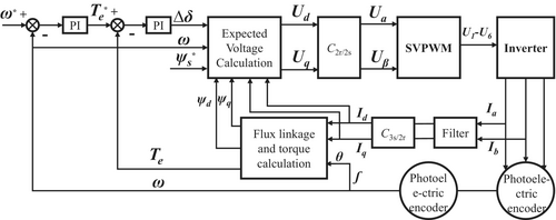
According to the analysis in the second part, the set flux value command Ψs(*) and the obtained Δδ command in the flux loop are directly used as two input parameters of the expected voltage module in the control algorithm, and are used to calculate the straight axis voltage Ud and the cross axis voltage Uq. The direct axis voltage Ud and the cross axis voltage Uq are coordinate transformed to obtain the input signals Uα and Uβ of the SVPWM technology, and the SVPWM is controlled to generate six control signals of the inverter to drive the motor to rotate. Meanwhile, the torque estimate and flux estimate for feedback are calculated in the dq coordinate system. To weaken the high-frequency harmonics of the current, the collected current is low-pass filtered and used to calculate the torque in closed-loop control, thus avoiding the influence of the high-frequency harmonics of the current on the speed signal.
3.2 Space Vector Pulse Width Modulation Principle
Assuming that the names of the three phases of the inverter module are phase A, phase B, and phase C, respectively, different switching combinations of each phase IGBT will generate different voltage vector signals. Taking phase A as an example, sa = 1 represents that the IGBT of the upper bridge arm of phase A is in an on state, while the IGBT of the lower bridge arm of phase A is in an off state. sa = 0 represents that the IGBT of the upper bridge arm of phase A is in an off state, and the other two are the same. Using a three-phase inverter, each phase contains two IGBT switches and can generate a total of 23 = 8 voltage vectors. The three-phase switching mode and voltage vector expression are summarized, and the results are shown in Table 1.
| sasbsc | A phase | B phase | C phase | Vector expression | Vector symbols |
|---|---|---|---|---|---|
| 000 | 0 | 0 | 0 | 0 | u0 |
| 001 | u1 | ||||
| 010 | u2 | ||||
| 011 | u3 | ||||
| 100 | u4 | ||||
| 101 | u5 | ||||
| 110 | u6 | ||||
| 111 | 0 | 0 | 0 | 0 | u7 |
Meanwhile, the eight basic voltage vectors in Table 1 divide the two-dimensional planar space into six fan-shaped regions of equal area, with u0 and u7 at the center point, as shown in Figure 3. After adopting the SVPWM method, according to the space sector number where the stator voltage vector us is located in each sampling period, the basic voltage vectors at both ends of the sector are selected for synthesis, and the allocated time of each voltage vector is calculated according to the volt-second balance formula. Meanwhile, the switching sequence in a sampling period is adjusted by selecting an appropriate zero vector and action time.
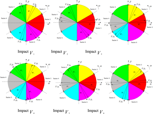
To reduce the switching times of the power tube IGBT and improve the usage efficiency, only one IGBT in a certain phase is selected to change the state for each switching action. The selection sequence of six sector switches is shown in Table 2. The start state of each sector switch in the table is (000), the intermediate state is (111), and the end state is (000).
| u* Sector | Synthetic vector | Transformation process of switching state(sasbsc) |
|---|---|---|
| I | u4, u6 | 000-100-110-111-110-100-000 |
| II | u2, u6 | 000-010-110-111-110-010-000 |
| III | u2, u3 | 000-010-011-111-011-010-000 |
| IV | u1, u3 | 000-001-011-111-011-001-000 |
| V | u1, u5 | 000-001-101-111-101-001-000 |
| VI | u4, u5 | 000-100-101-111-101-100-000 |
- * Represents the actual value.
There are a total of seven states from the beginning to the end, so according to the seven-segment method, the time signal of the IBGT state change is compared with the carrier signal to obtain the switching state of the IGBT in each phase within one sampling period. The SVM-DTC model is built in Matlab/simulink. During the simulation, the rated speed of the permanent magnet synchronous motor is 1500 rpm, the rated voltage is 220 V, the rated power is 3000 W, and the number of pole pairs is 4 pairs. Other parameters are shown in Table 3.
| Parameter | Parameter values | Parameter | Parameter values |
|---|---|---|---|
| Rated voltage | 220 V | Straight axis inductance | 7.187e−3H |
| Rated rotational speed | 1500 rpm | Cross-axis inductance | 7.187e−3H |
| Rated power | 3000 W | Permanent magnet flux linkage | 0.1825 Wb |
| Number of pole pairs | 4 | Stator resistance | 0.8813 Ω |
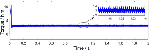
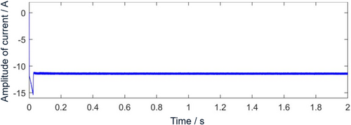
Run the simulation model, set the load torque to 3 Nm, and set the motor speed to 1500 rpm. The simulation duration is set to 2 s, the solver step size is 1 ms, and the carrier frequency is 10,000 Hz. To simulate the actual situation, the dead time is set to 6 ms, the tube voltage drop of the diode is 1 V, and the tube voltage drop of the IGBT is 1 V. The simulation results are shown in Figures 4-6.
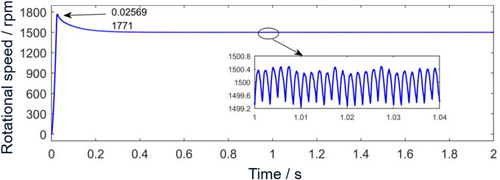
In Figure 4, the overshoot of the starting speed reaches the maximum value at 0.02569 s, which is 1771 rpm.
Subsequently began to decrease, the steady state reached at about 0.45 s. When stable, the speed range is 1499.2 to 1500.8 rpm, and the fluctuation amount is 0.8 rpm, which is small. It can be seen from the time domain diagram of electromagnetic torque in Figure 5 that the electromagnetic torque signal in the stable stage fluctuates around the given value of 3 Nm, and the fluctuation amount is 0.4 Nm, which is small. At the same time, the periodic fluctuation of high-frequency components can be clearly seen. In Figure 6, the d-axis current fluctuates up and down −11.39 A.
To sum up, the simulation results prove the correctness of the SVM-DTC model built in this section. The core target quantity of this control strategy is torque angle. SVPWM is applied to DTC, and two adjacent vectors are selected to represent the voltage vector each time in the control, which avoids the excessive deflection angle of the voltage signal in one sampling period, so the signal fluctuation of the motor speed time domain is small.
4 Direct Torque Control Method of Permanent Magnet Synchronous Motor Based on Time-Varying Flux Linkage Amplitude
For Equation (8), the cross-axis inductance Lq, the rotor flux linkage Ψf and the number of pole pairs np are all constant values, so the flux linkage amplitude with time is only related to the change of torque value in the observer. Therefore, on the basis of SVM-DTC, the improved control strategy flowchart is shown in Figure 7.
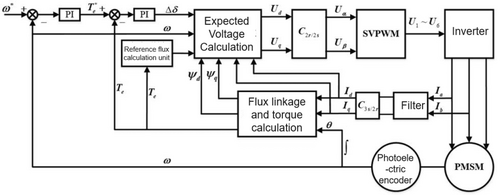
Compared with the SVM-DTC schematic diagram of Figure 2, the difference is that the flux linkage given value unit is replaced by the reference flux linkage calculation unit. The control flow is as follows: the three-phase current signal is collected by the current sensor, and the straight-axis current id and cross-axis current iq in the dq coordinate system are obtained through Clarke transform and Park transform. Together with the collected rotation angle signal, the calculated torque estimate is taken as the input of the time-varying flux amplitude and the feedback value of the torque loop, respectively. Then, the expected voltage module is used to calculate the voltage components ud and uq in dq coordinates, and then the voltage vectors Uα and Uβ are obtained by inverse Park transform and used as the input signals of the SVPWM module, so as to generate six output switching signals and control the inverter to invert the DC voltage into AC power supply to rotate.
The improved control strategy model in Figure 7 is established in Matlab/Simulink. To compare the difference between the simulation results before and after the improvement of the control strategy, the simulation parameters are kept consistent with the previous simulation parameters. Specific parameters of the motor are shown in Table 3.
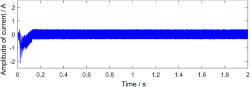
Running the simulation model, Figure 8 is the time domain diagram of the d-axis current of the motor after improving DTC, and the waveform of the d-axis current id fluctuates around 0. In the control algorithm, to get the flux value with respect to time change, the d-axis current has been set to 0. The simulation results show that the d-axis current id is indeed adjusted to 0 in the improved motor algorithm, and the algorithm is correct.
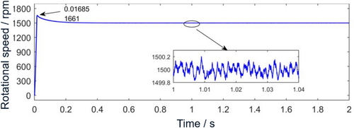
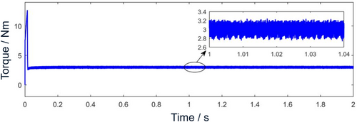
In the time domain diagram of motor speed in Figure 9, after improving the motor control strategy, the motor speed reaches the maximum overshoot at 0.01685, which is 1661 rpm, and reaches a stable state at 0.38 s. Compared with SVM-DTC, the overshoot is reduced by 110 rpm, and at the same time, the response to reach a stable set speed value is faster. When stable, the rotational speed fluctuation range is reduced to 1499.8–1500.2 rpm. The electromagnetic torque fluctuation in Figure 10 is about 0.2 Nm, which is 42.86% lower than that of SVM-DTC. This is because the efficiency is improved, the stator current magnitude is reduced, and thus the current harmonics are reduced.
5 Harmonic Characteristics of Permanent Magnet Synchronous Motor
For Equation (9), the saddle wave waveform can be obtained by adding two waveforms: sine wave Yt and triangular wave Yt. The Fourier series expansion of the phase voltage is equal to the algebraic sum of the Fourier series expansions of the two waveforms.
5.1 Comparative Analysis of Harmonics Before and After Control Strategy Improvement
The permanent magnet on the internal rotating shaft of the motor will generate a rotating magnetic field, and the winding will also generate a rotating magnetic field after being energized. The two are coupled with each other and generate electromagnetic torque. Its function is to drive the motor to rotate. Excessive fluctuation of electromagnetic torque will lead to a large fluctuation in speed, causing torsional vibration of the transmission shaft system, which seriously affects the NVH performance of inspection robots and even the service life of the motor. Therefore, it is necessary to analyze the spectrum of speed signals and torque signals of permanent magnet synchronous motors.
To analyze the change trend of harmonic characteristics of rotational speed before and after the improvement of the control strategy in this article, the rotational speed signal under the SVM-DTC method in the third part and the rotational speed signal under the improved DTC method in the fourth part are subjected to fast Fourier transform, and the harmonic characteristics near the low-frequency band and double carrier are compared and analyzed. The simulation conditions in Figure 9 are load torque 3 Nm, motor speed 1500 rpm, carrier frequency set to 10,000 Hz, and solution step set to 1 ms. The simulation time is 2 s, and 100 cycles of data are selected for Fourier transform starting from 1 s. The sampling frequency is 106 Hz and the frequency resolution is 1 Hz. To reduce the energy leakage of harmonic components, Hanning window is selected as the window function of truncated data during the whole cycle sampling.
Figure 11 is a spectrum diagram of the rotational speed before and after improvement of the control strategy. It can be seen from the figure that the main harmonic components such as 0, 600, 1200, 1800, and 2400 Hz appear at low frequencies under the improved SVM-DTC method, where the amplitude at 0 Hz is 1500 rpm, which is the given motor speed value. Because the motor speed set in the simulation is 1500 rpm, the fundamental frequency of the motor shaft and rotor frequency is 25 Hz, and because the number of motor pole pairs used in the simulation is 4 pairs of poles, the current fundamental frequency is 25 × 4 = 100 Hz, and the harmonic components appearing at low frequency correspond to 6 times, 12 times, 18 times, and 24 times the current fundamental frequency respectively. These frequency components are caused by factors such as inverter dead time, which is consistent with the theoretical results.
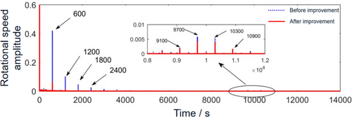
At high frequency, harmonic components of 9100, 9700, 10,300, and 10,900 Hz mainly appear near the carrier wave, corresponding to 3 times the current modulation frequency and 9 times the current modulation frequency near the switching frequency of 10,000 Hz, respectively. These frequency components are caused by the SVPWM technology used in the control, because after using SVPWM technology, the phase current harmonics generate modulation frequencies of even times the current fundamental frequency, such as 2, 4, 8, and 10 times the current fundamental frequency near the carrier wave fc, and will become 3 times the current fundamental frequency and 9 times the current fundamental frequency when transformed into the dq coordinate system.
After using the improved control algorithm in this paper, the harmonic components such as 600, 1200, and 1800 Hz caused by 0 Hz and dead time also appear in the low-frequency band of the motor speed spectrum, and the harmonic amplitude at 0 Hz is 1500 rpm. The amplitudes of other harmonic components are so small that they can be ignored. The harmonic components of 9100, 9700, 10,300, and 10,900 Hz near the carrier also appear in the high-frequency band. Further observing the change trend of the amplitude of the speed spectrum, taking the first harmonic 600 Hz as an example in the low-frequency band, the amplitude at 600 Hz is 0.42 under the driving of SVM-DTC, but after using the improved control algorithm in this study, the amplitude at 600 Hz is reduced to 0.006259, and the amplitude is reduced by 85.1%. Compared with SVM-DTC, the amplitude reduction effect is very significant, and the amplitude at other main 6 k times current harmonics is also effectively reduced. For high frequency, taking the first-order modulation frequency of 9700 Hz as an example, the amplitude at 9700 Hz under SVM-DTC driving is 0.005795, and the amplitude at 9700 Hz after improvement is 0.004054, which is reduced by 30.04%. To better analyze the effect of reducing the amplitude of main harmonics, the amplitude and change rate of the main harmonic components of the speed before and after the improvement are shown in Table 4.
| Analytical formula | Harmonic order | SVM-DTC | Improved SVM-DTC | Amplitude reduction rate |
|---|---|---|---|---|
| 6 fs | 6 times current fundamental frequency | 0.42 | 0.006259 | 85.1% |
| 12 fs | 12 times current fundamental frequency | 0.1022 | 0.01042 | 89.8% |
| 18 fs | 18 times current fundamental frequency | 0.0467 | 0.003493 | 92.52% |
| fc-9 fs | First-order switching frequency side frequency | 0.002007 | 0.001711 | 14.74% |
| fc-3 fs | First-order switching frequency side frequency | 0.005795 | 0.004054 | 30.04% |
| fc + 3 fs | First-order switching frequency side frequency | 0.005417 | 0.003853 | 28.87% |
| fc + 9 fs | First-order switching frequency side frequency | 0.001626 | 0.001498 | 7.8% |
In Table 4, the suppression effect of main harmonics in the middle- and low-frequency bands is better than that in the high-frequency bands. Among them, the reduction rate of harmonic amplitude in low-frequency band is above 85%, and the reduction effect is very obvious. The decrease rate is the largest at 18 times the current fundamental frequency, reaching 92.52%. Although the suppression effect of harmonics in high-frequency band is not as obvious as that in low-frequency band, it is also reduced to some extent. The maximum reduction rate of amplitude reaches 30.04% at 9700 Hz, and the minimum reduction rate is 7.8% at 10,900 Hz. Further observation shows that the amplitude of harmonic components in the low-frequency band is two orders of magnitude different from that in the high-frequency band. To sum up, the improved control algorithm has a very obvious suppression effect on motor speed harmonics in the analysis frequency band.
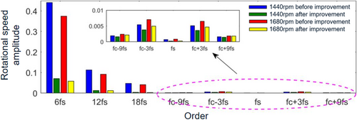
To better illustrate the correctness and universality of the improved effect, the simulation conditions are changed. The rotating speed is 1440 and 1680 rpm, respectively, the corresponding current fundamental frequency is 96 and 112 Hz, the load torque is set to 3 Nm, and the other simulation conditions remain unchanged. The comparison of the rotating speed spectrum is shown in Figure 12. After the improved control method, the amplitude of main harmonics at low frequency and high frequency of rotational speed is obviously reduced, and the simulation results verify the universality of the proposed method.
5.2 Analysis of Dynamic Response Characteristics
Dynamic response performance is the most basic performance requirement of the motor, which mainly includes two aspects: one is the ability of the motor speed to track the set target speed when the speed command suddenly changes, and the other is the ability of the motor speed to restore to the set speed value after the load torque command is changed. Therefore, while suppressing the fluctuation of motor speed and harmonic amplitude, it is also necessary to ensure that the dynamic response performance of new energy electric vehicles does not decline or is even better.
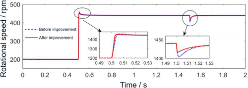
To analyze the dynamic response characteristics of the target motor before and after the improvement of the control algorithm, step speed signal and step load torque signal are applied to the motor under two different control strategies, and the response speed of the speed signal when the working condition suddenly changes is compared and analyzed. The specific simulation conditions are as follows: given the initial target speed of 1200 rpm, it rises after 0.5 s and suddenly changes to 1440 rpm. Given an initial load torque of 3 Nm, the torque suddenly changes to 6 Nm after 1.5 s.
Compare the time domain diagrams of rotational speed under the two control methods in one figure, as shown in Figure 13. From the speed time domain, it can be seen that under the two sudden conditions of variable speed and variable torque, the overshoot of the improved motor speed is smaller, the stabilization time after the sudden speed change is shorter, and the ability to recover to the given speed is better. The above simulation results prove that the improved motor control strategy can not only reduce the amplitude of motor harmonic components but also further improve the dynamic response performance of new energy vehicles.
5.3 Experimental Validation
Design the hardware system, software system, and data acquisition system, and build the required motor towing test system. The system structure is shown in Figure 14.
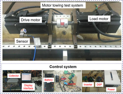
In Figure 14, the two motors are placed opposite each other. The two motor shafts are connected by an elastic coupling with a shaft diameter of 14 mm in the middle. The motor is installed horizontally and mounted on the clamping tool, and the installation tool is fixed on the support. An acceleration sensor is mounted on the drive motor. The drive motor is powered by a 60 V regulated power supply, and the load motor is powered by a 60 V battery.
First, the correctness of the improved time-varying flux amplitude DTC based on SVM-DTC in this paper is verified by using the built drag system. In the algorithm, the target rotational speed of the driving motor is set to 1440 rpm. The running speed of the DSP controller reaches 150 M, the switching frequency is set to 9375 Hz, the dead time is set to 6 ms, and the load torque is set to 0.2 Nm in the load motor control algorithm. Taking the rotation speed of 1440 rpm as the experimental condition, the experimental results are shown in Figure 15.
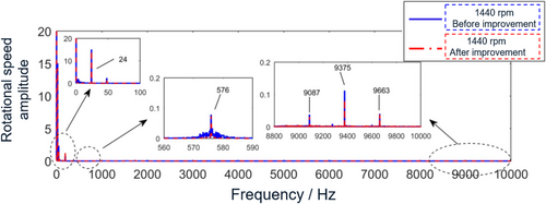
Figure 15 is a comparison chart of the current spectrum. When the speed is 1440 rpm, the current fundamental frequency is equal to 96 Hz, and the four frequency components of 480, 672, 1056, and 1248 Hz in the low-frequency band correspond to 5, 7, 11, and 13 times of the current fundamental frequency, respectively. At the high frequency, there are mainly modulation side bands of 9759, 9567, 9471, 9279, 9183, and 8991 Hz, which correspond to 1, 2, and 4 times the current frequency.
6 Conclusion
- In this article, starting from the mathematical model of the permanent magnet synchronous motor, the SVM-DTC simulation model is established in Simulink, and the d-axis and q-axis voltage components are calculated by expected voltage. Considering that the electromagnetic torque is only related to the q-axis current i_q, and the d-axis current is equal to zero in the adjustment control algorithm, a direct torque control method of the permanent magnet synchronous motor based on time-varying flux linkage amplitude space vector modulation is proposed on the basis of SVM-DTC, which is very simple to implement. The vibration characteristics of the motor before and after the improvement of the control strategy are compared and analyzed. Compared with SVM-DTC, the amplitude of the d-axis current i_d before the improvement is 11.39 A, and the amplitude of the d-axis current i_d after the improvement is zero. The improvement of the control strategy has achieved results. At the same time, after the improved motor control strategy, the torque fluctuation of the motor decreased by 42.86%.
- The voltage harmonic components caused by SVPWM are analyzed, mainly the modulation frequencies of current fundamental frequency and even multiples of current fundamental frequency such as 2 times and 4 times near 1 time switching frequency. The addition of dead time will cause harmonic components of current fundamental frequency such as 5th, 7th, 11th, and 13th voltages. These frequency components are converted to dq rotating coordinate system and become harmonics of 6k times current fundamental frequency. The distribution law of current harmonics is consistent with the voltage.
- The spectrum diagrams of the speed signals before and after the improvement of the control strategy are compared and analyzed. Under the improved control strategy, the amplitude suppression effect of 6k times the current fundamental frequency harmonics and the main harmonics near 1 times the switching frequency in the low-frequency band is obvious. The harmonic suppression effect in the low-frequency band is better than that in the high-frequency band, and the amplitude reduction rate reaches 92.52% at 18 times the current fundamental frequency. Using two working conditions of variable torque and variable speed, it is proved that the dynamic response performance of the motor is further improved under the improved control strategy. Finally, the effectiveness of this method is verified by experiments.
Author Contributions
Ma Long: conceptualization, writing – original draft. Xu Xiaoyi: methodology. Mao Yanfang: software. Wang Baocang: data curation.
Conflicts of Interest
The authors declare no conflicts of interest.
Open Research
Data Availability Statement
The data that support the findings of this study are available from the corresponding author upon reasonable request.


