Enhanced Stability and Performance of Islanded DC Microgrid Systems Using Optimized Fractional Order Controller and Advanced Energy Management
ABSTRACT
The increasing demand for electrical power is placing heavy pressure on the power system transmission network. To reduce this burden and conversion losses, a distributed generation-based DC microgrid system is favorable due to its flexibility and reliability. However, traditional control approaches for the power grid are impractical for islanded microgrids, making stability a primary concern. Using a conventional PI controller results in significant deviations in DC bus voltage and prolonged settling times. Additionally, conventional techniques fail to ensure adequate current sharing between the battery and supercapacitor, which are employed to control the DC bus voltage. To address these issues, this study proposes the use of an optimized fractional order PI (FOPI) controller and an efficient energy management algorithm. The FOPI controller regulates processes while meeting constraints, with the control rule generated from minimizing a cost function. A complete mathematical model of the DC microgrid is developed along with the proposed controller to facilitate detailed analyses. The developed energy management system (EMS) ensures energy balance within the microgrid with regulated DC bus voltage and state-of-charge (SoC) limits. Comparing the performance of the FOPI controller with that of the conventional PI controller reveals significant improvements: the DC bus voltage deviation is reduced by 63.63%, and the settling time is 16.67% faster during PV variation. During load variation, the maximum DC bus voltage deviation is 2.25 V, and the settling time is 202 ms, which are within acceptable ranges.
1 Introduction
Due to increasing heavy load demand, the pressure on centralized power generation based on fossil fuels is rising daily. However, fossil fuel resources are depleting and have adverse environmental effects. Renewable energy (RE)-based distributed generation (DG) has garnered significant attention, mitigating environmental issues and addressing increased load demand. Additionally, establishing new transmission lines is often restricted due to regional political issues and other complications. Hence, microgrids offer a strong alternative to long-distance transmission by enabling remote generation and providing more efficient operations due to their DG characteristics. DC microgrids, in particular, have several advantages over AC microgrids, including the integration of photovoltaic power generation without inverters, direct connection to DC loads, and the elimination of reactive power and frequency control issues [1, 2]. The DC microgrid employs a DC bus on which distributed energy resources (DERs) such as photovoltaic (PV) arrays and wind energy are interfaced to the DC bus via power electronic converters, while energy storage systems (ESS) such as batteries and supercapacitors (SCs) are interfaced to the DC bus via bidirectional boost converters for supplying power to the DC load illustrated in Figure 1. However, several control issues like uncertainty, complex control, and fault ride-through capability have been included due to RE integration. The DC microgrid gives greater flexibility to integrate distributed resources [3, 4]. Control of DG and ESS has mainly focused on two objectives, i.e., bus voltage control and load power sharing [5]. The first objective targets the reduction of deviation in steady state conditions, and the latter one manages power sharing among DGs depending on their capability and availability [6]. Decentralized droop control is the most used technique to achieve these control goals. Due to the involvement of line parameters, there is a tradeoff between the two using traditional droop control [7]. Again, poor selection of droop control parameters may be accountable for improper power sharing and DC bus voltage deviations.
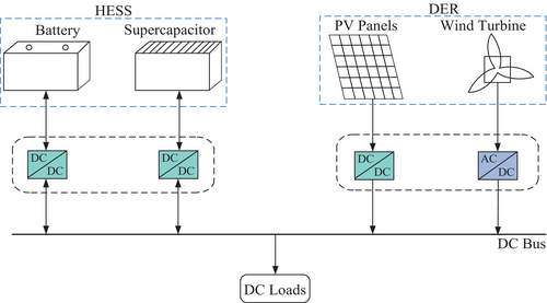
Incorporating low bandwidth links in a centralized controller is offered in much literature [8, 9]. It is noteworthy to mention that because of the uneven and uncertain nature of RE resources (RERs), incorporating ESSs including batteries and SC increases the reliability of the supply system [10]. Therefore, having the independence of PV availability to enable efficient multisource integration with reduced components and enhanced power management, a novel five-port nonisolated DC–DC converter for DCMG was proposed [11]. Although the modified droop controller [12] improves power-sharing in hybrid ESS systems, precise power-sharing is not attained. Virtual resistance and virtual impedance droop controllers [13] also contribute to the progress made in power-sharing. Using a dual active bridge (DAB) converter with a simple single-loop control strategy, a new converter categorization approach [14] for DC microgrids into bus voltage controlled converters (BVCC), bus current controlled converters (BCCC), and indirect bus impedance converters (IBIC) was introduced, and the development enhanced small-signal stability and impedance emulation without requiring high-bandwidth control or internal plant modeling and development of a hardware-based active stabilizer. An additional power-sharing strategy is proposed in reference [15] for a SC and hybrid battery system to enhance the DC bus voltage deviation. Nevertheless, this methodology employs a traditional proportional integral (PI) controller and necessitates the exchange of bus voltage information between the SC and the battery. Typically, impedance droop controllers are applied to heterogeneous ESS devices [16, 17] whereas virtual resistance droop controllers are utilized for homogeneous ESS devices. A coupled technique of virtual resistance and capacitive droop is implemented [17] so that various ESS devices can generate loads with distinct frequency components. Again, to control the DC line voltage in a hybrid AC–DC microgrid, Senapati proposed the TS-fuzzy controller, which excels over the Mamdani controller in a dynamic voltage profile [18].
There are issues with rapid DC charging in electric vehicles (EVs), such as low inertia, voltage instability, and power fluctuations. To tackle these challenges, a hybrid Firefly Algorithm-Particle Swarm Optimization (FA-PSO) was proposed to adjust Takagi-Sugeno Fuzzy Inference Systems (TSFIS), Adaptive Neuro-Fuzzy Inference Systems (ANFIS), and Fractional Order Proportional-Integral-Derivative (FO-PID) controllers [19]. The Ragone plot [20] shows that the fuel cell (FC) has the maximal amount of energy density compared to the battery energy storage system (BESS), capacitor, and SC. By dynamically modifying the gains of the PI controllers in the battery energy storage system (BES), Takagi-Sugeno fuzzy logic [21] was utilized to enhance DC-link voltage response under transient circumstances. To maintain stable voltage while addressing the challenges posed by nonaffine system dynamics, constant power loads, and variations in solar irradiation and load demand, a nonlinear control strategy was introduced for voltage regulation and MPPT in DC microgrids with PV generation and battery storage [22]. The longevity of the battery will be shortened, though. Hence, a battery and SC combination called a hybrid energy storage system (HESS) taking advantage of both high energy and power density has been extensively used. To figure out the relative merits and demerits of the battery and supercapacitor on several control configurations is described in [23]. Furthermore, to enhance power distribution and reduce stress on the battery by leveraging the fast response by SC, a SC voltage-based power sharing and energy management strategy for hybrid energy storage systems was developed [24]. The high-frequency current elements of the battery were redirected to the supercapacitor, leading to an enhanced battery life. A power coordination control strategy between the RERs and ESS comprising of PV, wind, battery, and SC incorporating both DC and AC bus was proposed in [11]. The issue of current sharing between HESS was not properly mentioned. For proper management and control strategy, PV systems with batteries and supercapacitors were proposed [25]. However, it lacks transparency of battery SC current control for managing variable power control. To address this power management issue, a composite converter for HESS [26] was proposed. The stated composite converter mainly focused on obtaining balance in the SoC of energy storage and used a switching technique based on a hysteresis control strategy. Again, to improve MPPT tracking performance, especially in the presence of partial shade conditions (PSCs) and rapid climate swings, a hybrid algorithm was formulated [27]. In [28], a multimode fuzzy logic energy allocator approach was introduced in the PV system with HESS to mitigate the disparities between demand-generation variation. Furthermore, the implementation of multimode fuzzy logic is complex. Based on the power management strategy, Hredzak et al. [29] proposed model predictive control to maintain the SoC of the battery and supercapacitor within specified limits. Because of the centering of predictive regulation of HESS, this method includes a more complex mathematical calculation. Through sensitivity analysis, Kotra and Mishra [30] discovered that traditional charge controllers could cause ringing in DC bus voltage, potentially leading to instability, and suggested an optimal controller based on experimental studies. Kollimalla et al. [31] suggested a PI control-based strategy for managing power distribution between batteries and supercapacitors to address the mismatch between demand and generation. However, these methods have several shortcomings, such as their response to sudden changes in power demand, the PI controller's failure to fully mitigate the effects of uncertainties, and the intermittent nature of RE sources (RES). To fix these issues, a new distributed control, i.e., a sliding mode control strategy [32, 33] was developed for buck power converter and current sharing in DCMG. However, under dynamic load conditions, it is not possible to eliminate current sharing error on every microgrid unit. Roy et al. [34] introduced a nonlinear backstepping control method for the operation of islanded DC microgrids that enhances power distribution among DC microgrid elements to balance demand and generation, maintains state of SoC within limits, and regulates DC bus voltage. However, they did not take into account scenarios involving fluctuations in sources and loads, which can escalate battery stress and consequently decrease battery lifespan. Using small signal stability analysis of DC microgrid, Singh and Lather [35] proposed the application of FCs for mitigating power surges at slow frequency and SCs for mitigating power surges at faster frequency. But it has a less robust response because of lacking a higher degree of freedom using a conventional PI Controller. Based on real time digital simulator (RTDS) simulation, Alam et al. [36] proposed a fractional order controller which gives higher robustness against disturbances and uncertainties in microgrids. But practical variation of DG including noise source and MATLAB simulation was absent here.
However, these strategies commonly overlook critical issues such as current sharing and the rapid regulation of DC bus voltage within permissible limits during source and load variations. Additionally, the performance of these systems is limited by the sluggish dynamic response of power converters and the overcharge/discharge rates of batteries, which are not adequately addressed in current management approaches. Furthermore, there is a lack of optimized control techniques that can effectively maintain voltage stability and power balance in DC microgrids, especially under varying and noisy conditions typical of RES like solar PV.
The increasing integration of RES into islanded DC microgrid systems presents significant challenges related to voltage stability, power sharing, and efficient energy management. Conventional PI controllers often fail to mitigate these issues due to their limited adaptability and response time. Existing energy management strategies also lack robustness in handling dynamic variations in load and generation. To address these shortcomings, this study proposes an optimized fractional order PI (FOPI) controller integrated with an advanced energy management system (EMS). The proposed method aims to enhance system stability, improve transient response, and achieve efficient power distribution among the DC microgrid components. The system employs a novel fractional order voltage compensation technique in the outer voltage control loop and inner current control loops of both the battery and SC, enhancing voltage regulation and power-sharing capabilities. The Particle Swarm Optimization (PSO) algorithm is applied to minimize the integral time absolute error (ITAE), optimizing the performance of the DC microgrid model. The incorporation of an optimized fractional order PI controller and EMS ensures voltage stability and power balance within the microgrid while automatically controlling the SoC of the battery and SC, thereby extending the battery's lifespan. The proposed approach is validated through MATLAB/SIMULINK simulations under varying conditions, including PV and load variations with noise, demonstrating effective power sharing and rigid DC voltage regulation with minimal transient effects. Additionally, small-signal stability analysis confirms the stable operation of the microgrid under different conditions. These contributions provide a robust and efficient control strategy for DC microgrids, addressing the limitations of current HESS management strategies and enhancing overall system performance.
- Development of an optimized fractional order PI (FOPI) controller to enhance system stability.
- Proposal of an advanced EMS to improve power sharing.
- Integrated approach combining optimized control and EMS for improved transient response and voltage stability.
The rest of the article is structured as follows: Section 2 demonstrates the DCMG control strategy, Section 3 demonstrates mathematical modeling of components and fractional calculus, Section 4 demonstrates PSO optimized FOPI controller and small signal modeling, Section 5 demonstrates simulation results and comparison between conventional and proposed method during source and load variation, and finally, Section 6 concludes with the contributions and findings.
2 DCMG System Configuration and Control Strategy
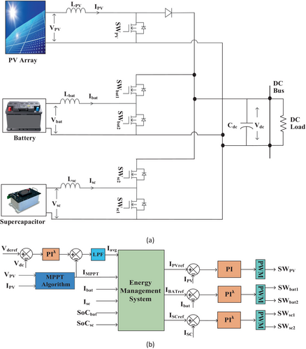
An autonomous DCMG consists of a PV array, a DC load, and HESS, which is shown in Figure 2a. Due to intermittency and an uncertain nature, the generated power does not match the load power. A battery with higher energy density and a SC with higher power density are used as HESS. The PV array is interfaced with the DC bus with a DC–DC boost converter, whereas the battery and SC are connected with a bidirectional DC–DC converter.
2.1 Proposed Control Scheme for Smooth Power Transition
In the proposed control scheme shown in Figure 2b, the DC bus voltage is compared to a predetermined reference voltage. The outer voltage loop controller generates a current reference based on the difference between the reference voltage (Vref) and the actual DC voltage (Vdc).
The MPPT current is then compared with this reference to determine whether the system has excess or insufficient power. Based on load demand, the EMS generates current references for the PV, battery, and SC to either share power efficiently or absorb excess power.
To ensure a smooth transition between the SC and battery during power fluctuations, a coordinated control strategy is implemented. The SC quickly responds to transient power demands due to its fast charge–discharge characteristics, while the battery supplies long-term energy to maintain system stability. The transition between these energy storage elements is carefully managed to prevent abrupt power surges, thereby reducing stress on the battery and enhancing its lifespan. The fractional-order PI controller-based energy management algorithm, illustrated in Figure 3, is used to stabilize the DC bus voltage when a mismatch between the PV source and load variations occurs. It generates reference signals for the PV, battery, and SC to maintain optimal power flow. The EMS operates in different modes based on power availability and load demand:
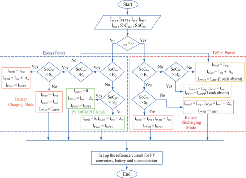
- Excess Power Mode: If the PV generation current (Iavg) exceeds the reference current, the EMS directs excess power to the battery if its state of charge (SoC) is within the predefined limits. If the battery SoC exceeds its upper limit, PV operates in Off-MPPT mode to avoid overcharging.
- Deficit Power Mode: When PV generation is insufficient, the EMS prioritizes power distribution from the battery and SC based on their SoC levels, ensuring a continuous power supply to the load.
The EMS ensures smooth power transitions by dynamically adjusting the contribution of the SC and battery based on system conditions. This prevents sudden voltage fluctuations and ensures stable DC bus voltage regulation.
- To recognize the operating condition of the DCMG based on average current (Iavg).
- To maintain power balance during demand-generation mismatches.
- To enable seamless power transitions between the battery and SC, improving system efficiency and reliability.
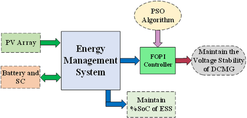
The system architecture represented in Figure 4 is an EMS for a DC Microgrid, integrating a PV array and an energy storage system (ESS) with a battery and SC for efficient energy utilization. The EMS optimizes power distribution while maintaining the SoC of ESS and ensuring voltage stability. A FOPI controller, optimized using PSO, dynamically adjusts control parameters to regulate system stability.
3 Mathematical Model of Components
3.1 Modeling of PV
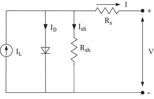
The fundamental component of the PV system is the solar cell, which converts light energy into electrical energy. The equivalent circuit of the solar cell consists of a current source, a p-n junction diode (D), a shunt resistor due to inhomogeneity of the surface and loss of current at the solar cell edges (Rsh), and a series resistor due to the silicon bulk resistance and material contact (Rs).
3.2 Modeling of Battery
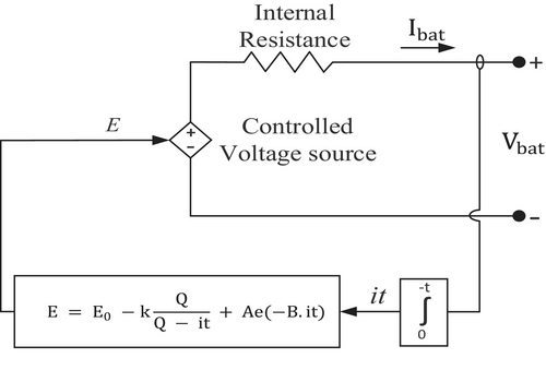
A battery with a straightforward regulated voltage source and continuous durability is built in series in Figure 6. Rapid charging and discharging shorten battery life. Thus, it needs to be charged and discharged carefully and within the SoC limit.
3.3 Modeling of SC
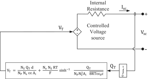
A distinct SC model is presented to characterize SC electrical properties [39]. Figure 7 depicts the SC equivalent circuit. These equations are used to determine the output voltage of the SC.
3.4 Introduction of Fractional Calculus
Several definitions of fractional differ-integral are given. Three widely recognized definitions of them include the Riemann-Liouville, Caputo, and Grunwald-Letnikov definitions.
3.4.1 Fractional Order PI Controller
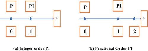
Understanding the concepts of conventional integer order PI control and FOPI control can be facilitated by observing the graphical representation on the λ axis. The integer order controller is characterized by two fixed points on the λ axis. In contrast, the fractional order PI controller is depicted as a continuum of points spanning from 0 to 2, as illustrated in Figure 8. Consequently, it provides a higher level of flexibility and adaptability compared to the conventional integer order controller.
4 PSO Optimized FOPI Controller and Small Signal Modeling
4.1 Description of the Cost Function
ITAE is used as the cost function.
4.2 Solution Approach With PSO
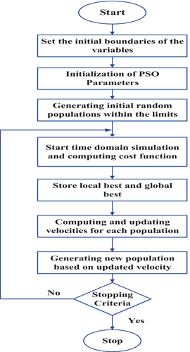
The minimization problem described by Equation (19) is solved by modified particle swarm optimization (MPSO). The well-known heuristic approach, MPSO, is utilized to optimize the parameters of the suggested fractional-order voltage controller. The social phenomena of bird flocking serve as the foundation for our heuristic algorithm. A collection of randomly generated particles is used to search the search space while the MPSO algorithm is running, with the goal of reducing the cost function. MPSO has numerous benefits, including precise outcomes through a straightforward procedure, rapid convergence, and suitability for online optimization [43]. The MPSO algorithm represents the velocity and position vectors in space using the following equations [43].
The overall flowchart for the MPSO to design the fractional order PI is shown in Figure 9.
4.3 Small Signal Model of DCMG
The small signal model is used to assess the stability of a DC microgrid when subjected to minor disturbances in the vicinity of its operating point. Ensuring the microgrid's ability to maintain stable voltage and power flows is of the highest priority, particularly in the presence of small disruptions such as load shifts, line failures, or variations in power supply, as Figure 10 illustrates the DCMG small signal model of DCMG. where Vdc is the measured voltage and Vdcref is the reference voltage of the DC bus. Gf(s) is the transfer function of the low pass filter having a cutoff frequency of 5 Hz.

4.3.1 Design of Current Control Loop
4.3.2 Design of Voltage Control Loop
4.3.3 Parameter Measurement and Stability Analysis
4.3.4 Small Signal Stability Analysis
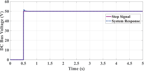
By applying a step signal input, the response of the system is shown in Figure 11. From the response of the system, it is evident that the output signal follows the input signal with a small overshoot, which is within the permissible limit (±5% per IEEE std. 519–1992) at the step change of the input.
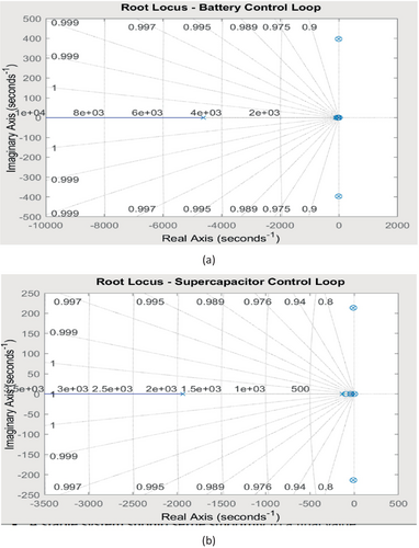
The root locus and Bode plots illustrate the stability and dynamic characteristics of the battery and SC closed-loop systems. From Figure 12a, the battery control loop's root locus shows a dominant pole at −4.6255 × 10³, indicating a fast response and high stability. The complex conjugate poles at −9.5 × 100 ± 397.2i suggest oscillatory behavior, while additional real poles at −108.8, −19.4, and 0.0 contribute to the system's transient and steady-state response. Again from Figure 12b, the SC closed-loop system, on the other hand, has a dominant pole at −1.9368 × 10³, which implies a relatively slower response compared to the battery system. The complex poles at −9.5 × 100 ± 213.9i also introduce oscillations, but they are more damped than those in the battery system.
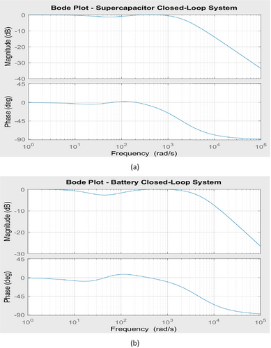
The Bode magnitude plots for both systems illustrating in Figure 13a show a gradual roll-off at higher frequencies, ensuring effective attenuation of disturbances, while the phase plots illustrating in Figure 13b reveal phase lag, particularly at high frequencies. The battery system exhibits a quicker response but is more prone to oscillations due to the higher imaginary component of its poles, whereas the SC system is more damped, leading to smoother transient behavior. Both systems remain stable as all poles have negative real parts, but fine-tuning the controller parameters may be necessary to optimize performance by balancing damping and response time.
5 Simulation Results and Discussion
The studied DCMG illustrated in Figure 2 is simulated in a MATLAB/SIMULINK environment. The PSO-optimized parameters of the FOPI controller, including proportional (Kp), integral (Ki), and fractional order (λ) values, are detailed in Table 1. The component ratings of DCMG are presented in Table 2. The PSO algorithm parameters, including population size, number of iterations, and cognitive and social coefficients, are listed in Table 3. The simulation was conducted using MATLAB Simulink version 2020a. The sampling time was set to 1e-6 s, which was selected to ensure the precision and accuracy of the numerical solution over the period of interest. The ODE23 solver was employed to find the numerical solution of the differential equations, a second-order Runge–Kutta method with an adaptive step size. The proposed FOPI controller and EMS are being implemented in three case scenarios:
Case I.Variation in PV generation
Case II.Change in load demand
Case III.Simultaneous Variation of PV generation and Load demand
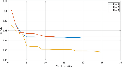
Using the PSO optimization algorithm depicted in Figure 9, the controller parameters were iteratively tuned to minimize the cost function described in Equation (19). This tuning process was conducted across three runs to ensure optimal performance. The convergence behavior of the cost function is illustrated in Figure 14, where the curve corresponding to the run for three time demonstrates a lower ITAE value compared to the other runs, indicating superior performance. The optimized controller parameters obtained from three individual runs are detailed in Table 2.
| Controller | KP | Values | Ki | Values | λ | Values |
|---|---|---|---|---|---|---|
| Outer voltage controller | KP1 | 1.92 | Ki1 | 219.962 | λ1 | 1.1850 |
| Battery current controller | KP2 | 2.00 | Ki2 | 109.042 | λ2 | 1.2569 |
| SC current controller | KP3 | 1.32 | Ki3 | 126.487 | λ3 | 0.1309 |
| Parameters | Specifications |
|---|---|
| PV Array @ STC | VOC = 22.1 V, isc = 7.8 A, vm = 17.6 V, imax = 6.8 A |
| Battery | 12 V, 14 Ah |
| Supercapacitor | 29 F, 32 V (2 Nos. connected in series) |
| DC–DC converter | LPV = 11.4 mH, Lsc = 1.8 mH, Lbat = 1.2 mH, Cdc = 440 μF |
| DC load | R = 20 Ω |
| Parameters | Value used |
|---|---|
| Population size | 50 |
| No of iteration | 30 |
| Cognitive coefficient, c1 | 2.05 |
| Social coefficient, c2 | 2.05 |
5.1 Case-I Variation in PV Generation
Due to the intermittent behavior of light energy incident on the earth, the PV power generation is impossible to keep at a fixed level. The variation in solar irradiance is used for the model in which noise is added to mimic real-world phenomena.
In this instance, fluctuations in PV power occur at the 1, 2, 3, and 4 s intervals, taken as indicative, due to changes in solar irradiance, which consequently impact the output voltage in proportion to the PV power. Between the 2 and 3 s intervals, the PV power falls below the load demand. During this time interval, the load demand is still at 125 W, depicted in Figure 15a, while PV generation stands at 118.5 W. Consequently, a combination of PV power and ESS (battery and SC) is supplied to meet the load demand. The power sharing is managed by the EMS. At the steady state period, power is supplied by a battery, and during the transient period, SC provides the required power. This is because the response time of the battery is slower than that of SC. During the deficit PV generation interval, the battery and SC discharge power to maintain the DC bus voltage constant. At the time intervals 1 s to 2, 3 to 4 s, and 4 to 5 s, PV power generation is higher than the load demand. During these intervals, the load demand is only supplied by the PV power. Therefore, the battery and SC are in charging mode.
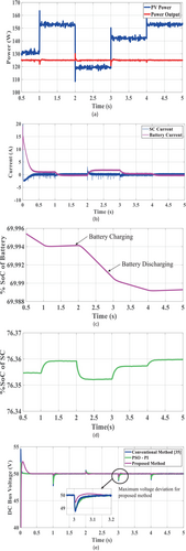
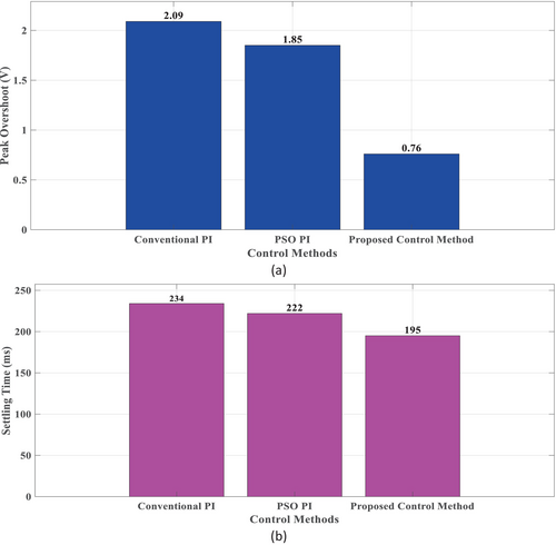
Additionally, at this moment in time, the supercapacitor has successfully managed the high-frequency component and is progressively transferring the low-frequency component of the current to the battery, as illustrated in Figure 15b. As evidenced by Figure 15e, the EMS facilitates faster and more precise regulation of the DC bus voltage, with an approximate deviation of ±0.76 V, meeting the permissible range of ±5%. This regulation is achieved with minimal voltage overshoot, settling time, and a modest battery charging rate, consequently minimizing dynamic stress on the battery. According to current sharing between SC and battery to mitigate voltage deviation, Figure 15c,d illustrate the waveform of changing the %SoC in battery and SC. Table 4 describes the comparison among conventional and proposed control methods.
| Response | Transient parameters | Conventional control method [35] | PSO PI | Proposed control method |
|---|---|---|---|---|
| DC bus voltage | Peak overshoot/undershoot (MP) | 2.09 V | 1.85 V | 0.76 V |
| Settling time (tss) | 234 ms | 222 ms | 195 ms |
5.2 Case II: Change in Load Demand
In real-world circumstances, load demands vary throughout time, resulting in the DC bus voltage fluctuating. To ensure the safe operation of the electric equipment connected to the DC bus, the DC bus voltage must be regulated within a prescribed range. As a result, we examined the stability of our suggested technique against variations in load demand. The load resistance ranges from 20 to 11 Ω. Because of load variations, electricity demand fluctuates accordingly.
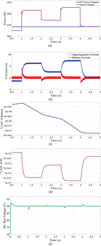
When the load resistance is reduced from 20 to 11.6, the power demand increases from 0 to 1 s. The load resistance increased compared to the preceding phase between 2 and 3 s. As a result, the power demand falls. The phenomena are represented in Figure 16a. The PV generation remains constant, while the power consumption fluctuates due to load variations. Excess or deficit power sharing between the battery and supercapacitor is performed by injecting or absorbing current into or from the DC bus, as seen in Figure 16b. Because the battery responds slowly, the supercapacitor provides peak power at the point of load fluctuation. The EMS regulates the DC bus in excess or deficiency of power. During deficit power mode, the battery and supercapacitor provide the necessary power to stabilize the DC bus voltage, as shown in Figure 16b. When the load demand falls below the PV generation, the battery and supercapacitor store energy. During the interval 0–1 s, the DC bus operates in surplus power mode, increasing the SoC of both the battery and the SC. For the rest of the experiment, the DC bus operates in deficit power mode. As a result, the SoC of the battery and supercapacitor drop concurrently, as seen in Figure 16c,d. The DC bus voltage is maintained at the desired level by efficiently distributing current among the solar array, battery, and supercapacitor. Figure 16e depicts the DC bus voltage as the load varies. In compliance with IEEE Standard 519–1992, the bus voltage is managed within a ±5% range of the immediate load fluctuation.
5.3 Case III: Simultaneous Variation of PV Generation and Load Demand
This section evaluates the proposed control strategy's robustness against simultaneous PV generation and load demand variations, crucial for real-world DC microgrid operation. Figure 17 illustrates a representative test case. Figure 17a shows fluctuating PV power (150–110 W) and corresponding load power variations. Despite these changes, the DC bus voltage featuring in Figure 17e remains stable around 50 V, with deviations of 2%–6%, well within acceptable limits. This demonstrates effective voltage regulation. Figure 17b shows the coordinated battery and SC current response. Decreased PV and load power leads to battery discharge and SC energy absorption. Conversely, increased PV and load power prompts SC discharge and increased battery charging, demonstrating smooth energy management. The battery SOC representing in Figure 17c and SC SOC representing in Figure 17d reflect these charging/discharging patterns. This coordinated control ensures rapid settling time and minimal overshoot/undershoot in the DC bus voltage, maintaining system stability under dynamic conditions. The results validate the proposed strategy's effectiveness in real-world scenarios with simultaneous PV and load fluctuations, ensuring reliable DC microgrid operation.
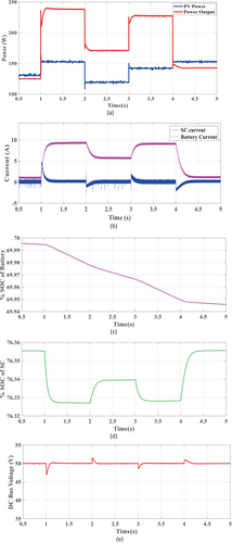
The graphical representation of the comparative analysis among conventional PI, PSO PI control method, and proposed control method is presented in Figure 18a,b. The findings show that the proposed control method regulates the dc bus voltage more quickly and accurately and also has less settling time than those conventional methods used previously.
6 Conclusion
This study aimed to improve the stability, reduce steady-state error, mitigate overshoot, and enhance the settling time of islanded DC microgrid systems. The conventional PI controller was found insufficient in achieving these performance goals. To address these shortcomings, a PSO-based Fractional Order PI (FOPI) controller and a novel EMS algorithm were proposed. The integration of the FOPI controller and EMS algorithm significantly enhanced the system's response speed and reduced transient DC bus voltage deviations. During PV variation, the proposed FOPI controller-based system achieved a DC bus voltage deviation of 0.76 V, which is 63.63% lower than that of the conventional PI controller, and settled in 195 ms, 16.67% faster than the conventional approach. Figure 15a illustrates the peak overshoot comparison, revealing a substantial reduction with the proposed method compared to the conventional PI and PSO-optimized PI controllers. Figure 15b further highlights the improved settling time of the proposed method relative to the conventional PI and PSO-optimized PI controllers. In the case of load variation, the system maintained a maximum DC bus voltage deviation of 2.25 V, settling within 202 ms. Additionally, the EMS effectively managed the SoC of the battery and supercapacitor, enhancing efficiency and extending their lifecycles. Considering simultaneous PV generation (150–110 W) and load changes, the proposed control technique effectively maintains DC bus voltage stability around 50 V, with deviations of around 2%–6%. The battery and supercapacitor (SC) work together flawlessly to ensure smooth energy balancing by absorbing or delivering power as required and again the battery and SC's having SoC variations reveal their dynamic reactivity, allowing for quick correction for power fluctuations. These results demonstrate that the proposed EMS-based controller outperforms conventional controllers in maintaining system stability and performance. The approach supports the efficient integration of RE with DC microgrids, contributing to the achievement of sustainable development goals. Future research will focus on optimizing the EMS algorithm for various RES and enhancing the adaptive capabilities of the proposed controller under diverse operational conditions. While the proposed method has demonstrated promising results in MATLAB/Simulink simulations, real-time implementation remains an area for future exploration. Hardware-in-the-loop (HIL) testing and full-scale experimental validation will be pursued in future work to further establish its practical effectiveness.
Nomenclature
-
- BDDC
-
- bidirectional DC–DC converter
-
- BESS
-
- battery energy storage system
-
- BL
-
- battery lower limit
-
- BU
-
- battery upper limit
-
- CCL
-
- current control loop
-
- DCMG
-
- DC microgrid
-
- EMS
-
- energy management system
-
- Hbat
-
- battery current sensor feedback gain
-
- HESS
-
- hybrid energy storage system
-
- HIL
-
- hardware in loop
-
- Hsc
-
- supercapacitor current sensor feedback gain
-
- Iavg
-
- average current
-
- ibat
-
- battery current
-
- ibatref
-
- battery reference current
-
- iL
-
- inductor current
-
- imppt
-
- maximum power point tracking current
-
- iosc
-
- net sum of oscillating current
-
- ipv
-
- photovoltaic current
-
- ipvref
-
- photovoltaic reference current
-
- isc
-
- supercapacitor current
-
- iscref
-
- supercapacitor reference current
-
- Ki_bat
-
- integral gain of battery
-
- Ki_sc
-
- integral gain of supercapacitor
-
- Kp_bat
-
- proportional gain of battery
-
- Kp_sc
-
- proportional gain of supercapacitor
-
- L
-
- inductance
-
- MPPT
-
- maximum power point tracking
-
- PMS
-
- power management system
-
- SC
-
- supercapacitor
-
- SoC
-
- state of charge
-
- SoCbat
-
- SoC of battery
-
- SoCsc
-
- SoC of supercapacitor
-
- TF
-
- transfer function
-
- VCL
-
- voltage control loop
Author Contributions
Md. Wahidujjaman: methodology, software, formal analysis, writing – original draft, conceptualization. Tasnim Ul Bari: conceptualization, methodology, software, formal analysis, writing – original draft. Md. Shafiul Alam: conceptualization, writing – review and editing, formal analysis, resources. Md. Rashidul Islam: writing – review and editing, methodology, validation, supervision. Md. Alamgir Hossain: writing – review and editing, validation. Md. Rafiqul Islam Sheikh: validation, writing – review and editing, supervision.
Conflicts of Interest
The authors declare no conflicts of interest.
Open Research
Data Availability Statement
The data that support the findings of this study are available from the corresponding author upon reasonable request.


