Numerical Study on the Influence of Web Corrugation Geometry on Cyclic Performance of Link Beams in Eccentric Braced Frames
ABSTRACT
This investigation delves into the essential role of link beams within eccentric braced frames, serving as the key structural element responsible for withstanding the lateral drifts induced by earthquakes, even when subjected to substantial deformation. Due to lack of a wide comparative assessment on the influential variables on the cyclic response parameters and equivalent damping of the link beams with corrugated webs, a comprehensive parametric study was conducted in this investigation. To do so, a selection of 18 distinct case studies has been meticulously curated to consider several influential variables. These include the shape of corrugations, which could be trapezoidal or have a curved web plate, the specific angles at which the corrugated web plate is configured, as well as the number of angles or curvatures present in the web plate. To facilitate a thorough analysis, finite element micro models have been developed and subjected to both monotonic and cyclic shear loading conditions. The outcomes of these analyses reveal a notable improvement in the capacity for rotation and the efficient dissipation of energy as the angles and the number of angles in the corrugated web plates increase. Furthermore, the models with 90-degree corrugation (T-90) demonstrate ductility levels that are either on par with or surpass the benchmark model, as evidenced by ductility factors ranging from 12.34 to 17.85, compared to the F model's factor of 12.62. In addition, the T-90 models exhibit an enhanced cyclic response, as indicated by their higher overstrength Factor (Ω0) values, which range from 1.36 to 1.41. These findings affirm the superior performance of the T-90 models compared to the F model. Remarkably, one of the case studies featuring a 90-degree web corrugation displays a higher ultimate capacity and a greater capacity for energy dissipation, all while using 4.5% less steel. This highlights the cost-effectiveness of implementing optimized corrugated link beams in structural designs.
1 Introduction
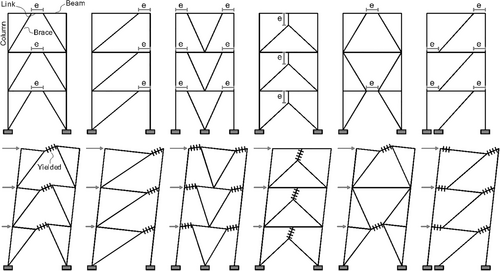
Eccentrically braced frames (EBFs) present a unique combination of advantageous characteristics, merging the ductility features of moment-resisting frames with the lateral stiffness observed in concentrically braced frames [1-4]. Due to high ductility and geometrical adaptability of the link beams in EBFs various formats and configurations have been studied by engineers [5-9]. Various configurations of the EBF system are depicted in Figure 1. The seismic stability of EBFs relies heavily on the appropriate behavior of the link beam, given the constraints imposed on the buckling of braces. As a crucial structural element acting as a fuse, the link beam significantly influences the overall behavior of EBFs, confining nonlinear behavior specifically to itself, while expecting other frame members to behave within the elastic range. The link beams are generally categorized into three distinct classes based on their yielding mechanisms: short, intermediate, and long link beams. Short link beams, referred to as shear link beams, effectively dissipate energy through shear yielding of the web. A comparative analysis between short and long link beams reveals the superior seismic responses of short link beams in terms of elastic lateral stiffness, ductility, energy dissipation, and ultimate strength. The length reduction of link beams can lead to a substantial increase in the demand for plastic rotation, thus necessitating careful consideration in structural design. The AISC seismic code [10] addresses this concern by imposing a maximum plastic rotation limit of 0.08 radians for shear link beams. These findings enhance our comprehension of the dynamic performance of the structures with EBFs and offer valuable insights for optimizing link beam behavior during design considerations [11]. I-shaped and box link beams have gained widespread adoption in EBFs as critical structural components. While I-shaped link beams necessitate the insertion of lateral braces at both ends to counteract lateral torsional buckling arising from their relatively low torsional stiffness, box link beams offer an alternative solution. The absence of lateral braces in box link beams is contingent upon the moment of inertia around the weak axis, surpassing 67% of the moment of inertia around the strong axis. This feature renders box link beams preferable in scenarios where the provision of lateral braces poses challenges, such as bridge structures or the space between elevator cores. Extensive numerical and experimental investigations have been conducted to examine the behavior of I-shaped link beams. These studies have contributed to a comprehensive understanding of their structural performance under various loading conditions. An effective yet efficient solution is incorporation of corrugated web in I shaped beams. Hence, further research is warranted to explore the design considerations, performance characteristics, and advantages associated with corrugated link beams, as their application in EBFs presents a promising alternative in situations where lateral braces are difficult to utilize [12, 13].
The utilization of steel beams with corrugated webs has witnessed a notable surge within the construction industry in recent years. A significant proportion of these beams typically feature thin trapezoidal corrugated webs welded to flanges composed of thick plates. Although the prevailing preference for trapezoidal-shaped corrugations remains unclear, it is likely attributed to their comparatively simpler manufacturing process in comparison to curved-shaped corrugations. A crucial design aspect pertaining to beams with corrugated webs is the assumption that the longitudinal stiffness of the corrugated web is negligible. Consequently, the design moment capacity is solely derived from the flanges, while the shear capacity relies on the shear strength of the web. An important advantage associated with beams incorporating corrugated webs is the enhanced elastic shear buckling stress when compared to beams featuring flat webs. This study highlights the significance of considering beams with corrugated webs in structural design due to their distinct advantages, ultimately contributing to improved performance and efficiency in steel beam applications [14, 15]. Corrugated plates, produced through a simple and cost-effective cold rolling process, have a long-standing history as one of the oldest forms of steel. The introduction of waves in various shapes significantly enhances the out-of-plane stiffness of thin plates. Moreover, the fold line in corrugated plates exhibits relatively high stiffness, akin to transverse stiffeners, which enhances their buckling capacity. By altering the plate's geometry, the geometrical properties of corrugated plates transform from isotropic to orthotropic, thereby enabling the creation of greater strength while consuming fewer materials. Corrugated plates possess inherent characteristics such as low weight, high strength, suitable out-of-plane stiffness, ease of use, simple construction, and obviation of intermediate stiffeners. These attributes make corrugated plates an advantageous choice in steel construction projects [15]. Elgaaly et al. [16] conducted comprehensive experiments and numerical studies on I-shaped beams incorporating corrugated webs, aiming to understand the failure modes and buckling behavior exhibited by the corrugated plate. Their findings indicate that the failure mode of the corrugated plate can be categorized as either global or local buckling. Specifically, when the wavelengths of the corrugations are relatively large, local buckling dominates the behavior of the corrugated web. In contrast, when the waves are densely packed and possess shorter wavelengths, global buckling becomes the primary mode of behavior for the corrugated web [17].
Based on the findings of a study by Fanaie and Pesaran [18], the utilization of low yield point steel with a compactness ratio below 16.5 and the absence of intermediate stiffeners as a link web, can effectively prevent the occurrence of local shear buckling. Additionally, the incorporation of low yield point steel in a link beam may result in an increased response modification factor. In another study by Hajimirsadeghi and Fanaie [19], an examination was conducted to explore the possibility of eliminating intermediate stiffeners in a box link beam by incorporating two distinct types of low yield point steel, manufactured in Japan and China, into the web of the box link beam. The investigation utilized finite element modeling within the Abaqus software. The study's findings indicate that when low yield point steel is used in a link beam without the need for intermediate stiffeners, the maximum allowable compactness ratio for the link web can be increased by up to 56% compared to the maximum compactness ratio typically prescribed for conventional structural steels. In another research conducted by Mohammadzade [20], the primary objective was to explore and enhance the efficiency of energy absorption and dissipation mechanisms within steel moment frames characterized by short span lengths and deep beams. A key challenge in designing steel moment frame systems lies in adhering to specific code restrictions, including minimum span length and beam depth requirements, which are imposed to facilitate the formation of plastic hinges at both ends of the beams. However, by introducing a modification that weakens a section of the beam's midpoint, the energy dissipation mechanism transitions from bending to shear, effectively mitigating this issue. Such a proposal literally turns the mid-section of the moment frame beam into a link beam.
In the context of box link beams, the common practice involves the use of intermediate stiffeners to delay the onset of local shear buckling [21]. However, the welding process required to connect these intermediate stiffeners to the web of box link beams results in a series of drawbacks, including elevated construction expenses, reduced construction speed, the generation of residual stresses, the introduction of geometric imperfections, and a weakening of the materials at the juncture of the stiffeners and the web. As examined by researchers [21], an alternative approach for box link beams by investigating the utilization of corrugated webs instead of flat webs with intermediate stiffeners. The research employed Abaqus finite element software for analysis. Initially, equations were developed to determine the slenderness ratio and the critical inelastic buckling stress of trapezoidal corrugated plates when employed as the web component of box link beams. A comparison between box link beams with corrugated webs and those with flat webs and intermediate stiffeners revealed that box link beams featuring corrugated webs exhibited superior buckling stability, ductility, and energy dissipation. These advantages were attributed to the inherent geometric characteristics of the corrugated web plates.
Theoretical analysis reveals that local buckling primarily occurs within a flat subpanel, whereas global buckling involves multiple sub-panels and extends diagonally across the entire depth of the web. Elgaaly et al. further suggest that when the critical stress for local or global elastic buckling exceeds 80% of the material's shear yield stress, the buckling phenomenon of the plate transitions into an inelastic state. These findings contribute to our understanding of the buckling behavior and failure modes in I-shaped beams with corrugated webs, providing valuable insights into the design and analysis of such structural elements [17]. Previous studies have classified the buckling failure modes of beams with corrugated webs into three distinct shear buckling modes: local shear buckling, global shear buckling, and interactive shear buckling. These modes are illustrated in Figure 2. Local shear buckling pertains to a single flat panel, while global shear buckling involves multiple panels with buckles that extend diagonally across the entire height of the web. Interactive shear buckling, on the other hand, occurs due to the interaction between local and global shear buckling and involves a few panels [22].

Driver et al. [23] conducted a study investigating the shear strength characteristics of I-shaped beams featuring corrugated webs. They identified several key factors influencing shear strength, including web depth, plate thickness, wave geometry, material properties, and initial geometric imperfections. The researchers highlighted that the corrugated web is unable to withstand axial stresses, leading to an accordion effect. Consequently, it can be assumed that the flanges bear the entire bending moment in the beam, and the interaction between shear and flexure can be disregarded. Through experimental investigations, Driver et al. observed a failure mode that combines the previously mentioned local and global buckling modes, which they referred to as the interactive buckling mode. These findings contribute to a deeper understanding of the shear strength, axial stresses, and failure modes in I-shaped beams with corrugated webs, enabling more accurate analyses and design considerations for such structural elements [23]. In another study, Driver et al. [10] conducted an investigation examining the influence of the longitudinal to diagonal subpanel width ratio on the cost-effectiveness and critical stress of global buckling in I-shaped beams. Their findings revealed that a low ratio of longitudinal to diagonal subpanel widths results in a design that is not cost-effective. Conversely, a higher ratio reduces the critical stress associated with global buckling. According to Abbas's recommendation [24], the optimal range for this parameter should fall between 1 and 2. Sayed-Ahmed [25] conducted research highlighting the advantages of utilizing a corrugated web in structural design. The incorporation of a corrugated web allows for a reduction in the required thickness of the web plates and eliminates the need for welds associated with stiffeners. This design modification results in a lighter and more cost-effective solution. Moreover, Sayed-Ahmed presented an equation to calculate the critical interactive buckling stress specifically for trapezoidal and zigzag corrugated webs [25]. Yi et al. [26] conducted a comprehensive investigation utilizing the finite element method to study the behavior of corrugated webs in I-shaped beams. Through their analysis, the researchers observed that shear buckling failure within the corrugated web often displays characteristics associated with both global and local buckling modes, resulting in an interactive buckling phenomenon. Additionally, Yi et al. presented mathematical relationships that facilitate the determination of the critical buckling stress for I-shaped beams incorporating a corrugated web [26]. El Metwally and Loov [27] conducted a study focusing on beams featuring corrugated webs and prestressed concrete flanges. Their research identified several advantages associated with the use of corrugated webs in these beams, including: (1) a reduction in the stress required to prestress the flanges, attributed to the accordion effect of the corrugated plate; (2) the potential for increased beam length due to the reduction in dead load; and (3) an appropriate stress distribution between the flanges and webs, allowing the flanges to primarily bear bending stresses while the webs handle shear stresses. Additionally, the researchers presented a mathematical relationship to determine the shear capacity of trapezoidal corrugated webs. Jáger et al. [28] conducted an experimental research program focusing on the lateral-torsional buckling strength of trapezoidal corrugated web girders. Through their experimental study, the researchers made noteworthy observations and derived those imperfections have key role in the LTB behavior. Specifically, for girders with compact flanges, the failure mode was determined to be purely lateral-torsional buckling. Conversely, in the case of girders featuring slender flanges, a coupling between flange buckling failure and lateral-torsional buckling failure was observed. These findings contribute to our understanding of the behavior of trapezoidal corrugated web girders, particularly in terms of lateral-torsional buckling strength [28]. Liu et al. [15] investigated involving three curved box girders with corrugated steel webs (CSWs). The study found that the shear strain distributions in CSWs of horizontally curved girders (HCGs) are nearly uniform along the web height direction, similar to CSWs in straight girders. The principal strain direction angles were found to be close to 45°. The tests revealed that CSWs were responsible for carrying approximately 76% of the shear force in the specimens. Additionally, during the destructive test, shear buckling occurred after yielding in all specimens, which aligns well with theoretical predictions. This suggests that the analytical formulas employed offer accurate estimations for the shear buckling stress of CSWs in HCGs and can be recommended for design purposes [29]. In another study conducted by Wang et al., the researchers investigated the shear failure mechanism of large-scale CSWs) primarily affected by local buckling in bridge girders. They performed shear tests on three beams with standard large-scale CSWs and conducted corresponding nonlinear finite element analyses. The study aimed to understand the failure mode, typical load-deflection curve, out-of-plane deformation, and strain distribution. Additionally, the researchers analyzed the influence of initial imperfections on shear behaviors in detail. The findings revealed that the shear failure of large-scale CSWs, dominated by local buckling, involved the elastoplastic buckling of two adjacent sub-panels due to fold interactions, exhibiting characteristics of snap-through instability. The shear loading process was categorized into four stages: elastic stage, elastoplastic stage, buckling stage, and post-buckling stage [30]. Nikoomanesh and Goudarzi conducted a study on the ultimate patch loading capacity (UPLC) of sinusoidal corrugated web beams (SCWBs). They performed experimental tests on 15 girders and developed a numerical model using nonlinear finite element analysis to simulate the behavior of SCWBs under patch loadings. The validity of the numerical model was confirmed by comparing its results with experimental measurements. A comprehensive parametric study was then conducted, involving 120 cases, to examine the effects of various parameters. A failure mechanism for SCWBs, assuming local elastoplastic buckling of the corrugated web, was established, and an analytical solution for UPLC was proposed. The accuracy of the analytical solution was confirmed through finite element results of SCWBs with different dimensions and experimental measurements. This analytical solution can be recommended for estimating the UPLC of SCWBs with different wave dimensions and load widths [31]. In a numerical study conducted by Riahi et al. [17], the authors investigated I-shaped beams with different web configurations, including flat, trapezoidal, sinusoidal, and zigzag webs. Their findings revealed that the shear strength of the corrugated web was approximately 1.5 to 2 times higher than that of a flat plate web without stiffeners, with both webs having the same thickness. The researchers also observed that increasing the flange thickness did not have a substantial impact on the buckling strength of the corrugated plate. However, it did contribute to enhancing the beam's overall stiffness [32]. In recent times, there has been a global focus on reducing the weight of bridge superstructures and optimizing construction processes to minimize labor and costs. One approach to achieve this goal is the implementation of tapered steel plate girders with corrugated webs (TPGCWs), which feature non-prismatic profiles with varying depths. To explore the shear behavior of TPGCWs utilizing high-strength steels (HSSs), a parametric study was conducted. The study resulted in the development of a novel equation that accurately estimates the ultimate shear strength of TPGCWs. This study significantly advances engineering knowledge and facilitates the effective integration of HSSs, commonly used in diverse applications, with TPGCWs due to their favorable esthetic and structural attributes [33]. The findings obtained from the nonlinear finite element analysis revealed that the shear stress reaches its peak value and is uniformly distributed across the web until the occurrence of buckling. Subsequently, the shear stress decreases, leading to an uneven distribution, while the enhanced tensile stress becomes the primary contributor to resistance. Additionally, it was observed that stocky corrugated webs attain shear yield strength. Comparisons conducted between established analytical models used to estimate shear strength and experimental test data demonstrated that EN-1993-1-5 is both accurate and sufficiently conservative for economical design purposes [34, 35]. Continuing their research in this field, the authors conducted imperfection sensitivity studies and made significant findings. By incorporating an initial geometric imperfection based on the first eigen buckling mode, with a maximum amplitude of amax/200 (where amax represents the maximum corrugation fold length), the estimated ultimate strength closely matched the test results within a 3% margin. However, when the amplitude was increased to hw/200 (where hw denotes the web height), the average estimated ultimate strength was found to be 25% lower than the experimental results. Notably, for three of the investigated girders, initial imperfections with different forms than the first buckling mode were identified as more critical. Furthermore, regardless of the mode number, it was observed that mode shapes extending further over the web panel led to a higher degradation of the ultimate shear strength [36]. To investigate the flexural capacity and limit state of vertical flange buckling in corrugated web beams with slender webs commonly found in industrial buildings, full-scale tests were conducted Lho et al., in 2015. The experimental study aimed to assess the flexural behavior of these beams and the influence of residual stress. All specimens exhibited failure due to vertical flange buckling following flange yielding at the mid-span. Based on the test results, a modified slenderness ratio limit was proposed, set at 1.5 times the conventional value. Numerical analysis incorporating various parameters was performed to validate the accuracy of the modified slenderness ratio limit [37]. Abbas conducted studies on I-shaped beams with corrugated webs, revealing that such beams undergo in-plane deformations and out-of-plane torsion when subjected to in-plane moment and shear. The out-of-plane torsion can be conceptualized as a transverse flange moment. This transverse moment in the flange of the I-shaped beam, combined with the axial stresses generated by in-plane bending, arises due to shear flow within the web and the eccentricity of this flow with respect to the beam's centerline. To determine the transverse moment in the flange, Abbas introduced a method called the Fictitious Load Method [38]. Sherman and Fisher conducted an investigation on the connectivity between corrugated web and flanges to determine the required level of connection for achieving full yield strength. Through their experimental study, they found that connecting the diagonal panels had a minimal impact on the stiffness and strength of the beam under monotonic loads, particularly when the corrugation wave angle exceeded 45°. They identified two primary types of web-to-flange connection failure: (a) tearing of the web material and (b) failure occurring at the throat of the solder fillet or the fillet bond. When the length of the fillet weld decreases, force concentration can lead to shear-induced tearing of the web along the toe of the fillet [39]. In another investigation, it was observed that specimens of non-welded inclined fold (IF) with or without flange stiffeners experienced web tearing as the primary failure mechanism following web and flange local buckling. Conversely, specimens with continuous welding between the web and flanges exhibited a failure mode characterized by local flange buckling. Additionally, the study compared the experimental results with predictions made by the European Code in terms of flange capacity against local buckling. The findings indicated that the absence of welding in the inclined fold affected the inelastic behavior and capacity of the structurally built-up corrugated webs (SBCWs). Furthermore, the bending resistance equations provided by EN 1993-1-5 were deemed reliable in predicting the test results of the non-welded inclined fold, yielding a high level of safety [34, 40]. In a separate investigation, nonlinear finite element analyses were employed to investigate the influence of various geometric parameters on stress concentrations in corrugated web steel girders and provide insights into experimental findings. Two distinct sources of stress concentration contributing to fatigue cracking were identified and assessed. One source was found to be related to the radius of curvature between the web folds, while the other was associated with the inclination angle of the inclined fold. Additionally, an analytical technique based on fracture mechanics was proposed to enable designers to estimate the fatigue life of corrugated web steel girders. This approach facilitates a better understanding of the effects of geometric parameters and aids in designing girders with improved fatigue resistance [41]. This paper presents a novel investigation into the utilization of corrugated plates as the web material for steel coupling beams, aiming to enhance their seismic behavior. Unlike conventional approaches employing flat webs with stiffeners, this study explores the application of corrugated webs. The research encompasses both linear elastic-buckling analysis and nonlinear analysis of steel coupling beams with flat and corrugated webs, employing finite element techniques. Notably, apart from the benefits of eliminating web stiffeners, the findings reveal that the adoption of corrugated webs, adhering to the proposed geometric criteria, enables the achievement of higher rotation capacity compared to traditional steel coupling beams. The study contributes valuable insights into the seismic performance improvement potential offered by corrugated web designs, highlighting their advantages and potential for enhancing structural response [42]. In a recent innovative investigation, the potential of employing corrugated plates as the web material for steel coupling beams was examined, with the objective of enhancing their seismic behavior. In contrast to conventional practices that utilize flat webs with stiffeners, this study focused on the utilization of corrugated webs. The research encompassed both linear elastic-buckling analysis and nonlinear analysis, utilizing finite element techniques, to evaluate the performance of steel coupling beams with both flat and corrugated webs. Importantly, in addition to the advantages of eliminating web stiffeners, the study demonstrated that the incorporation of corrugated webs, adhering to specific geometric criteria, can result in increased rotation capacity compared to conventional steel coupling beams. The findings contribute valuable insights into the potential improvement in seismic performance offered by corrugated web designs, highlighting their advantages and potential to enhance the structural response [43]. In another study, it was ascertained that the shear buckling strength of steel beams with corrugated webs is a multifaceted phenomenon influenced by a multitude of parameters. The research aimed to construct a mathematical model capable of accurately predicting the shear strength of such beams. To accomplish this objective, a comprehensive data set comprising 93 experimental data points from diverse sources was compiled. Through the utilization of multivariate regression analysis (MRA), mathematical models were developed for the key response parameter, specifically the shear buckling strength of steel beams with corrugated webs. These models accounted for various input parameters encompassing geometric characteristics, loading conditions, and material properties [44].
1.1 Innovation of the Study
Though many aspects of the web corrugated link beams were scrutinized by researchers in the past, little attention was paid to certain influential parameters such as cyclic response parameters of the link beams with a trapezoidal shape and sinusoidal shape corrugated webs. Moreover, to the best of the authors knowledge a wide assessment and a comparative study of the effect of the wave number and wave angle on the response parameters and most importantly the equivalent viscous damping (EVD), has not been carried out before. Such factor is too important to neglect especially due to the nature of the link beams in EBFs and high value of the response modification factor for EBFs. It is deemed essential to conduct such a through comparison regarding the equivalent damping. Hence, the study focuses on three primary geometric types of shear link webs. These include the traditional flat web with stiffeners, a corrugated web with a trapezoidal shape, and a corrugated web with a sinusoidal shape. Additionally, a parametric investigation was conducted, considering the number of waves in the corrugation and different web thicknesses. Finite element models were developed for case studies and subjected to both monotonic and cyclic loadings. Through analysis of the obtained data, relationships were derived and proposed to predict the hysteretic response of the corrugated link beams.
2 Finite Element Modeling
2.1 Verification of Numerical Models
Abaqus software is a widely used finite element software employed for solving various engineering problems. In this particular study, three experimental investigations were selected for verification of finite element simulations to ensure the accuracy of finite element modeling in the Abaqus software. The first experimental study involved a beam with intermediate stiffeners, which was tested by Mansouri and Christopoulos [45]. The second experimental study focused on a beam with a trapezoidal corrugated web subjected to monotonic loading, as tested by Nie et al. [22]. While numerous studies have examined the behavior of I-shaped beams with corrugated webs under monotonic loading, there have been limited experiments conducted to evaluate the cyclic behavior of corrugated webs. Several studies have indicated that the stress distribution in the web of link beams exhibits similarities to the behavior observed in shear wall web plates.
2.1.1 Verification of Flat Link Beam With Stiffener
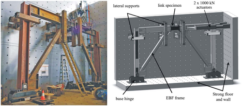
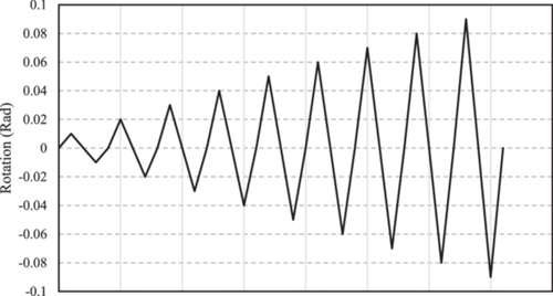
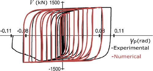
In this section, a validation process is carried out on an I-section link beam that was previously tested and strengthened with web stiffeners in an EBF configuration. The verification study conducted by Mansouri and Christopoulos [45] is utilized for this purpose. The experimental setup used in the reference study is illustrated in Figure 3, and the geometric properties of the specimens used in the validation are provided in Table 1. The specimens in this study were subjected to cyclic loading following the guidelines of AISC 360 [10], as depicted in Figure 4. The developed finite element (FE) model employed solid C3D20R elements, and mesh analysis was performed to ensure accurate and efficient analyses. The hysteresis responses of the finite element model and the experimental specimen are compared in Figure 5. The results demonstrate excellent agreement with a maximum error of 3.2%, thereby confirming the reliability and accuracy of the finite element modeling approach.
| ID | Section | e/(Mp/Vp) | Intermediate stiffeners | Web connection reinforcement plate |
|---|---|---|---|---|
| UT-3A | W360 × 101 | 20 | 3 at 200 mm | None |
2.1.2 Verification of Beam With a Trapezoidal Corrugated
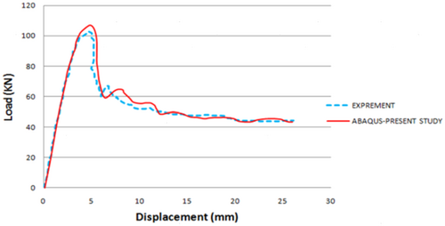
In an investigation conducted by Nie et al. [22] eight H-shaped steel girders were experimented to examine the shear behavior of girders with trapezoidal CSWs. Subsequently, a comprehensive parametric study was performed, employing linear elastic buckling analysis, to establish a simplified formula for determining the elastic shear buckling strength of trapezoidal CSWs, considering three distinct shear buckling modes. To validate the accuracy of the model, this study was selected, and the model's response was meticulously adjusted to align with experimental results. Figure 6 illustrates the geometric properties of the specimen and therefore the developed finite element model. As illustrated in Figures 7 and 8, the numerical results show adequate accuracy with the experimental results.


3 Elimination of Stiffeners Through Corrugated Web
3.1 Research Scope
In this study endeavor, our focus revolved around a comprehensive investigation of three distinct configurations of link beams, aiming to assess their performance. These configurations are comprised of a conventional link beam equipped with web stiffeners, link beam with trapezoidal corrugated web, and link beam with sinusoidal corrugated web. Although a considerable body of research exists within this domain, as evident from the aforementioned literature review, certain aspects have remained unexplored, thus necessitating further exploration. To the best of the authors' knowledge, a comprehensive and simultaneous parametric and comparative study encompassing all three types of link beams has not been previously undertaken. Our research went beyond the typical scope by delving into an array of influential variables, such as shear rupture failure in the link beams, the number of waves present in the corrugated web, and the angle formed by these waves in relation to the longitudinal axis of the beam. Through meticulous investigations, it is sought to shed light on the intricate interplay of these factors and their impact on the structural behavior of link beams. The ultimate result of this investigation includes factors such as overstrength Factor (Ω0), maximum strength, rotation capacity, ductility, energy dissipation, equivalent damping, and failure modes inherent to the link beams. This comprehensive array of findings not only enriches the understanding of each link beam configuration's performance but also furnishes valuable insights that hold paramount significance for the realm of structural design and analysis. As our research concluded, it is evident that the implications of these findings resonate far beyond the immediate confines of this study, stretching into broader domains of structural engineering and its practical applications.
3.2 Finite Element Models
Table 2 showcases the numerical models utilized in this study, along with their respective geometrical properties. The abbreviations employed are defined as follows: “T” denotes trapezoidal webs, “S” stands for sinusoidal webs, and “F” represents flat webs. In the case of trapezoidal configurations, the middle value in the ID indicates the angle formed by the web waves in relation to the beam's longitudinal axis, while the last singular number denotes the number of waves present.
| No. | ID | Wave no. | Angle | Inclined plate length (cm) | Straight plate length (cm) |
|---|---|---|---|---|---|
| 1 | Flat | ||||
| 2 | T-30-2 | 2 | 30° | 16.50 | 16.42 |
| 3 | T-30-3 | 3 | 30° | 11.00 | 10.95 |
| 4 | T-30-4 | 4 | 30° | 8.50 | 7.78 |
| 5 | T-45-2 | 2 | 45° | 17.00 | 20.92 |
| 6 | T-45-3 | 3 | 45° | 12.00 | 13.02 |
| 7 | T-45-4 | 4 | 45° | 9.00 | 9.06 |
| 8 | T-60-2 | 2 | 60° | 14.00 | 31.00 |
| 9 | T-60-3 | 3 | 60° | 14.00 | 16.00 |
| 10 | T-60-4 | 4 | 60° | 11.00 | 11.50 |
| 11 | T-90-3 | 3 | 90° | 12.85 | 30.00 |
| 12 | T-90-4 | 4 | 90° | 12.85 | 22.50 |
| 13 | T-90-5 | 5 | 90° | 12.85 | 18.00 |
| 14 | T-90-6 | 6 | 90° | 12.85 | 15.00 |
| 15 | T-90-7 | 7 | 90° | 12.85 | 12.85 |
| 16 | T-90-8 | 8 | 90° | 11.25 | 11.25 |
| 17 | C2 | 2 Arcs with radius 12.12 | |||
| 18 | C3 | 3 Arcs with radius 12.12 | |||
| 19 | C4 | 4 Arcs with radius 12.12 | |||
3.3 FE Model Definitions and Boundary Conditions
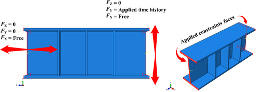
The applied loading point and corresponding restraints are depicted in Figure 9. As evident, on end of the link beam is subjected to monotonic/cyclic loading history, while the other end is free to exhibit horizontal translations. The same material as the verification model of flat link beam with stiffener, i.e., steel with yield strength and ultimate strength of consecutively 420 and 540 MPa were used. Case studies were modeled using C3D8R elements. The Dynamic Explicit package solver was employed.
4 Finite Element Analysis Results
4.1 Monotonic Response Assessment
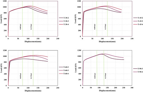
The study investigates the influence of the number of waves in link beams on their monotonic response, as depicted in Figure 10. The results indicate a consistent trend across all cases, where an increase in the number of waves corresponds to an enhanced link beam capacity. According to AISC-360 [10], the ultimate rotation capacity for safe design is 0.08 Rad, while in practice, the real ultimate capacity with plastic hinges forms at approximately 0.15 Rad. Despite all finite element cases meeting the safety criteria outlined in the design guide, the majority of models featuring 2 or 3 web waves fall short of reaching the ultimate value of 0.15 Rad. Additionally, the study highlights that both an increase in the number of waves and the wave angles positively impact the rotation capacity of link beams. Figure 11 compares the link beams with trapezoidal and sinusoidal corrugated webs, indicating the enhance performance of the trapezoidal in models with 3 and 4 waves. As depicted in Figure 12, the monotonic finite element results presented show that the rotation capacity increase by both the number of the web corrugation waves and the angle of the corrugation in relation to the beams longitudinal axis Figure 13.


4.2 Cyclic Response Assessment
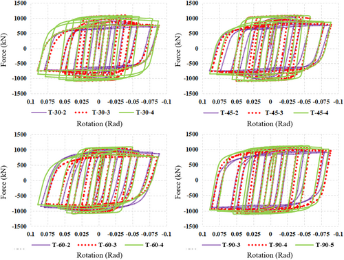
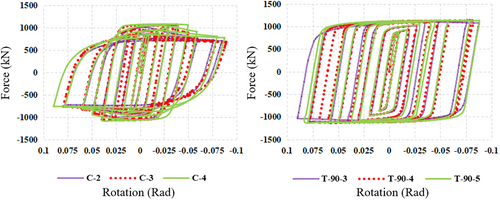
The finite element models were all subjected to cyclic hysteretic loadings as displayed in Figure 4 under the same boundary conditions as illustrated in Figure 9. The hysteretic responses of the case study finite element models are presented in Figure 14. By comparing the link beams with trapezoidal webs, the link beams with 30-degree angle it is evident the increase in the number of web waves will result in higher energy dissipated per cycle (EDC) which is equivalent to the inner chart's area. Furthermore, the T-30-4 finite element model exhibits a much more stable response which is the result of a lower length-to-height ratio compared to the T-30-2 and the T-30-3 models. The same model exhibits less decrease in strength capacity as well. By comparing the results of the T-60 finite element models, it can be noted that while the model with four web waves exhibits higher strength capacity, it shows a greater decrease in value compared to the T-60-2 and T-60-3 models after reaching the peak capacity, which is due to the web buckling. The T-90 models all exhibited wider loops indicating the best EDC performance. This phenomenon is caused by enhanced buckling prevention due to 90-degree angle and the increased number of the waves. The T-90-8 is the only finite element model that did not exhibit strength degradation. The link beams sinusoidal web exhibited narrower loops compared to the link beams with trapezoidal web with the same number of corrugation webs (see Figure 14).
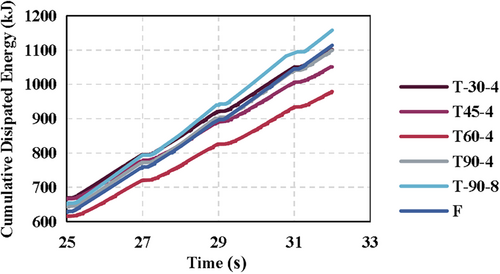
Cumulative dissipated energy (CDE) at different web corrugation angles is presented in Figure 15. The chart clearly shows that the T-60 exhibits the least CDE which is the result of web buckling. While the corrugation successfully delayed the web buckling, however, the number of waves proved significant importance in the CDE. The T-90-8 outperformed all finite element case studies, showing the highest CDE at the end of the cyclic simulation with a 17.7 increase compared to T-30-4.
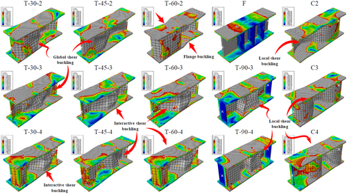
By comparing the T-90 finite element models containing more web corrugation waves, it is evident that the buckling mode in all the models with 90-degree corrugation angle is the local shear buckling (see Figures 16 and 17). Additionally, increasing the corrugation waves results in a drastic decrease in the buckling deformation, to the point that it is prevented in the T-90-7 and T-90-8 models, just like the benchmark model (F). Most interestingly, the benchmark model (F) and T-90-7 performed similarly in the flange stress distribution as well, showing partial yield close to the link beam ends, however, the T-90-8 model surpassed even the benchmark model by preventing yield almost completely in the flanges. It is also necessary to mention that all finite element models are lighter in terms of the steel volume used. This suggests the optimum performance is achieved by the T-90-8 model.

In Figure 18, the plastic plain strain distribution of the finite element (FE) models is presented. Notably, the sinusoidal models exhibit a localized buckling phenomenon, whereas the T-30-4 model demonstrates a more evenly distributed plastic strain pattern. This observation is in line with our earlier comparisons, reinforcing the notion that an increase in the number of web corrugation waves leads to a reduction in web buckling susceptibility. Specifically, the F model displays a 10% higher plastic strain magnitude when contrasted with the T-90-8 model (see Figure 19), indicating a superior performance for the former configuration. Furthermore, the T-90-8 model is lighter compared with the F model by 4.5% in weight, highlighting its low cost and efficiency. An essential aspect of the proposed link beam design is its ability to synergistically integrate multiple advantages. By optimizing material usage and enhancing cyclic response, the proposed link beam demonstrates a higher level of efficiency. This advantageous combination of attributes lends considerable merit to the proposed design's suitability for practical applications. Moreover, the T-90-7 and T-90-8 show no fracture, which is quite welcoming due to the fact that they are as effective in withstanding the induced forces as the benchmark model (F), yet they are lighter, ergo more efficient.
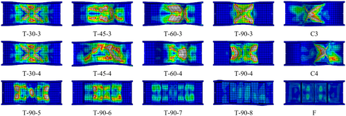

The robustness of the proposed link beam design is validated by these comprehensive findings, which provide substantial evidence of its superior performance in terms of reducing web buckling, mitigating plastic strain, and overall structural efficiency. These outcomes reinforce the viability and potential impact of adopting the proposed link beam configuration in practical engineering and construction projects. The accumulated knowledge from this investigation contributes significantly to the advancement of structural design practices and offers a valuable framework for developing resilient and efficient link beam systems.
4.3 Buckling Modes
As previously stated in the literature review, local shear buckling is related to a solitary flat panel, whereas global shear buckling encompasses multiple panels with buckles extending diagonally across the entire web's height. Interactive shear buckling, conversely, arises from the interplay between local and global shear buckling and entails a small number of panels [13]. The most desirable mode is the local buckling shape, and then the interactive, consequently, the global buckling mode is an indicator of insufficient constraints in the web. Based on previous discussions, the buckling modes of the studied models are categorized in Table 3.
| Corrugation no. | Corrugation angle | ||||
|---|---|---|---|---|---|
| 30° | 45° | 60° | 90° | C | |
| 2 | G | G | Flange Buckling | N.A. | N.A. |
| 3 | I | G | I | L | I |
| 4 | I | G | I | I | I |
| others | I | I | L | No buckling | No buckling |
- Abbreviations: I, interactive buckling; G, global buckling; L, local buckling; N.A., not accounted.
4.4 Cyclic Response Parameters
Whilst evaluating the seismic performance of structural fuse elements, there are three essential factors to consider: ductility, stiffness, and energy dissipation capacity. Ductility refers to the ability to deform without a sudden or significant decrease in the resistance strength of these elements. Stiffness is a critical parameter for assessing their ability to withstand deformations and conduct a comprehensive elastic analysis of the components. The energy dissipation capacity of these elements indicates their capacity to absorb earthquake energy generated by subsurface vibrations. This capacity is typically achieved by either accepting inelastic damage to structural members or employing damping devices. The overview of the cyclic response parameters is depicted in Figure 20.
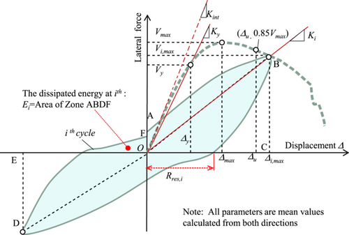
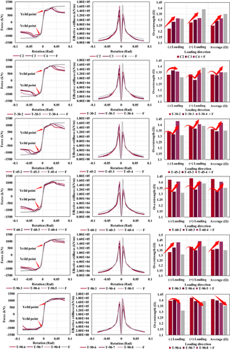
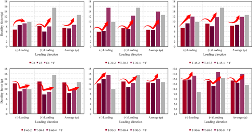
Figure 21 illustrates the derived backbone curve along with effective stiffness and overstrength factors for the case study models. The results show that the finite element models with 3 web corrugation waves exhibit the least overstrength factor in almost all cases in the trapezoidal models. The sinusoidal models show a linear trend showing an increase in overstrength in higher quantities of the web corrugation waves. It is worth noting that the T-90 cases show a decreasing trend in overstrength factor in finite element models with 6, 7, and 8 corrugation waves accordingly, however, all the mentioned cases still exhibited higher values of overstrength compared with the benchmark model (F). All cases exhibited lower values of effective stiffness after yield point in contrast to the benchmark model (F), although less steel material was also used in all finite element models as well. The T-90 models showed an average overstrength value of 1.39 in the range of 1.36–1.41, while the benchmark model overstrength was equal to 1.35. All finite element models showed an almost identical initial effective stiffens up to the yield point in comparison with the benchmark model (F), indicating that as long as the corrugated web thickness is the same as the conventional link beam the stiffness can be calculated in the same manner. The ductility factor (μ) for each finite element model is calculated and presented in the Figure 22. As evident, The T-90 models are eighter as almost ductile or more ductile than the benchmark model (F), exhibiting ductility factors ranging from 12.34 to 17.85, compared to 12.62 of the (F) model. As previously discussed, the T-90 models also exhibit higher values of overstrength, proving that the cyclic response of the stated models is drastically improved compared to the (F) model. In Figure 16 the von Mises stress distribution in the developed and analyzed finite element models is illustrated. The results show that the T-60-2 exhibited unwelcomed buckling mode involving the link beam flange buckling. This phenomenon is consistent with previous findings that showed the mentioned finite element model exhibited degraded response. The T-30-2, T-45-2, and T-30-3 models showed global shear buckling mode as described in the literature review [22]. It is worth mentioning that the benchmark model (F) is initially designed in a way to prevent any buckling, hence, the dominant response is shear yield in the web and partial flange yield. As evident the increase in the angle and number of waves in the corrugation causes the buckling shape to become interactive shear buckling in T-45 and T60 with 3 or 4 waves. Moreover, the T-90 finite element models and all C models exhibited local shear buckling. The ductility factor (μ) is calculated as the displacement/rotation corresponding to force equal to 80% of the maximum force response divided by the yield point displacement/rotation (0.08 displacement was considered as the ultimate rotation capacity per AISC-360 [10]).
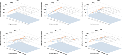
In this section, the calculated EVDs for case study models are compared in a way to assess the influence of corrugation waves, corrugation, angle, and sinusoidal and trapezoidal corrugation shape. The maximum calculated EVD was equal to 14.4% for the F model at the largest cycle and this minimum value was 1.82% for the T-60-2 model at the initial cycle. The average EVD values were equal to 10.2%, 8.96%, 8.2%, 8.8, and 8.59% for the T-30, T-45, T-60, T-90, C shape models. Furthermore, as depicted in Figure 23, the increase in wave number increases the exhibited EVD in all specimens. Also, the C shape specimens performed almost similarly to the T-60 models, yet with slightly higher damping values. Overall, higher corrugation angles decrease the exhibited EVD in small cycles, yet increases the EVD in the large cycles at 0.15 Rad.
5 Conclusions
In conclusion, this comprehensive study delved into the vital role of link beams in eccentric braced frames, serving as the primary structural element to withstand earthquake-induced lateral drifts through substantial deformation. The investigation was centered on enhancing rotation capacity, energy dissipation, and overall performance by integrating corrugated web plates. By carefully selecting 18 case studies, we ensured the thorough consideration of influential parameters, such as the corrugation shape (trapezoidal or curved web plate), angles of the corrugated web plate, and the number of angles/curvatures of the web plate. Through the development of Finite Element micro models, these configurations were subjected to both monotonic and cyclic shear loading, enabling in-depth analysis and evaluation. The most noteworthy outcomes of this investigation are as follows:
The monotonic responses of the finite element models unequivocally demonstrate that web corrugation can effectively delay web buckling in link beams. However, the extent of this achievement is contingent upon the quantity of web waves present. The same observation also holds true for any increase in the wave angles.
The increase in the wave and beam longitudinal axis angle has a substantial impact on the energy dissipation observed in the cyclic responses of the finite element models. Notably, the T-90 models, especially the T-90-8 configuration, exhibited remarkably higher cumulative energy dissipation, with an approximate increase of 17.7%.
The sinusoidal web corrugated link beams exhibited concentrated plastic strain, leading to earlier web buckling compared to the other case study finite element models, indicating inferior performance. Additionally, this type of corrugation is complex to produce, potentially leading to increased construction costs. Overall, the sinusoidal web corrugation, despite lacking sharp edges, failed to distribute stress as effectively as the other case study models.
The T-90 models demonstrate either similar or higher ductility compared to the benchmark model (F), with ductility factors ranging from 12.34 to 17.85, in contrast to the (F) model's ductility factor of 12.62. Additionally, as discussed earlier, the T-90 models exhibit significantly improved cyclic response, as indicated by higher overstrength Factor (Ω0) values ranging from 1.36 to 1.41 compared to the (F) model. This improvement in the cyclic response confirms the enhanced performance of the T-90 models over the benchmark model (F).
It is evident that the buckling shape shifts to interactive shear buckling in T-45 and T60 when the angle and number of waves in the corrugation increase, especially in cases where 3 or 4 waves are present. Additionally, both the T-90 finite element (FE) models and all C models displayed occurrences of local shear buckling.
The maximum EVD for the F model was calculated equal to 14.4% at the largest cycle while the minimum value was derived as equal to 1.82%, for the T-60-2 model at the initial cycle. The average EVD values were equal to 10.2%, 8.96%, 8.2%, 8.8, and 8.59% for the T-30, T-45, T-60, T-90, C shape models at 0.15 Rad.
The T-90-8 link beam configuration demonstrated superior performance compared to all other case study finite element models, including the conventional link beam with a flat web and stiffeners (model F). The T-90-8 model exhibited higher energy dissipation capabilities, higher strength, and ultimate rotation capacities, while also being 4.5% lighter. These results validate the higher levels of efficiency and robustness achieved by the T-90-8 link beam design.
While this study extensively assessed crucial aspects of the link beam corrugation configuration, it also identified certain uncertainties that warrant further attention and rigorous scrutiny. Despite the meticulous investigations conducted, there remain areas of ambiguity and intricacies that demand deeper exploration and analysis. To ensure the comprehensive understanding and reliability of the findings, these unresolved uncertainties necessitate dedicated research efforts and thorough scrutiny in future investigations. Addressing these gaps in knowledge will not only refine our comprehension of link beam behavior but also enhance the validity and applicability of the study's conclusions. Thus, continued research and scrutiny are imperative to unravel the complexities surrounding link beam corrugation and to pave the way for more informed and effective structural design practices.
Acknowledgments
The authors have nothing to report.
Conflicts of Interest
The authors declare no conflicts of interest.


