Life-cycle seismic fragility of a cable-stayed bridge considering chloride-induced corrosion
Abstract
The coastal or sea-crossing bridges located in seismic regions are experiencing long-term chloride-induced corrosion in their life cycles and have a high risk of suffering from strong earthquakes. Thus, the fragilities of these bridges must be properly evaluated under the multiple hazards of corrosion and earthquake. Conventional fragility assessment requires expensive computational efforts despite extensive applications in previous research. To this end, this paper proposes a life-cycle fragility analysis framework based on the endurance time method to investigate the deterioration impact on the seismic fragility of bridges. An example sea-crossing cable-stayed bridge is utilized as a case study and modeled by OpenSees considering different service years. The life-cycle fragility curves of the example bridge are generated using the artificial endurance time series. Fragility analysis results show that the proposed method is capable of assessing the life-cycle seismic fragility of the bridge with high efficiency. The bearing shows a higher damage probability than the pylon and pier. As the service time increases, the structural deterioration has a marginal impact on the system fragility of the bridge, while the component fragility varies across different components. The structural deterioration results in beneficial effects on the pylon and the bearing at the pylon but exerts adverse effects on the pier and the bearing at the pier.
1 INTRODUCTION
With the increasing construction of transportation infrastructures, a large number of long-span sea-crossing bridges, such as the China East Sea Bridge, the Hangzhou Bay Bridge, the Pingtan Strait Rail-cum-road Bridge, and so forth, have been built in China. Bridges exposed to marine environments are vulnerable to chloride erosion in their service lives, thus leading to structural deterioration and reducing the sustainability of bridges.1 Generally, chloride diffuses into the concrete and leads to the corrosion of steel rebar, further reducing the load-bearing capacity of the structure.2 On the contrary, the sea-crossing bridges located in seismic regions may suffer from earthquakes in their life cycles. Consequently, the pristine seismic design for the bridges may not meet the expected requirements when the bridges deteriorate in a corrosive environment. In addition, the life-cycle contexts of bridges are not considered in current seismic design codes3; thus, the seismic performance of bridges may be overestimated during their lifetime. With the rapid development of bridge construction, the design service life of long-span cable-stayed bridges is prolonged and the life-cycle seismic damage of bridges has received widespread attention. Therefore, the seismic performance of sea-crossing cable-stayed bridges in their lifetime should be properly evaluated to ensure their durability and serviceability.
In the last two decades, a large number of bridge structures exposed to marine environments were observed to experience severe chloride-induced corrosion and performance degradation.1 As such, extensive research has been performed to investigate the seismic performance and damage of deteriorating bridges.4-9 For example, Choe et al.4 developed a new probabilistic model for the seismic demand of deteriorated reinforced concrete (RC) bridges by considering various uncertainties, and the model was applied to estimate the lifetime seismic fragility of a single-bent bridge. Ghosh et al.5 investigated the impact of service life on the seismic fragility of multispan continuous highway bridges exposed to deicing salt environments, and they concluded that the seismic vulnerability of bridges significantly increases throughout their life cycle. In the recent literature, Cui et al.10 proposed an improved steel bar corrosion model that considers pitting corrosion and a change of the after-cracking corrosion rate, and then the proposed model was used to assess the time-dependent seismic fragility of RC bridges. In addition, based on the fragility analysis method, Vishwanath and Banerjee,11 Mortagi and Ghosh,12 and Pang et al.13 estimated the life-cycle seismic resilience and economic loss of deteriorating bridges. The results demonstrated the importance of seismic fragility assessment in the life-cycle context.
The above-mentioned studies on the time-dependent seismic performance of corroded bridges indicated that the fragility analysis is a common methodology for assessing the safety of bridges under seismic hazards. However, expensive computational efforts are required to obtain the fragility curves of bridges during their lifetime if using conventional methods such as incremental dynamic analysis (IDA) or cloud analysis. To improve the computational efficiency of the structural dynamic analysis, the endurance time method (ETM) is applied to calculate the seismic response of structures by inputting predefined intensifying ground motions.14 Recently, ETM has been extensively used by contemporary researchers as an efficient technique for structural performance assessment under earthquake events. Guo et al.15 investigated the seismic behavior of a three-span highway bridge with the inclusion of pounding effects based on ETM and validated the sufficient accuracy compared to the IDA method. Tavazo et al.16 developed the fragility curves of an RC frame based on ETM and the IDA method, respectively, and found that the ETM-based fragility analysis framework could significantly reduce the computational cost. Additionally, Wei et al.17 evaluated the fragility of sea-crossing cable-stayed bridges under scour and earthquake hazards. The research results indicated that ETM could reduce the computational effort of fragility analysis with high accuracy. These studies demonstrate that ETM has greater potential for use in the fragility analysis of bridges than the IDA method; thus, the application of ETM for the vulnerability estimation of bridges under multiple-hazard scenarios remains to be further investigated.
On the basis of the advantages of ETM in the seismic performance assessment of structures, this paper investigated the life-cycle seismic fragility of a sea-crossing cable-stayed bridge under corrosion environments. The chloride-induced corrosion process of RC was introduced at first. The methodology of endurance time analysis was then presented. Based on ETM, the seismic fragility analysis framework of bridges throughout the life cycle was proposed. The time-dependent numerical model of a sea-crossing cable-stayed bridge subjected to chloride corrosion was established. Soil–structure interactions (SSIs) and hydrodynamic effects for piles and pile caps were considered. Then, the time-dependent seismic fragility curves of the bridge were developed according to the ETM-based analysis framework. The impacts of the service time on the seismic fragility of the bridge component and system were comprehensively discussed.
2 ETM-BASED LIFE-CYCLE FRAGILITY ANALYSIS FRAMEWORK CONSIDERING CHLORIDE-INDUCED CORROSION
2.1 Performance degradation of RC members due to chloride-induced corrosion
Although some studies indicated that icorr was time-varying and related to the corrosion pattern and zone,8, 10, 21 for simplicity, only the uniform corrosion of steel in the atmospheric zone is taken into account in this paper and the corrosion current density icorr is assumed to be a constant. The deterioration parameters considered in the chloride-induced corrosion process are listed in Table 1.
| Parameter | Dc (mm2/a) | Cs (kg/m3) | Cr (kg/m3) | icorr (μA/cm2) |
|---|---|---|---|---|
| Value | 63.072 | 2.95 | 0.8 | 3 |
2.2 Generation of the endurance time acceleration function (ETAF)
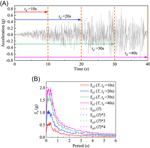
Based on Equations (7) and (8), four ETAFs are generated using the ETAG (Endurance Time Accelerogram Generator) programmed in MATLAB; herein, only the acceleration time series and response spectra of ETAF-1# are shown in Figure 1 for brevity. Figure 1 shows that the amplitude of ETAF-1# increases with the time duration, and the response spectra during different duration times are in good agreement with the corresponding target spectra.
2.3 Component- and system-level fragility analysis based on ETM
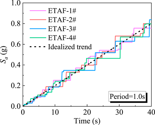
It is noteworthy that the calculation of seismic fragility also depends on IMs. Previous fragility research indicated that both the peak ground acceleration (PGA) and spectral acceleration (Sa) were used as IMs. However, the ETAF is synthesized based on the target response spectrum and the dispersion of the regression model is minor when Sa is used as IM. Also, Hariri-Ardebili et al.24 suggested that Sa was more appropriate than PGA to be used as IM when estimating the seismic fragility of structures through ETM. Therefore, the spectral acceleration of ETAF with a structural period equaling 1.0 s is used as IM in this study. For the conventional fragility analysis (e.g., IDA method), the ground motion is usually scaled up and down to generate n seismic inputs with different intensities and obtain the structural demand through dynamic analyses. Thus, n time–history analyses are required to calculate the parameters of a probabilistic demand model. A larger value of n results in a more accurate probabilistic demand model. However, compared to the conventional method, the ETM-based method only requires one time–history analysis to obtain the demand model since the ETAF has continuously amplified intensities and thus the computational efficiency is improved by n times. Figure 2 shows the change in spectral acceleration (IM) of four generated ETAFs over time and shows good consistency with the idealized trend. By inputting the four ETAFs, the enveloped demand (EDP) of structures over time could be obtained. By combining IM and EDP, the probabilistic demand model can be acquired by the linear regression in Equation (10). According to the suggestions of HAZUS99,25 the value of in Equation (9) can be taken as 0.4 when using Sa as IM. Furthermore, the structural capacity is affected by chloride intrusion; thus, the seismic capacity (μc) of structures is considered to change with service time in this study. By combining Equation (9) and (10), the seismic fragility of different bridge components based on ETM can be calculated.
3 NUMERICAL MODELING OF THE EXAMPLE BRIDGE DURING A LIFETIME
3.1 Description of the example cable-stayed bridge
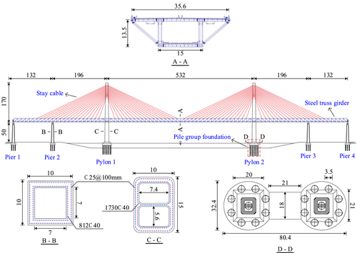
A double-pylon sea-crossing cable-stayed bridge is selected as the example bridge. The elevation view and cross-sections of the bridge are shown in Figure 4. The bridge has a length of 132 + 196 + 532 + 196 + 132 = 1188 m and consists of two RC pylons, four RC piers, a steel truss girder with a uniform cross-section, and double-plane cables with a semifan arrangement. The heights of the pylon and the pier are 220 and 50 m, respectively. The girder has a width of 35.6 m and a height of 13.5 m, respectively. The substructure of pylons is composed of a dumbbell-shaped pile cap with the dimension of 80.4 m × 32.4 m × 10 m and 18 piles with a diameter of 4.5 m and a length of 47 m. The upper 21 m of the pile group foundation is submerged in seawater and the residual part is embedded in the soil, whose effective weight is 30 kN/m3. The compressive strength of concrete for the pylon is 55 MPa, and the compressive strength of concrete for the pier and pile is 45 MPa. The cross-section and steel reinforcement arrangement for the pylon and pier are shown in Figure 4. The yield strengths of longitudinal reinforcements and stirrups are 400 and 335 MPa, respectively. The stay cables with a tensile strength of 1680 MPa are installed between the pylon and the bridge deck. The fixed bearing is installed between Pylon 1 and the girder, and the movable bearing in the longitudinal direction is installed on the piers and Pylon 2.
3.2 Finite element modeling
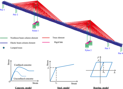
The finite element model of the example bridge is built using OpenSees software, as shown in Figure 5. The steel truss girder is modeled using elastic beam–column elements as it is expected to remain elastic during earthquakes. Nonlinear beam–column elements are used to capture the inelastic behavior of the pylon, pier, and pile foundations. The concrete model is established using Concrete01 material in OpenSees and the stress–strain relationship of steel bars is modeled using Steel02 material. The zero-length element is used to model the movable bearing in the longitudinal direction. The constitutive laws of concrete, steel bar, and bearing are shown in Figure 5. The initial strain material (InitStrainMaterial) and truss element are used to simulate the steel cables with the initial strain. For the pile group foundation of pylons located in seawater and soil, the SSI effect is simulated using p–y spring models according to the formulae suggested by API,27 and the added mass is calculated using the Morison equation and potential flow theory to consider the hydrodynamic effect.28 The pile cap is generally assumed to be a rigid body under seismic excitations; thus, it is modeled by the lumped mass and connects the piles with rigid links. Because the piers are located on the rocky site, the piles for the piers are neglected and fixed constraints are used to the base of the piers in this study.
3.3 Time-dependent characteristic of structural deterioration
Once the corrosion initiation time ti is determined, the time-dependent characteristics of steel bars can be obtained by combining Equations (4)–(6). It should be noted that only the corrosion of the pylon and pier is considered in this paper. The corrosion effects on the bearing and cables are not considered as they are maintained annually and replaced almost every 10 years. The truss beams and cables are not discussed in this paper since they usually remain elastic and undamaged during earthquakes.29 Figure 6 shows the time-dependent properties of longitudinal steel rebars and stirrups for the pylon and pier. As shown in Figure 6, the diameter and yield strength of steel rebars remain constant in the first few years as corrosion is not initiated. With the accumulation of chloride ions, the steel surface starts to rust and the net cross-sectional area of the steel rebar decreases over service time, thus resulting in an increase in the corrosion ratio and reduction in the yield strength. Additionally, the steel rebar for the pier shows a faster corrosion rate than that for the pylon because the pier has a smaller cover depth. Similarly, the stirrup corrodes faster than the longitudinal rebar whether for the pylon or for the pier.

With increasing service time, corrosion of stirrups can lead to a reduction in concrete confinement and degradation in structural capacity. Therefore, the deterioration of confined concrete is considered based on Mander's model30 in this paper. Note that, for the unconfined concrete, the deterioration effect is neglected since it has marginal impacts on the seismic performance of bridges.
Different bridge components may suffer various extents of damage under seismic loadings. Hence, the structural capacity, namely, μc in Equation (9) can take on various damage limit values to calculate the seismic fragility of components under different damage states. In this paper, the values of μc for pylons, piers, and bearings are determined on the basis of the damage indexes suggested by Choi et al.26 The damage indexes for different components are divided into four damage states, that is, slight, moderate, extensive, and complete. Table 2 summarizes the four damage states and the values of damage indexes for the pylon, pier, and bearing.
| Component | Damage index | Unit | Damage state | |||
|---|---|---|---|---|---|---|
| Slight | Moderate | Extensive | Complete | |||
| Pylon and Pier | Curvature ductility (μϕ) | - | 1 < μϕ < 2 | 2 < μϕ < 4 | 4 < μϕ < 7 | μϕ > 7 |
| Bearing | Displacement (Δ) | mm | 50 < Δ < 100 | 100 < Δ < 150 | 150 < Δ < 255 | Δ > 255 |
4 LIFETIME SEISMIC FRAGILITY ASSESSMENT OF THE EXAMPLE BRIDGE
4.1 Component fragility curves of the bridge in a lifetime
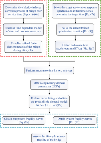
The ETM-based fragility analysis framework proposed in Section 2 is used to develop the fragility curves of bridge components at different service years. In this study, the pristine state and five service years equaling 20, 40, 60, 80, and 100 years are considered to investigate the time-dependent seismic fragility of the bridge in a lifetime. Only the fragility of the example bridge along the longitudinal direction is discussed because the bridge is more vulnerable to earthquakes in the longitudinal direction than in the transverse direction.
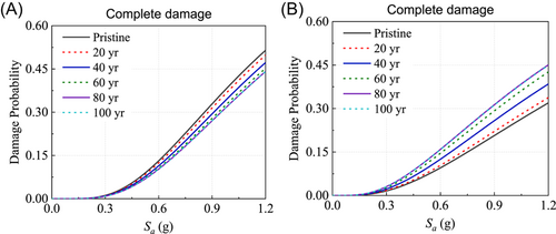
Figure 7 shows the life-cycle fragility of the bearings for the pylon and the pier under complete damage states. For brevity, the fragility curves under other damage states are not shown herein. As shown in Figure 7, for the same service time, the bearing at the pylon is more vulnerable than that at the pier under strong ground motions. For example, at the pristine state (i.e., service time = 0 year) and Sa = 1.0 g, the damage probability of the bearing at the pylon is 39.4%, which is higher than that of the bearing at the pier (24.5%). On the contrary, with increasing service years, the damage probability of the bearing at the pylon decreases, while the damage probability of the bearing at the pier increases. Taking Sa = 0.8 g as an example, the damage probability of the bearing at 100 years for the pylon and the pier changed by around −19% (drop) and 55.2% (rise), respectively, compared to the pristine state. Note that the change is amplified with increasing Sa. It can be seen that the structural deterioration has beneficial and adverse effects on the bearing fragility for the pylon and the pier, respectively. This phenomenon may result from the difference in the corrosion level between the pylon and the pier.
The time-dependent fragility curves for the pylon and the pier under different damage states are shown in Figures 8 and 9, respectively. It can be observed that the pier is more fragile than the pylon under earthquakes because of the higher damage probability. At the pristine state, the maximum probability of slight damage for the pylon is about 56.2%, while that for the pier is about 92%. Figure 8 shows that the pylon tends to show slight or moderate damage in the range of earthquake intensities considered in this study. This is because it has quite low damage probabilities under the extensive and complete damage states. Similarly, Figure 9 shows that the pier hardly suffers complete damage due to the low damage probability (below 0.05%). Moreover, the fragility curves of the pylon in Figure 8 demonstrate that the damage probability decreases marginally before 40 year over the service time, but remains almost unchanged after that. On the contrary, as shown in Figure 9, the fragility of the pier increases over service time. For example, at Sa = 0.6 g, the probability of the pier developing slight and moderate damage increases by around 11.7% and 57.7% in a lifetime (from the pristine state to 100 years), respectively.
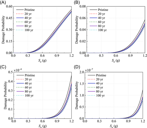
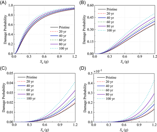
Overall, the impacts of chloride-induced corrosion on the component fragility of the bridge vary with components. For the pylon and the bearing at the pylon, structural deterioration or an increase of service time can reduce the seismic vulnerability with a small amplitude. However, for the pier and the bearing at the pier, the fragility increases under the life-cycle deterioration effect. The main reason is that the concrete cover of the pier is thinner than the concrete cover of the pylon. Consequently, the pier is more vulnerable to corrosion effects than the pylon during a lifetime. The pier shows a higher corrosion level than the pylon at the same service time. Due to the discrepancy in the corrosion level between the pier and the pylon, the structural dynamic properties are changed and the vibration mode shape participation of the overall bridge is redistributed. Under the seismic excitations, more seismic energy is transferred from the pylon to the pier.
4.2 System fragility curves of the bridge in lifetime
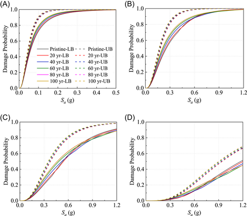
The system fragility curves of the example bridge during a lifetime are plotted in Figure 10. As shown, the damage probability of the bridge system is higher than the damage probability of any component. The actual system fragility of the bridge is between the lower bound (LB) and the upper bound (UB). It can be seen that the upper bounds of system damage probability at different service times are almost identical or show a very slight increase, whereas the lower bounds show some differences depending on the damage states and Sa. For the slight damage state of the bridge system, it is clear that the upper bound increases with the service time in a small range of earthquake intensity. However, the lower bounds under moderate, extensive, and complete damage states vary with the change of Sa. With Sa below 0.4 g, the lower bound shows a similar change to the upper bound, which shows a slight increase over the service time. As Sa increases, the lower bound tends to decrease with the service time. This change is due to the fact that the lower bound is related to the maximum damage probability of components according to Equation (11). Under minor earthquakes, the bearing fragility for the pier dominates the system fragility due to the higher damage probability. Thus, the system fragility increases with the service time, which is consistent with the time-dependent law of the bearing fragility for the pier. With increasing earthquake intensity, the bearing fragility for the pylon may exceed that for the pier and affect the system fragility of the bridge. Therefore, the time-dependent law of system fragility is compatible with the bearing fragility at the pylon. In general, structural deterioration has little effect on the system fragility of the example bridge, while the influence of deterioration on the component fragility cannot be neglected during the life cycle.
5 CONCLUSIONS
This paper presents an efficient fragility analysis framework based on ETM to assess the life-cycle fragility of bridges under chloride-induced corrosion. An example sea-crossing cable-stayed bridge is modeled using OpenSees with the consideration of structural deterioration over time, SSI, and hydrodynamic added mass. The endurance time–history analyses are performed to calculate the component and system fragility of the example bridge. The life-cycle fragility curves of the bridge are developed and the impacts of service time on the component and system fragility of the bridge are discussed. The main conclusions can be drawn as follows:
The proposed ETM-based fragility analysis approach can be used to efficiently compute the fragility of the bridge through only several dynamic analyses. The comparison of fragility for different bridge components indicates that the bearing is more vulnerable than the pylon and the pier under earthquakes due to its higher damage probability. Within the range of considered earthquake intensities in this study, the damages of the pylon and pier area in the almost below moderate and extensive damage states, respectively.
The influence of structural deterioration on the component-level fragility of the bridge varies with the components. As the service time increases, the deterioration effect increases the fragility of the pier while decreasing the fragility of the pylon, which is identical to the time-dependent fragility law of the bearing at the pier and the pylon, respectively. Due to the larger corrosion level, the pier is more vulnerable than the pylon under earthquakes and the structural deterioration tends to transfer the damage from the pylon to the pier.
With increasing service years, chloride-induced corrosion has little impact on the system-level fragility of the bridge. However, the structural deterioration may exert negative effects on the bearing at the pier and the pier. The component fragility of the example bridge during a lifetime may be underestimated without consideration of the deterioration effects.
In summary, the ETM-based fragility analysis framework proposed in this paper is capable of rationally assessing the life-cycle seismic fragility of sea-crossing cable-stayed bridges. In the meantime, the computational efficiency of the fragility analysis is improved as well. The proposed methodology provides an efficient tool for the seismic fragility analysis of bridges during life cycles. In addition, this method can be extended to the seismic performance assessments of other engineering structures exposed to corrosion environments.
ACKNOWLEDGMENTS
The authors would like to acknowledge the financial support of the National Natural Science Foundation of China (Grant No. 51978578) and the Scientific Research Fund (No. ASFL-21-001) of the Key Laboratory of Seismic Engineering Technology in Sichuan.
CONFLICTS OF INTEREST
The authors declare no conflicts of interest.


