Seismic control of a smart structure with semiactive tuned mass damper and adaptive stiffness property
Abstract
To reduce structural responses under earthquake excitations effectively and improve their resilience, a smart structure with a semiactive tuned mass damper (STMD) on the top story and a semiactive adjustable stiffness device (SASD) on the first story which contributes to the structural adaptive stiffness property is developed in this study. The SASD consists of a diamond spring device composed of four linear springs and an electromagnetic actuator, which can change the angle of the diamond device and therefore retune the stiffness. Two typical STMDs developed previously are reviewed first, which are diamond device-based STMD with variable stiffness and damping and pendulum-type STMD with variable frequency and eddy current damping, respectively. Numerical results show that the proposed STMD has a better control performance than passive-tuned mass damper and STMD with variable stiffness or damping acting independently. To enhance the seismic protection of the structure with an STMD on the top story further, based on the principle of base isolation, a diamond device-based SASD is applied to the first story. The linear quadratic Gaussian-based variable stiffness algorithm for SASD is proposed. A 10-story building is presented as a case study. The variable stiffness range of SASD is discussed in detail, while it is found that a ±50% variable stiffness range achieves the best earthquake mitigation. Control effects of different numbers of SASD implemented along the height of the building are compared as well. Numerical results show that with the increase in the number of SASDs, the earthquake mitigation effect is better; however, the magnitude of the increase is decreasing. The smart structure with the combined SASD and STMD has an excellent seismic protection performance and is better than with SASD or STMD acting independently. Meanwhile, it is found that the proposed combination has a similar control effect to four SASDs installed from the first story to the fourth story, respectively, while it can reduce the number of additional electromechanical systems and the influence on the use function of the building.
1 INTRODUCTION
An earthquake is a very destructive and dangerous natural disaster, which will cause a serious impact on people's life and property safety.1, 2 How to effectively protect the safety of building structures under earthquake, improve its resilience3-6 and control the dynamic response has always been a hot research topic in the field of earthquake engineering and structural control.7-9
The tuned mass damper (TMD), which is composed of mass, spring, and damping elements, is a popular mechanical device for vibration control.10-14 For a passive TMD with a constant mass, the control effect is dependent on the frequency ratio and damping ratio.15 When these two ratios are well-tuned, a passive TMD can have satisfactory performance.16 Dai et al.17 proposed a viscoelastic TMD with a large mass ratio. Xiang et al.18 optimized a variable friction pendulum TMD. Wang et al.19, 20 proposed a pendulum-pounding TMD for structural seismic protection. Jiang et al.21 controlled the vibration of a submerged cylindrical pipe using a pounding TMD. Wang et al.22 presented a two-phased nonlinear TMD for base-isolated structures. He et al.23 investigated the effective damping ratio of TMD based on acceleration. Fallahpasand et al.24 proposed a pendulum TMD with nonlinear viscous damping, while Wang et al.25 presented TMDs enhanced by clutching inerters. From the above-reviewed references, it can be found that a well-optimized passive TMD has a good control effect; however, it is sensitive to the frequency ratio and a mistuned TMD can even have a negative effect.26, 27 Further, considering the real earthquake with a wide frequency range, a passive TMD cannot ensure its earthquake mitigation performance.26
To improve the seismic protection effect of a passive TMD, an active TMD with an actuator and direct power input to the primary structure is developed.28 Though it has a better control effect, an active TMD will cost lots of power assumption and has a stability problem.29, 30 Compared to the active TMD, a semiactive TMD (STMD) with variable parameters needs less power assumption and has the advantage of inherent stability.31 Susheelkumar et al.32 proposed an adaptive TMD based on the fuzzy sliding mode. Wang et al.33 presented an STMD with variable stiffness for a constructing bridge tower. Kwon et al.34 proposed a standalone TMD with a self-sensing magnetorheological elastomer. It can be known from these studies that the STMD can improve the earthquake mitigation performance of a passive TMD significantly.
Around structural control, Nagarajaiah proposed a semiactive adjustable stiffness device (SASD),35 which consisted of a diamond spring device composed of four linear springs and an electromagnetic actuator. The actuator could change the angle of the diamond spring device, and therefore retune the stiffness. The diamond device-based STMD for wind-induced vibration control could be referred to Nagarajaiah and Varadarajan,36 while earthquake mitigation could be seen in Nagarajaiah et al.37, 38 In addition to additional mass dampers, base isolation is another attractive energy dissipation scheme. The short-term Fourier transform-based variable stiffness control algorithm for base-isolated structures with the SASD was proposed by Narasimhan and Nagarajaiah,39 and experimental and numerical studies about the smart base isolation with the SASD could be found in Nagarajaiah et al.40, 41 It can be known from these references that STMD applied on the top story and smart base isolation implemented on the isolated layer are both important and promising because they can not only reduce structural dynamic responses under earthquakes effectively but also have little influence on the use function of the building.
Another attractive seismic protection scheme is the smart structure with adaptive stiffness properties. Similar to the principle of base isolation, it can vary the structural stiffness and frequency in real-time to reduce earthquake-induced responses. Sun and Nagarajaiah42 proposed an experimental study on a single-degree-of-freedom (SDOF) system with an SASD. Karami and Akbarabadi43 developed a smart structure with SASDs according to the integrated subspace-based damage detection algorithm. Karami et al.44 proposed a diamond device-based STMD for nonlinear vibration control, while Azizi et al.45 investigated the adaptive stiffness mechanism of the SASD. From the reviewed literature, it can be found that the smart structure with adaptive stiffness property has a smaller dynamic response than a traditional structure under earthquake excitations.
It can be known from the above two paragraphs that the novel smart structure with adaptive stiffness property has not been extensively studied as STMD and smart base isolation, further research about the new control algorithm and parameter discussion are necessary. The control effect of a semiactive controller is mainly dependent on its control algorithm. To further improve the earthquake mitigation performance, a more effective and robust semiactive controller algorithm for SASD is needed, while its key parameters should be discussed and optimized as well. Besides, it is shown in Karami et al.43-45 that for a tall building, several SASDs are needed usually, while the practical application of this novel control strategy may be restricted by the influence of the building function. Therefore, it will be meaningful to propose a comparable and alternative seismic mitigation smart structure, which not only has an excellent control effect, but also has minimal impact on the functional use of the building.
Previous studies by the authors found that the proposed STMD had a better control performance than a passive TMD.46, 47 To enhance the seismic protection of the structure with a STMD on the top story further, based on the principle of base isolation, a diamond device-based SASD can be applied to the first story. The control effect of the combined SASD and STMD earthquake reduction strategy needs to be verified.
To fill this blank, in this paper, two typical STMDs developed previously are reviewed first in Section 2, which are diamond device-based STMD with variable stiffness and damping and pendulum-type STMD with variable frequency and eddy current damping, respectively. Especially, control effects of different TMDs are compared in Section 2.3. Then, the working mechanism of SASD and the linear quadratic Gaussian (LQG)-based variable stiffness algorithm are presented in Section 3. A 10-story building is presented as a case study in Section 3.3. The variable stiffness range of SASD is discussed in detail in Section 4.1, and control effects of different numbers of SASD implemented along the height of building are compared in Section 4.2. The advantage of the smart structure with the combined use of SASD and STMD is highlighted in Section 4.3. Finally, conclusions are drawn in Section 5.
2 STMD
To better understand the working mechanism and control effect of STMD with variable stiffness and damping, two typical STMDs developed previously by the authors are reviewed in this section, which are diamond device-based STMD with variable stiffness and damping in Section 2.1, and pendulum-type STMD with variable frequency and eddy current damping in Section 2.2, respectively. Furthermore, a numerical example is proposed in Section 2.3 to highlight its advanced control effect.
2.1 Diamond device-based STMD
The schematic diagram of diamond device-based STMD is illustrated in Figure 1.
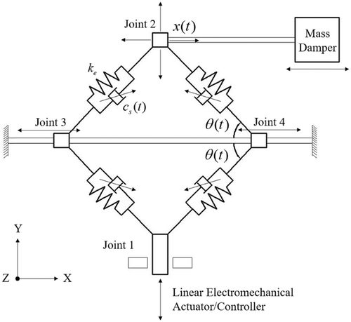
In Figure 1, the diamond device-based STMD consists of a mass whose X-directional displacement is , a diamond spring device which is composed of four linear springs and an electromagnetic actuator, and four semiactive dampers are included as well. The actuator can move in the Y direction and change the angle of the diamond spring device, and therefore retune the stiffness and the X-directional frequency of STMD.
In Figure 1, the frequency of STMD is dependent on and . As a TMD is a frequency-dependent vibration absorber, to achieve a better earthquake mitigation, it should track and catch the structural instantaneous frequency, and then retune itself through varying . In this study, structural displacement signals under earthquake excitations are analyzed and processed using wavelet transformation (WT).48 When the structural instantaneous frequency in each time segment is identified, the diamond device-based STMD can retune its stiffness based on Equation (1) through changing .
2.2 Pendulum-type STMD
The pendulum-type TMD has a wide application in high-rise and supertall buildings. On the basis of this engineering background, the STMD with variable pendulum length (equivalent stiffness and frequency) and eddy current damping is shown in Figure 2.
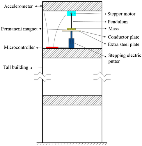
It can be seen in Figure 2 that on the top story, under the guidance of microcontroller, the stepper motor will adjust the pendulum length to retune its frequency.2 The semiactive damping is generated by the adjustable eddy current damper.46 A scaled-model experiment of the adjustable eddy current damper was proposed by Wang et al.,27 it was found that through changing the air gap between the conductor plate and permanent magnets which adsorbed on the mass, the eddy current damping could be adjusted easily by the stepping electric putter.
As for the STMD in Figure 2, the instantaneous frequency is tracked through WT as well, and the damping switching algorithm in Equation (2) is used.
2.3 Numerical simulation
From the previous two sections, it can be known that though electromechanical details of the two STMDs are different, the structural dynamic model and variable frequency and damping control algorithm are the same, and they can both be applied in real projects and are comparable and substitute generally. Usually, the STMD will be implemented at the top story of the building. As for the diamond device-based STMD, it takes up space above the top floor; while for the pendulum-type STMD, it will take up space on several floors below the top floor.
For comparison, a mistuned 1.1 Hz passive TMD is set, and STMDs with variable stiffness only and variable damping only are proposed, respectively, as well. Note that all compared TMDs have the same mass. The mistuned TMD and STMD with variable stiffness only both have the same damping coefficient as the optimized TMD. The STMD with variable damping only has the same stiffness as the optimized TMD. The STMD with variable stiffness can catch the structural instantaneous vibrational frequency using displacement signals through WT and then retune itself, while the STMD with variable damping can switch its damping coefficient between the minimum and the maximum, which are 0 and , respectively, in this study.
Under harmonic base excitations with different frequencies whose amplitudes are all 1 m/s2, maximum structural displacements of the above six cases are compared in Figure 3.
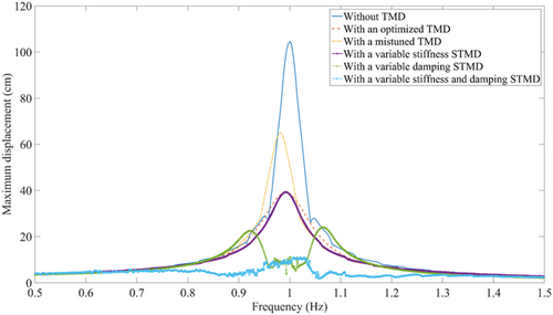
From Figure 3, when the resonance happens, the structural suffers from a huge vibration, while the optimized TMD has a good control effect generally. The mistuned TMD loses its effect especially between the frequency range of 0.9–1.0 Hz. The STMD with variable stiffness has a better performance than the optimized passive TMD when the excitation frequency is deviated from 1.0 Hz, because it can vary its natural frequency and achieves a better response reduction. The STMD with variable damping has an excellent control effect in the resonance frequency range; however, it does not perform well when the excitation frequency is around 0.9 and 1.1 Hz. At last, it is obvious that the STMD with variable stiffness and damping has the best vibration mitigation and achieves the best performance throughout the whole excitation frequency range.
3 EARTHQUAKE PROTECTION SMART STRUCTURE
3.1 Smart structure with SASDs
It has been highlighted and compared in Section 2.3 that the STMD with variable stiffness and damping has the best control effect compared to the passive TMD, and STMD with variable stiffness or damping acting independently. To enhance the seismic protection of the structure with a STMD on the top story, one way is to increase the mass of TMD, while another more interesting and attractive way is the addition of SASD.
The schematic diagram of earthquake protection smart structure with several SASDs which contributes to the adaptive stiffness property is presented in Figure 4.
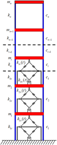
The diamond device-based STMD has been shown in Figure 1 and introduced in Section 2.1. When the mass and semiactive dampers are removed, it becomes a SASD. The joint 2 of SASD in Figure 1 is connected to the upper floor of the building, while the joint 1 will be connected to the lower floor. The added SASD can change the stiffness of its floor and therefore the frequency of the whole building, which contributes to structural adaptive stiffness property.
Based on the principle of base isolation, several SASDs are implemented along the height of the building from the first story. Note that the SASD is evenly arranged along the floor, and only one is arranged on each floor.
In Figure 4, is the number of total SASDs; , , and are the mass, constant stiffness, and damping coefficient of the ith story, respectively; means the variable stiffness of the ith story; represents the total stiffness of the ith story in real time and ; is the total number of floor of the building.
In Equation (7), the variable stiffness range of SASD, and control effects of different numbers of SASD implemented along the height of the building will be discussed and compared in Section 4.
3.2 Smart structure with SASD and STMD
In Section 3.1, to protect a tall building from earthquake excitations, several SASDs are added to achieve the structural adaptive stiffness property. Besides, to reduce the number of additional electromechanical SASDs for economic reasons and the influence on the use function of the building, and to enhance the seismic protection of the smart structure with an STMD on the top story further, based on the principle of base isolation,50, 51 the diamond device-based SASD is only applied to the first story. The schematic diagram of the enhanced earthquake protection smart structure with an SASD on the first story and an STMD on the top story is shown in Figure 5.
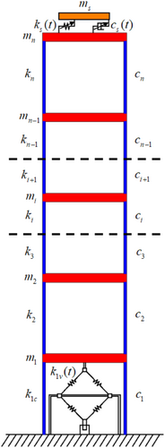
In Figure 5, the SASD can vary its stiffness in real-time according to Equations (5)–(7); the STMD can retune its stiffness based on the displacement signal of the top story according to the WT-based algorithm, and switch its damping coefficient according to Equation (2). The combined control strategy of the smart structure with SASD and STMD is illustrated in Figure 6.
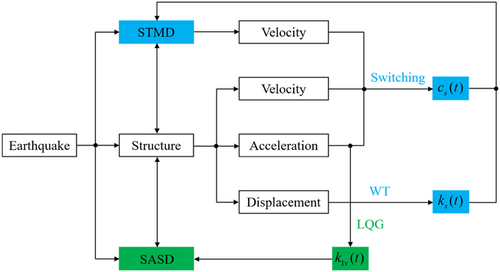
The control effect and performance improvement of the combined use of SASD and STMD will be verified in Section 4.
3.3 Case study
A 10-story building from Lyu et al.52 is used as a case study in this paper. The mass and stiffness of each story are 1.02 × 10⁶ kg and 1.5 × 10⁹ N/m, respectively. The modal damping ratio is assumed to be 2%, which is a simple shear-type model. Through modal analysis, it can be found that the previous three modal frequencies are 0.91 Hz, 2.72 Hz, and 4.46 Hz, respectively, whose modal mass participation coefficients are 84.79%, 9.14%, and 3.09%, respectively.
Eight ground motions with different spectral characteristics are chosen as inputs and are shown in Table 1.
| No. | RSN | Earthquake name | Year | Station name | Component |
|---|---|---|---|---|---|
| 1 | 960 | Northridge-01 | 1994 | Canyon Country—W Lost Cany | NORTHR_LOS000 |
| 2 | 1116 | Kobe_ Japan | 1995 | Shin-Osaka | KOBE_SHI000 |
| 3 | 1158 | Kocaeli_ Turkey | 1999 | Duzce | KOCAELI_DZC180 |
| 4 | 1148 | Kocaeli_ Turkey | 1999 | Arcelik | KOCAELI_ARE000 |
| 5 | 767 | Loma Prieta | 1989 | Gilroy Array #3 | LOMAP_G03000 |
| 6 | 725 | Superstition Hills-02 | 1987 | Poe Road (temp) | SUPER.B_B-POE270 |
| 7 | 826 | Cape Mendocino | 1992 | Eureka—Myrtle and West | CAPEMEND_EUR090 |
| 8 | 125 | Friuli_ Italy-01 | 1976 | Tolmezzo | FRIULI.A_A-TMZ000 |
To highlight the influence of spectral characteristics of ground motion on the dynamic response of the structure, all peak ground motions of the eight earthquakes are normalized to 1 m/s2 in the numerical simulation.
4 PARAMETER DISCUSSION AND NUMERICAL RESULTS
4.1 Discussion of the variable stiffness range of SASD
In Section 3.1, the SASD can vary its stiffness according to the LQG-based algorithm. In this section, the variable stiffness range is discussed and compared. Note that the SASD is only applied on the first story in this section.
In Figures 1 and 4, as for the SASD, when , it achieves the maximum X-directional stiffness, while achieves the minimum stiffness when in an ideal situation. It is mentioned in Section 3.3 that the first story has a stiffness of 1.5 × 10⁹ N/m. It should be noted that when the SASD is implemented, will be weakened to generate a variable stiffness range.
In this section, five typical variable stiffness ranges of the first story are discussed, which are 0.9 –1.1 (SASD ± 10%), 0.7 –1.3 (SASD ± 30%), 0.5 –1.5 (SASD ± 50%), 0.3 –1.7 (SASD ± 70%), and 0.1 –1.9 (SASD ± 90%), respectively. For each case, the minimum stiffness is proposed by the structural constant stiffness, while the variable part is generated by the SASD.
Under the eight ground motions, maximum and root mean square (RMS) displacements of the top story of the smart structure with different variable stiffness ranges of SASD are shown in Table 2, Table 3, and Figure 7, respectively.
| Earthquake | Without control | SASD ± 10% | SASD ± 30% | SASD ± 50% | SASD ± 70% | SASD ± 90% |
|---|---|---|---|---|---|---|
| Northridge-01 | 2.961 | 2.835 | 2.618 | 2.762 | 2.958 | 2.983 |
| Kobe_ Japan | 7.638 | 7.372 | 6.759 | 6.591 | 6.438 | 6.288 |
| Kocaeli_ Turkey-D | 5.499 | 5.381 | 5.096 | 4.985 | 4.797 | 5.240 |
| Kocaeli_ Turkey-A | 2.466 | 2.407 | 2.184 | 1.840 | 2.175 | 2.215 |
| Loma Prieta | 1.606 | 1.591 | 1.568 | 1.548 | 1.552 | 1.564 |
| Superstition Hills-02 | 5.021 | 4.515 | 3.932 | 4.044 | 3.663 | 3.644 |
| Cape Mendocino | 5.584 | 5.191 | 4.537 | 4.355 | 4.323 | 4.524 |
| Friuli_ Italy-01 | 2.637 | 2.565 | 2.411 | 2.207 | 2.491 | 2.445 |
- Abbreviation: SASD, semiactive adjustable stiffness device.
| Earthquake | Without control | SASD ± 10% | SASD ± 30% | SASD ± 50% | SASD ± 70% | SASD ± 90% |
|---|---|---|---|---|---|---|
| Northridge-01 | 1.256 | 1.122 | 0.930 | 1.037 | 1.046 | 1.087 |
| Kobe_ Japan | 2.499 | 2.178 | 1.838 | 2.010 | 2.082 | 2.032 |
| Kocaeli_ Turkey-D | 2.176 | 1.850 | 1.415 | 1.279 | 1.676 | 2.024 |
| Kocaeli_ Turkey-A | 0.726 | 0.641 | 0.520 | 0.458 | 0.536 | 0.581 |
| Loma Prieta | 0.346 | 0.333 | 0.307 | 0.298 | 0.315 | 0.396 |
| Superstition Hills-02 | 1.713 | 1.477 | 1.272 | 1.457 | 1.378 | 1.409 |
| Cape Mendocino | 1.718 | 1.452 | 1.209 | 1.064 | 1.051 | 1.087 |
| Friuli_ Italy-01 | 0.767 | 0.643 | 0.490 | 0.429 | 0.530 | 0.570 |
- Abbreviations: RMS, root mean square; SASD, semiactive adjustable stiffness device.

From the numerical results proposed in Table 2, Table 3, and Figure 7, it can be known that first, when the SASD only has a ±10% variable stiffness range, the maximum displacement reduction is not significant, but it performs better for the RMS response control compared to the structure without SASD; second, when the variable stiffness range enlarges to ±30%, control effects become much better both for maximum and RMS responses; then, as for the SASD with a ±50% variable stiffness range, the earthquake mitigation performance becomes even better generally; at last, when the variable stiffness range becomes larger further, no significant improvement is found, and responses can even be enlarged under some earthquakes.
Therefore, considering the control effect as discussed above, a ±50% variable stiffness range of SASD is suggested and chosen in the following simulations.
4.2 Comparison of different control cases
In this section, six different control cases are compared, which are without control, with an SASD on the first story (SASD-1), with two SASDs on the first and second story, respectively (SASD-2), with three SASDs from the first story to the third story, respectively (SASD-3), with four SASDs from the first story to the fourth story, respectively (SASD-4), with an STMD on the top story and the combined use of SASD on the first story and STMD on the top story as shown in Figure 5 (SASD-1 and STMD).
As for the previous four SASD cases, each SASD has a ±50% variable stiffness range as discussed in Section 4.1. As for the STMD, the modal mass ratio is 5%, and the mass is 4.32 × 10⁵ kg. According to Equation (4), the optimal damping ratio is 23.72%. Therefore, the STMD has a variable damping ratio range from 0% to 47.44%, whose variable frequency range is ±10% structural first modal frequency (0.91 Hz) and is 0.82–1.00 Hz.
Under the eight ground motions, maximum and RMS displacements of the top story of the smart structure with different control cases are presented in Table 4, Table 5, and Figure 8, respectively.
| Earthquake | Without control | SASD-1 | SASD-2 | SASD-3 | SASD-4 | STMD | SASD-1 and STMD |
|---|---|---|---|---|---|---|---|
| Northridge-01 | 2.961 | 2.762 | 2.574 | 2.530 | 2.690 | 2.891 | 2.838 |
| Kobe_ Japan | 7.638 | 6.591 | 5.648 | 5.500 | 4.497 | 6.400 | 5.476 |
| Kocaeli_ Turkey-D | 5.499 | 4.985 | 4.685 | 4.254 | 4.259 | 4.570 | 3.976 |
| Kocaeli_ Turkey-A | 2.466 | 1.840 | 1.617 | 1.717 | 1.662 | 1.556 | 1.532 |
| Loma Prieta | 1.606 | 1.548 | 1.501 | 1.449 | 1.441 | 1.553 | 1.496 |
| Superstition Hills-02 | 5.021 | 4.044 | 2.648 | 2.376 | 2.091 | 2.237 | 2.097 |
| Cape Mendocino | 5.584 | 4.355 | 3.888 | 3.912 | 3.651 | 3.715 | 3.616 |
| Friuli_ Italy-01 | 2.637 | 2.207 | 1.958 | 1.834 | 1.913 | 2.100 | 1.989 |
- Abbreviations: SASD, semiactive adjustable stiffness device; STMD, semiactive tuned mass damper.
| Earthquake | Without control | SASD-1 | SASD-2 | SASD-3 | SASD-4 | STMD | SASD-1 and STMD |
|---|---|---|---|---|---|---|---|
| Northridge-01 | 1.256 | 1.037 | 0.746 | 0.647 | 0.631 | 0.716 | 0.649 |
| Kobe_ Japan | 2.499 | 2.010 | 1.383 | 1.073 | 0.929 | 1.156 | 0.981 |
| Kocaeli_ Turkey-D | 2.176 | 1.279 | 0.998 | 0.924 | 0.910 | 0.866 | 0.799 |
| Kocaeli_ Turkey-A | 0.726 | 0.458 | 0.370 | 0.361 | 0.335 | 0.336 | 0.305 |
| Loma Prieta | 0.346 | 0.298 | 0.273 | 0.268 | 0.262 | 0.287 | 0.263 |
| Superstition Hills-02 | 1.713 | 1.457 | 0.887 | 0.726 | 0.636 | 0.748 | 0.667 |
| Cape Mendocino | 1.718 | 1.064 | 0.951 | 0.833 | 0.657 | 0.955 | 0.785 |
| Friuli_ Italy-01 | 0.767 | 0.429 | 0.327 | 0.304 | 0.293 | 0.314 | 0.276 |
- Abbreviations: RMS, root mean square; SASD, semiactive adjustable stiffness device; STMD, semiactive tuned mass damper.

From the above numerical results in Table 4, Table 5, and Figure 8, generally, all six cases have a good earthquake mitigation effect. Two issues will be discussed and highlighted in this section.
The first issue is the control effect of different numbers of SASD implemented along the height of building when STMD is ignored. To clarify it, reductions of each SASD case compared to the case without control are shown and compared in Figure 9.

It can be found in Figure 9 that under the excitation of different ground motions, the response reduction of SASD can be quite different. Generally, the SASD-2 case has a significant improvement compared to the SASD-1 case. With the increase in the number of SASDs, the earthquake mitigation effect is better; however, the magnitude of the increase is decreasing. Though the SASD-4 case has the best control effect, when the cost and use function of the building are both considered, the SASD-3 case will be suggested which covers three-tenths of the floor, because it also has an excellent seismic protection effect and is similar to the SASD-4 case generally.
The other issue is the advantage of the combined use of SASD on the first story and STMD on the top story as shown in Figure 5. To clarify it, reductions of the SASD-1 and STMD case compared to the previous six cases are proposed in Table 6, Table 7, and Figure 10, respectively.
| Earthquake | Without control | SASD-1 | SASD-2 | SASD-3 | SASD-4 | STMD |
|---|---|---|---|---|---|---|
| Northridge-01 | 4.154 | −2.752 | −10.256 | −12.174 | −5.502 | 1.833 |
| Kobe_ Japan | 28.306 | 16.917 | 3.045 | 0.436 | −21.770 | 14.438 |
| Kocaeli_ Turkey-D | 27.696 | 20.241 | 15.133 | 6.535 | 6.645 | 12.998 |
| Kocaeli_ Turkey-A | 37.875 | 16.739 | 5.257 | 10.775 | 7.822 | 1.542 |
| Loma Prieta | 6.849 | 3.359 | 0.333 | −3.244 | −3.817 | 3.670 |
| Superstition Hills-02 | 58.235 | 48.145 | 20.808 | 11.742 | −0.287 | 6.258 |
| Cape Mendocino | 35.244 | 16.969 | 6.996 | 7.566 | 0.959 | 2.665 |
| Friuli_ Italy-01 | 24.573 | 9.878 | −1.583 | −8.451 | −3.973 | 5.286 |
- Abbreviations: SASD, semiactive adjustable stiffness device; STMD, semiactive tuned mass damper.
| Earthquake | Without control | SASD-1 | SASD-2 | SASD-3 | SASD-4 | STMD |
|---|---|---|---|---|---|---|
| Northridge-01 | 48.328 | 37.416 | 13.003 | −0.309 | −2.853 | 9.358 |
| Kobe_ Japan | 60.744 | 51.194 | 29.067 | 8.574 | −5.597 | 15.138 |
| Kocaeli_ Turkey-D | 63.281 | 37.529 | 19.940 | 13.528 | 12.198 | 7.737 |
| Kocaeli_ Turkey-A | 57.989 | 33.406 | 17.568 | 15.512 | 8.955 | 9.226 |
| Loma Prieta | 23.988 | 11.745 | 3.663 | 1.866 | −0.382 | 8.362 |
| Superstition Hills-02 | 61.062 | 54.221 | 24.803 | 8.127 | −4.874 | 10.829 |
| Cape Mendocino | 54.307 | 26.222 | 17.455 | 5.762 | −19.482 | 17.801 |
| Friuli_ Italy-01 | 64.016 | 35.664 | 15.596 | 9.211 | 5.802 | 12.102 |
- Abbreviations: RMS, root mean square; SASD, semiactive adjustable stiffness device; STMD, semiactive tuned mass damper.

It can be seen from Table 6, Table 7, and Figure 10 that the smart structure with the combined SASD and STMD has an excellent seismic protection performance, and is better than with SASD or STMD acting alone, generally, the performance improvement in the RMS response reduction is more significant. Meanwhile, it is found that the proposed combination has a better control effect than the SASD-3 case, and is similar to the SASD-4 case, while it can reduce the number of additional electromechanical systems and the influence on the use function of the building.
To further evaluate the seismic resilience performance of different control cases, maximum and RMS accelerations of the top story of the smart structure with different control cases are shown in Table 8 and Table 9, respectively.
| Earthquake | Without control | SASD-1 | SASD-2 | SASD-3 | SASD-4 | STMD | SASD-1 and STMD |
|---|---|---|---|---|---|---|---|
| Northridge-01 | 2.202 | 2.086 | 2.325 | 2.064 | 2.578 | 2.171 | 2.272 |
| Kobe_ Japan | 3.422 | 3.554 | 3.704 | 3.145 | 3.670 | 2.937 | 3.749 |
| Kocaeli_ Turkey-D | 3.670 | 3.904 | 4.086 | 3.932 | 3.990 | 3.389 | 3.795 |
| Kocaeli_ Turkey-A | 1.587 | 2.315 | 1.849 | 1.747 | 1.920 | 1.546 | 1.620 |
| Loma Prieta | 2.082 | 2.275 | 2.072 | 1.777 | 2.137 | 2.072 | 2.110 |
| Superstition Hills-02 | 2.365 | 2.486 | 2.240 | 2.266 | 1.931 | 1.908 | 2.588 |
| Cape Mendocino | 1.962 | 1.971 | 3.213 | 2.056 | 1.925 | 2.047 | 1.989 |
| Friuli_ Italy-01 | 1.938 | 2.401 | 1.812 | 1.999 | 2.062 | 1.770 | 1.996 |
- Abbreviations: SASD, semiactive adjustable stiffness device; STMD, semiactive tuned mass damper.
| Earthquake | Without control | SASD-1 | SASD-2 | SASD-3 | SASD-4 | STMD | SASD-1 and STMD |
|---|---|---|---|---|---|---|---|
| Northridge-01 | 0.530 | 0.532 | 0.557 | 0.477 | 0.507 | 0.431 | 0.498 |
| Kobe_ Japan | 0.851 | 0.810 | 0.732 | 0.575 | 0.630 | 0.684 | 0.728 |
| Kocaeli_ Turkey-D | 0.812 | 0.789 | 0.612 | 0.575 | 0.613 | 0.471 | 0.579 |
| Kocaeli_ Turkey-A | 0.318 | 0.357 | 0.296 | 0.261 | 0.264 | 0.245 | 0.282 |
| Loma Prieta | 0.235 | 0.274 | 0.252 | 0.249 | 0.248 | 0.227 | 0.274 |
| Superstition Hills-02 | 0.692 | 0.681 | 0.561 | 0.485 | 0.484 | 0.498 | 0.547 |
| Cape Mendocino | 0.591 | 0.424 | 0.642 | 0.536 | 0.309 | 0.568 | 0.523 |
| Friuli_ Italy-01 | 0.316 | 0.302 | 0.264 | 0.250 | 0.244 | 0.224 | 0.251 |
- Abbreviations: RMS, root mean square; SASD, semiactive adjustable stiffness device; STMD, semiactive tuned mass damper.
As can be seen from Tables 8 and 9, different from displacement response, the earthquake mitigation performance of acceleration response under different control cases is greatly affected by seismic waves, some of which play a positive role while others play a negative role. The resilience of structures under earthquake is mainly based on displacement response. Generally, different controllers have little effect on the amplification of structural acceleration response, and will not affect their effects in improving the overall resilience of the structure.
4.3 Time history comparison
To highlight the advantage of the combined use of SASD and STMD further, take the No. 2, No. 4, No. 6, and No. 8 earthquakes in Table 1, for example, maximum and RMS displacement responses and interstory drift ratio comparisons of each story are illustrated in Figure 11. Four cases are considered and compared in this section, which is without control, with an SASD on the first story, an STMD on the top story, and the combined use of SASD and STMD, respectively.
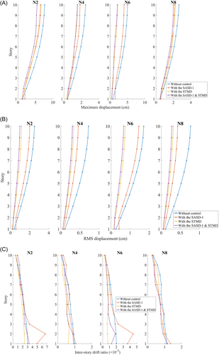
It can be seen in Figure 11 that, first, the three control cases all have a good control effect, while the proposed combination is better than with SASD or STMD acting independently; second, the STMD performs better than the SASD both in maximum and RMS responses control; third, from the perspective of base isolation, the first story where the SASD is implemented can be regarded as a special isolation layer because the story stiffness can be smaller than the regular story. From Figure 11C, it can be found that for a building with an SASD only, especially, the interstory drift ratio of the first and second floors can be larger than the case without control, while the combined use of SASD and STMD can solve this problem effectively.
To see it clearly in the time domain, take the No. 6 earthquake (Superstition Hills-02) as an example, the time history and Fourier spectrum comparisons of the top story are presented in Figure 12.

From Figure 12, the STMD can reduce structural response to a great degree, while the proposed combination can even perform better because of the contribution from SASD and they are superimposed. The enhanced earthquake protection smart structure with SASD and STMD has the best effect.
Meanwhile, under the No. 6 earthquake (Superstition Hills-02), instantaneous frequencies and damping coefficients of the STMD in these two cases are illustrated and compared in Figure 13, respectively.

It can be seen from Figure 13 that because of the addition of SASD, STMD has different variations on both instantaneous frequency and damping coefficient. It is because the STMD varies its stiffness and damping based on the output signal as introduced in Section 2. It is due to the different output signals resulting in different parameter variations.
At the same time, stiffness variation of the SASD-1 case and SASD-4 case are shown and compared in Figure 14, respectively.
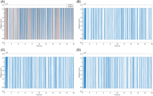
It can be seen in Figure 14 that the LQG-based variable stiffness algorithm proposed in Section 3.1 is on the basis of structural modal information and dynamic responses; therefore, stiffness variations of SASD of the two cases on the first story are different. The SASD-4 case has a significant improvement in the seismic protection performance compared to the SASD-1 case, while the combination of SASD and STMD can have a similar control effect to the SASD-4 case, while it can reduce the number of additional electromechanical systems and the influence on the use function of the building.
5 CONCLUSIONS
To reduce structural responses under earthquake excitations and improve its resilience effectively, a smart structure with an STMD on the top story and an SASD on the first story which contributes to the structural adaptive stiffness property is developed in this study. SASD consists of a diamond spring system composed of four linear springs and an electromagnetic actuator, which can change the angle of the diamond device and therefore retune the stiffness.
Two typical STMDs developed previously are reviewed first, which are diamond device-based STMD with variable stiffness and damping and pendulum-type STMD with variable frequency and eddy current damping, respectively. To enhance the seismic protection of the structure with an STMD on the top story further, based on the principle of base isolation, a diamond device-based SASD is applied to the first story. The LQG-based variable stiffness algorithm for SASD is proposed.
A 10-story building is presented as a case study. The variable stiffness range of SASD is discussed in detail, and the control effects of different numbers of SASD implemented along the height of the building are compared as well. The advantage of the combined SASD and STMD scheme in structural control is highlighted.
- 1.
The STMD can track the structural instantaneous frequency through WT and retune its stiffness, and switch its damping coefficient in real time. The STMD with variable stiffness and damping has the best vibration mitigation, and performs better than the STMD with variable stiffness or damping acting independently, because their improvements are superimposed.
- 2.
Considering the control effect as discussed, a ±50% variable stiffness range of SASD is suggested and chosen.
- 3.
With the increase in the number of SASDs, the earthquake mitigation effect is better; however, the magnitude of the increase is decreasing.
- 4.
The proposed combination of SASD and STMD has a similar control effect with four SASDs installed from the first story to the fourth story, respectively, which covers four-tenths of the floor, while the combination can reduce the number of additional electromechanical systems to save the cost, and reduce the influence on the use function of the building.
- 5.
The proposed combination is better than SASD or STMD acting independently because the contribution from them is superimposed. The enhanced earthquake protection smart structure with SASD and STMD working together has the best control effect. SASD can reduce the energy input by changing the stiffness of the structure in real time, while STMD will maximize the absorbed structural kinetic energy and dissipate it for a better earthquake mitigation performance.
In this study, only a linear tall building is considered. Nonlinear structures and residual interstory drift ratio will be investigated in further research.
ACKNOWLEDGMENTS
The authors are grateful for the financial support received from the National Natural Science Foundation of China (Grant No. 52025083), the National Key Research and Development Program of China (Grant No. 2022YFF0608903), and this study is also sponsored by Shanghai Pujiang Program (22PJ1413600) and supported by the Fundamental Research Funds for the Central Universities (22120220573).
CONFLICTS OF INTEREST STATEMENT
The authors declare no conflicts of interest.


