Uniform Metal Sulfide@N-doped Carbon Nanospheres for Sodium Storage: Universal Synthesis Strategy and Superior Performance
Abstract
Nitrogen-doped carbon-coated transition-metal sulfides (TMS@NCs) have been considered as efficient anodes for sodium-ion batteries. However, the uncontrollable morphology and weak core–shell binding forces significantly limit the sodium storage performance and life. Herein, based on the reversible ring-opening reaction of the epoxy group of the tertiary amino group-rich epoxide cationic polyacrylamide (ECP) at the beginning of hydrothermal process (acidic environment) and the irreversible ring-opening (cross-linking reactions) at the late hydrothermal period (alkaline environment), 47 nm-sized ZnS@NCs were prepared via a one-pot hydrothermal process. During this process, the covalent bonds formed between the ZnS core and elastic carbon shell significantly improved the mechanical and chemical stabilities of ZnS@NC. Benefiting from the nanosize, fast ion/electron transfer, and high stability, ZnS@NC exhibited a high reversible capacity of 421.9 mAh g−1 at a current density of 0.1 A g−1 after 1000 cycles and a superior rate capability of 273.8 mAh g−1 at a current density of 5 A g−1. Moreover, via this universal synthesis strategy, a series of TMS@NCs, such as MoS2@NC, NiS@NC, and CuS@NC were developed with excellent capacity and cyclability.
1 Introduction
Sodium-ion batteries (SIBs) have been considered as an alternative power source to lithium-ion batteries because of their low price, abundant resources, and wide distribution. However, during cycling, the large radius of Na+ contributes to the sluggish kinetics of ions and a large volume change of active materials, resulting in a low theoretical capacity and running life of the electrodes.[1-3] Therefore, there is an urgency to develop suitable host materials with fast ion-transport kinetics and improved cycling stability. Transition-metal sulfides (TMSs) such as ZnS, MoS2, CuS, and NiS,[4-7] have been employed as electrode materials for lithium-ion, sodium-ion, and zinc-ion batteries as well as supercapacitors, because of their high theoretical capacity, layered structures, and excellent chemical activity.[8] However, pure TMS faces the challenges of poor electronic and ionic conductivities, and large volume changes, resulting in a lower capacity, cycle performance retention rate, and rate capacity of the battery, along with poor mechanical and chemical stabilities.
To overcome these challenges, common strategies aim to nanocrystallize TMS and introduce conductive carbon additives to form TMS/C nanocomposites to shorten the ion diffusion distance, increase the electronic conductivity, and inhibit the volume change of the active material. This will enhance the utilization efficiency and charge transfer dynamics of the electrode and lead to an improved capacity, rate performance, and cycle life of the battery.[9, 10] Compared with the carbon conductive additive mode, the N-doped carbon-coated TMS (TMS@NC), which encapsulates the active nanoparticles in conductive shells to form a close core–shell structure, is optimal, especially in the inhibition of the volume expansion of TMSs. The closely bonded carbon shell provides not only an effective conductive path to improve the overall electrical conductivity of the electrode, but also a stable framework that prevents the TMS from pulverization caused by the volume expansion under long-term ion stripping/plating cycling.[11]
At present, the common synthesis methods for core–shell structured composites, such as Ni3S2@NC,[12] ZnS@NC,[13] and CuS@NC,[14] include organic coating,[11] CVD deposition,[15] detonation,[16] hydro-thermal methods,[17] etc. Although the use of these methods results in the controlled growth of the carbon shell with exact and uniform thickness, pure TMS had to be synthesized in advance to act as the base of the carbon coating. It is worth mentioning that the morphology of the final TMS@NC products is highly dependent on the size and uniformity of the TMS precursors. Additionally, during the carbon coating process, considering the hydrothermal reaction, the high-temperature environment could cause the agglomeration of TMS nanoparticles and lead to an uncontrollable morphology of TMS@NC.[15] Therefore, along with new chemical engineering strategies, it is an essential necessity to design a simple, efficient, and controllable technique to synthesize uniformly nanosized TMS@NCs as active electrode materials for batteries.
For nanoparticle synthesis, the emulsifier generally has a low molecular weight (Mw < 50 000), which is beneficial for obtaining nanosized TMS cores, but is not a viable carbon source due to the low residual carbon rate. Although increasing the molecular weight (Mw > 1 000 000) is beneficial for forming the carbon shell with a high carbon residue rate, it results in a poor emulsification ability.[18] In order to benefit from both the advantages, the amphiphilic epoxide cationic polyacrylamide (ECP) (Figure S1, Supporting Information) with hydrophilic quaternary ammonium groups and hydrophobic carbon chains was designed to synthesize TMS@NC nanospheres as an ideal emulgator and carbon source. Herein, at the beginning of the synthesis, owing to the suitable molecular weight (Mw = 26 964) (Figure S2a, Supporting Information), ECP as a surfactant possessed efficient emulsification capabilities for oil-in-water (O/W) type micelles, which reduced the surface energy of the primary TMS seed to prevent its aggregation. In the later stage, after chemical cross-linking, the ECPs with the high ring tension epoxy and hydroxymethyl as the primary and secondary cross-linking functional groups, respectively, formed a rigid three-dimensional network structure with high carbon content and high molecular chain cohesion, resulting in a high residual carbon rate and high carbon structure strength after carbonization for the carbon shell.[19] Moreover, the acrylamide and quaternary ammonium groups provided a prerequisite for the formation of nitrogen-doped carbon.
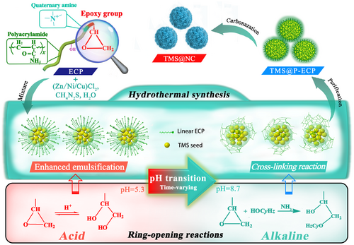
Herein, based on the different ring-opening reactions of the epoxy group in ECP at different pH values, a series of TMS@NC nanospheres, such as ZnS@NC, MoS2@NC, NiS@NC, and CuS@NC, were developed via a universal one-pot hydrothermal reaction process (Scheme 1). Specifically, the epoxy group changed to two hydroxyl groups in the initial acidic hydrothermal environment via a reversible ring-opening reaction, which further reduced the size and stabilized the structure of the nanoscale O/W micelles. As the synthesis reaction progressed, ammonia as a by-product caused the reaction solution to become alkaline. In an alkaline environment, an irreversible ring-opening reaction of the epoxy groups, as the main cross-linking reaction, formed a layer of P-ECP, closely coated on the TMS surface in situ. After carbonization, the uniform nanosize and core–shell structure linked by covalent bonds of the TMS@NC nanospheres ensured effective conductivity and stability, which formed the structural foundation for promising sodium storage performance with excellent capacity and stability.
2 Results and Discussion
2.1 Synthesis Mechanism and Characterization of ZnS@NC Nanospheres
ZnS@NC was employed as a model material to illustrate the formation mechanism of the TMS@NCs. First, as shown in Figure S3a, Supporting Information, the emulsification effect is the key factor affecting the uniformity and nanoscale formation of the ZnS particles. When the ECP amount was greater than its critical micelle concentration value (1.149 g L−1) (Figure S2b, Supporting Information), the hydrophilic groups such as quaternary amino groups in ECP extended outward to form the outer layer of the micelle. The hydrophobic carbon chains were closely arranged by van der Waals forces to form the inner core of the micelle, resulting in the autonomous formation of O/W micelles of ECP. Specifically, the lipophilic primary ZnS seed, formed by the covalent bonding of zinc (from ZnCl2) and sulfur (from thiourea), was captured by the O/W micelles entering the micellar oil phase. Owing to the high surface energy, the seeds inside the micelle annexed to each other to balance the emulsifying ability and surface energy. Meanwhile, micelles also annexed to each other until an equilibrium was achieved between the surface energy and electrostatic repulsion of the micelle,[20] which restricted the free growth of micelles to ensure uniformity in the nano-growth of ZnS. Notably, the epoxy group in ECP played a special role in enhancing the formation of micelles. In the initial stages of the hydrothermal reaction, the aqueous solution was acidic (pH = 5.2), owing to the strong acid and weak base salt of ZnCl2. Figure S3c, Supporting Information, in the ESI shows that the acid promoted protonation of the epoxy group in ECP. Subsequently, H2O as a nucleophile attacked the central carbon atom of the epoxy group to break the C−O bond and form a reversible dihydroxy compound.[21] The resulting dihydroxy compound inhibited the cross-linking activity of the epoxy group and enhanced its initial emulsification ability. Specifically, the strong hydrophilicity and polarity of dihydroxy groups increased the electron cloud density difference inside and outside the micelle to enhance the O/W micelle stability (Table S1, Supporting Information) and resulted in a small micelle size of 8.9 nm (Figure S2c, Supporting Information).
The formation process of the organics-coated nano-ZnS particles is shown in Figure S3b, Supporting Information. In the hydrothermal reaction process, NH3 (by-product of thiourea hydrolysis) gradually changed the solution pH from acidic to neutral, thus prompting the acidic ring-opening dihydroxy group to close and return to an epoxy group with cross-linking activity. Subsequently, the solution became weakly alkaline (pH = 8.7) with the continued release of NH3, and this led to the irreversible ring-opening reaction of the epoxy group. Comprehensively, NH3 was the driving force for the irreversible ring-opening owing to it having no-bonding lone pairs and attacking the central carbon atom of the epoxy group as a strong nucleophile.[21] This promoted the cross-linking among linear ECP molecules to form an insoluble network-polymerized ECP (P-ECP)-coated ZnS through a more stable ether bond. To determine the function of ECP, Fourier transform infrared spectroscopic tests (Figure S4, Supporting Information) were performed to demonstrate the chemical changes during the cross-linking step. ECP and ZnS@P-ECP exhibited similar characteristic absorption peaks of −CH3 (stretching vibration peak at 2 930 cm−1 and bending vibration peak at 1 390 cm−1), −CH2 (stretching vibration peak at 2 862 cm−1 and bending vibration peak at 1 460 cm−1), −COO− (stretching vibration peak at 1 740 cm−1), and −CO−N (stretching vibration peak at 1 670 cm−1). It is noteworthy that, compared with ECP, ZnS@P-ECP shows a weakened hydroxyl (−OH) (stretching vibration absorption peak at 3 337 cm−1) and an enhanced ether bond (C–O–C) (stretching vibration absorption peak at 1 217 cm−1) signal. Because the epoxy group in ECP underwent an alkaline ring-opening reaction in an alkaline hydrothermal environment, the ECP molecule was condensed and dehydrated to form P-ECP with a more stable ether bond.[21] Finally, in the carbonization process, the non-bonding lone pairs of S in ZnS formed covalent bonds with the rearranged C element to obtain the ZnS@NC nanospheres with a C−S covalent bond-connected core–shell structure.
A series of basic physical analyses were carried out to reveal the characteristics of the ZnS@NC nanospheres. Generally, as shown in Figure 1a and Figure S5, Supporting Information, the pure ZnS prepared without ECP exhibits randomly distributed particles sizes ranging from 50 nm to 2 μm, and a clear crystal structure with d-spacings of 0.308 ((111) plane), 0.188 ((220) plane), and 0.161 nm ((311) plane) (Figure S6, Supporting Information), without a carbon coating. After employing ECP, uniformly sized (~ 50 nm) ZnS@P-ECP nanospheres coated with an even layer of P-ECP, having a thickness of 3 – 5 nm (Figure 1b) and a uniform and abundant distribution of nitrogen components (Figure S7, Supporting Information), were successfully acquired in the form of aggregates. After carbonization, the ZnS@NC particles were predominantly independent, uniformly sized (47.4 ± 3.3 nm), and N-doped carbon-coated ZnS nanospheres with a closed carbon shell of ~2.2 nm in thickness and 0.352 nm in lattice spacing (Figure 1c and Figure S8, Supporting Information). The reduction in the carbon coating thickness and the nanosphere separation in ZnS@NC are mainly due to the molecular shrinkage, transformation, functional group removal, and increase in the degree of carbon crystallization in P-ECP. The elemental mapping and thermogravimetric analysis of ZnS@NC revealed uniform distributions of C, N, Zn, and S elements (Figure S8e,f, Supporting Information) and a carbon content of 16.4 wt% (Figure S9a, Supporting Information). Using the above carbon content value as the standard, ZnS@NC particles with carbon shells of various thicknesses were prepared (Figure S9b, Supporting Information) by adjusting the ECP quantity to reveal the influence mechanism of the carbon content on the morphology of the ZnS@NC nanospheres. With a reduction in the ECP content, ZnS@NC(5.3 wt% in carbon content) (Figure S10a−c, Supporting Information) exhibits a wide range of particle sizes from 50 nm to 3 μm, due to the lack of sufficient micelles to wrap all the seeds during the ZnS seed formation, causing an uncontrolled growth of this part of the ZnS seeds. With an excess of ECP, even the thickness of the carbon shell increased to 5 – 9 nm (Figure S9d−f, Supporting Information), owing to the excess P-ECP agglomerate on the ZnS surface. The size of the resulting ZnS@NC (20.4 wt% in carbon content) nanospheres was still less than 50 nm, which was consistent with that of the prior 16.4 wt% sample.
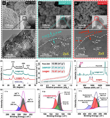
All X-ray diffraction patterns (Figure 1d) of pure ZnS, ZnS@P-ECP, and ZnS@NC exhibited three peaks at 28.6°, 47.8°, and 56.7°, corresponding to the (111), (220), and (311) crystal planes of ZnS, respectively.[22] Compared with the sharp (111) peak of pure ZnS, the wider (111) peaks of ZnS@P-ECP and ZnS@NC were mainly due to the reduction in the crystal size of ZnS.[23] The reduced particle size ultimately means an increased specific surface area. As shown in Figure 1e, the ZnS@NC particles exhibit an approximately seven times larger surface area (70.97 m2 g−1) compared to that of pure ZnS (10.99 m2 g−1), and a micropore distribution of 3 – 4 nm (Figure S11, Supporting Information), unlike pure ZnS and ZnS@P-ECP. The porous and high specific surface area structures of ZnS@NC not only provided ion pathways for Na+ diffusion in the electrode, but also increased the contact area between the electrode and the electrolyte, resulting in fast transport kinetics and improved sodium storage and rate performance.[24]
The Raman spectra (Figure 1f) reveals that the two strong peaks at 260.3 and 356.8 cm−1 are the characteristic peaks of ZnS, and the two characteristic peaks located at 1 355 and 1 589 cm−1 correspond to the D-zone disordered mode (non-graphitic structure) and G-zone stretching mode (graphitic structure) of carbon. After carbonization, the vanishing peaks in ZnS@P-ECP and the enhanced D-bond/G-bond (ID/IG) ratio in ZnS@NC can be seen as follows: during the carbonization process at high temperatures, decomposition of the functional groups (C−H at 2 930 cm−1, −COO− at 1 650 cm−1, −C−O−C at 1 097 cm−1, etc.) in ZnS@P-ECP and crystallization of the carbon shell led to a high degree of graphitization of the carbon shell in ZnS@NC, that is, the ID/IG ratio was about 1.0, which forms the structural basis for high electronic conductivity.[23]
The X-ray photoelectron spectroscopy peaks of C 1 s at 284.4, 284.9, and 286.1 eV spectrums for ZnS@NC (Figure S12, Supporting Information) correspond to sp2 carbon, sp3 carbon, and C−O groups, respectively. As shown in Figure 1g, the atomic content ratio of sp2 C and sp3 C is approximately 3:5. Originating from the out-of-plane flexibility of the sp2 bond, the high content of sp2 C ensures that the carbon shell has sufficient elasticity to restrain the expansion of ZnS@NC under long-term cycling of the battery.[25, 26] Moreover, the high-resolution S 2p spectrum in Figure 1h reveals not only two chemical bonding states of S2− at 161.2 and 161.8 eV in the Zn-S bond structure, but also the peak at 162.4 eV, which demonstrates that the ZnS core was linked to the carbon shell by covalent bonds, ensuring uniform mechanical stability of the core–shell structure during the cycle. This covalent bond was formed by sharing electrons (effective overlap of atomic orbitals) between the sulfur element containing lone pairs as the nucleophile and the unstable carbon element as the electrophile, during the rearrangement of the carbonized carbon components in the high-temperature carbonization step. As for the N-doping in the carbon shell, Figure 1i reveals that the N 1s spectrum includes four types of nitrogen: pyridine-N (398.6 eV), pyridine-N-oxide (402.2 eV), pyrrole-N (399.3 eV), and quaternary-N (400.0 eV). Among them, quaternary-N can reduce the interface impedance and increase the conductivity of carbon materials to improve the rate performance of composite materials. Pyridine-N is conducive to Na-ion storage to improve the reversible capacity.[27] Therefore, the uniform core–shell structured ZnS@NC nanospheres with a stable and highly elastic carbon are an ideal anode material for batteries (Figure S13, Supporting Information).
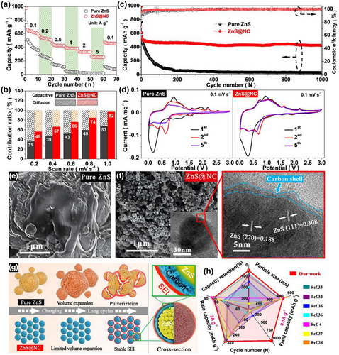
The long-term cycling data, as shown in Figure 2c, include two periods: activation and running. Figure S16, Supporting Information, shows that during the activation step of the first five cycles, the ZnS@NC anode delivered a higher initial discharge capacity of 992.3 mAh g−1 with a better initial Coulombic efficiency of 72.9% than that of the pure ZnS anode (initial discharge capacity of 766.9 mAh g−1, Coulombic efficiency of 60.5%). Considering the sodiation/desodiation mechanism, as shown in the cyclic voltammetry profiles of Figure 2d, the strong reduction peak at 0.2 V in the 1st cycle observed on both the ZnS and ZnS@NC anodes disappeared in subsequent scans, which links to the formation of a solid electrolyte interface (SEI) layer.[4, 31] The peaks at 0.30, 0.61, 1.15, 1.60, and 1.94 V, in subsequent cycles, corresponding to the multiple steps of the dealloying process to Na2S and the insertion of Na+ into ZnS crystal,[4] which were further evidenced in Figure S17, Supporting Information. It is noteworthy that the redox peaks of the ZnS@NC anode overlapped at the 2nd and 5th cycles, unlike the pure ZnS anode, where the redox peaks at 1.60 and 1.94 V disappeared at the 5th cycle, which indicates the good reversibility of the ZnS@NC anode in Na-ion storage. In detail, after five cycles, the irreversible volume pulverization of pure ZnS particles with irregularly large size (>1 μm) resulted in the excessive formation of SEI layer and the gradual decrease in the reactivity efficiency of the ZnS electrode, which in turn caused the rapid decrease in the redox peaks on the CV curve. In contrast, the ZnS@NC electrode exhibited higher redox peak intensity retention in Figure 2d than the pure ZnS electrode, due to the highly elastic outer carbon layer of ZnS@NC suppressing the volume expansion during charging-discharging processes, meaning that a stable SEI layer has been formed in the ZnS@NC electrode and promoted the electrode into a stable charge–discharge process.
During the long-term running step, a significant decay occurred in the pure ZnS anode during the first 200 cycles until the capacity dropped to 51.5 mAh g−1 with a low average Coulombic efficiency of 96.3% and a low-capacity retention of 6.7%. In contrast, even after 1 000 cycles, the ZnS@NC anode still provided a high reversible discharge capacity of 421.9 mAh g−1, a high average Coulombic efficiency of 99.4%, and a high-capacity retention of 83.1%. Considering the performance stability difference, the scanning electron microscopy (SEM) images of the pure ZnS (Figure 2e) and ZnS@NC (Figure 2f and Figure S18, Supporting Information) anodes after 1000 cycles visually verified that, unlike pure ZnS, which was pulverized and aggregated into irregular blocks, ZnS@NC particles remained a nanosphere of ~50 nm size and retained a complete core–shell structure, which indicates that the excellent long-term running performance of ZnS@NC was attributed to the tight carbon shell and its strong bonding force with the ZnS core.
Furthermore, as shown in the electrochemical impedance spectroscopy (Figure S19, Supporting Information), at the 5th cycle, ZnS@NC shows a much lower charge transfer resistance (Rct) at the electrode–electrolyte interface than pure ZnS, revealing that through the activation process, a stable SEI layer was rapidly constructed on the ZnS@NC surface by means of more active sites and an excellent electron transport pathway of the N-doped carbon shell. This avoided the excessive formation of an SEI layer on the surface of the active substance, similar to pure ZnS (Figure 2g). It has been reported that, compared with hard carbon layers, the SEI layer is more stable on the surface of the disordered carbon layer due to the relieved volume expansion caused by its certain elasticity.[32] After 500 cycles, the impedance of ZnS@NC was still less than that of pure ZnS, indicating that the elastic carbon shell and the C−S covalent bond played an important role in slowing down the volume expansion and charge transfer resistance of the anode during the sodiation/desodiation process to ensure structural stability and integrity without cracking during long-term cycling. Compared with the previously reported ZnS anodes in SIBs (Figure 2h),[33-38] ZnS@NC possesses competitive advantages considering the nanometer scale of the TMS particles, improved rate performance, discharge capacity, capacity retention, and cycle life. Correspondingly, under competitive current densities of 0.1 A g−1 and 2.0 A g−1, ZnS@NC shows the highest capacities of 421.9 mAh g−1 and 331.6 mAh g−1, respectively, while having a small particle size (47 nm). Meanwhile, the assembled ZnS@NC//NVPOF full cell exhibits a stable reversible discharge capacity of 238.8 mAh g−1 after 100 cycles at current density of 0.1 A g−1 (Figures S20 and S21, Supporting Information), which is a further evidence to support ZnS@NC as high-performance anode for Na-ion batteries.
2.2 Validation of the Universal Synthesis Strategy
To verify the general applicability of this synthesis method, more TMS@NCs, such as MoS2@NC, NiS@NC, and CuS@NC, were prepared and analyzed systematically, as shown in Figure 3 and Figure S22, Supporting Information. For the pure MoS2 (Figure S23a,b, Supporting Information), NiS (Figure S24a,b, Supporting Information), and CuS (Figure S25a,b, Supporting Information) materials, the particle sizes were random with a wide size distribution ranging from 500 nm to 3 μm. In contrast, benefiting from the functional adjustment of ECP, CuS@NC exhibited regular spherical particles with a size of approximately 500 nm (Figure 3i,j and Figure S25c, Supporting Information); NiS@NC was composed of irregular polygonal particles with a size of approximately 10 nm (Figure 3e,f and Figure S24c, Supporting Information); and the MoS2@NC particles were in the shape of flower clusters with a size of 200 nm (Figure 3a,b and Figure S23c, Supporting Information). The difference in the particle sizes of the TMS@NCs was mainly caused by the difference in the surface energy of the primary seeds.[39-41] For all the TMS@NCs, after the hydrothermal process, the weakened hydroxyl absorption peak (3 330 cm−1) and the relatively stronger ether bond absorption peak (1 210 cm−1) was consistent with the synthesis of ZnS@NC, that is, the alkaline ring-opening reaction of ECP occurred successfully. The TEM and EDS mapping of the TMS@NCs confirmed that the outer carbon shell with uniformly distributed N and C was evenly distributed on the TMS surface (Figure 3c,g,k). The uniformly distributed structure and particle sizes fully illustrate the size adjustment function of ECP and the tightly closed carbon shell structure.
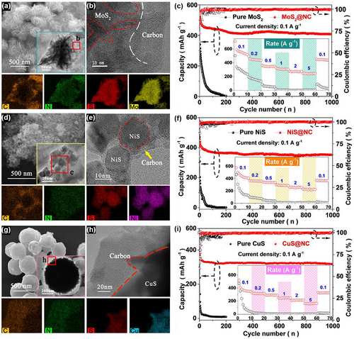
Likewise, the ID/IG values calculated from the Raman spectrum were 1.2, 1.1, and 0.9 for MoS2@NC (Figure S22b, Supporting Information), NiS@NC (Figure S22e, Supporting Information), and CuS@NC (Figure S22h, Supporting Information), respectively, suggesting a certain degree of graphitic structure which improves conductivity for all the TMS@NCs. Also, the specific surface areas (Figure S26, Supporting Information) of MoS2@NC (39.3 m2 g−1), NiS@NC (16.2 m2 g−1), and CuS@NC (21.5 m2 g−1) were correspondingly higher than that of the pure TMSs, which provides sufficient active sites for sodiation/desodiation during cycling. Compared with the pure TMSs, the TMS@NCs such as CuS@NC, NiS@NC, and MoS2@NC exhibited higher contribution of pseudo-capacitances of 81%, 88%, and 75%, respectively (Figure S27, Supporting Information), and higher capacities of 319.7 mAh g−1 (Figure 3i), 352.3 mAh g−1 (Figure 3h), and 408.3 mAh g−1 (Figure 3e), respectively, after 1000 cycles at a current density of 0.1 A g−1. The electrochemical impedance (Figure S28, Supporting Information) indicates that the Rct of TMS@NCs is lower than that of the pure TMSs, which promotes the excellent cycle performance of TMS@NC in SIBs, benefiting from the nanosized core–shell structure of TMS@NC and high charge conductivity of the elastic nitrogen-doped carbon shell. Compared with the previously reported MoS2 (Table S2, Supporting Information), MoS2@NC has a competitive advantage in terms of capacity, rate performance, and cycle life for SIBs. These nano-electrode materials developed using this universal synthesis strategy could be applied to a wide range of secondary batteries, such as lithium-ion and zinc-ion batteries.
3 Conclusion
In this study, based on the reversible ring-opening reaction in acidic conditions and the irreversible ring-opening cross-linking reaction in an alkaline environment of the epoxy group of the tertiary amino group-rich ECP, 47 nm-sized N-doped carbon-coated ZnS nanospheres were prepared via a simple one-pot hydrothermal synthesis process. At the beginning of the hydrothermal reaction, the aqueous synthesis solution was acidic (pH = 5.2), owing to the strong acid and weak base salt of ZnCl2. In an acidic environment, the reversible ring-opening reaction of the epoxy group under acidic conditions enhanced oil-in-water micelles and realized the formation of homogeneous ZnS nanospheres. As the synthesis progressed, the solution became weakly alkaline (pH = 8.7) with the continued release of NH3 as a by-product. The irreversible cross-linking reaction of the epoxy group, with the carbonization treatment, caused an elastic N-doped carbon shell to form on the surface of ZnS nanospheres with C−S covalent bonds between the ZnS core and carbon shell. Benefiting from the nanosize, fast charge transfer, and stable core–shell structure, ZnS@NC exhibited a high reversible capacity of 421.9 mAh g−1 at 0.1 A g−1 current density after 1000 cycles and a superior rate capability of 273.8 mAh g−1 at 5 A g−1 current density. Moreover, via this universal synthesis strategy, a series of TMS@NCs such as MoS2@NC, NiS@NC, and CuS@NC, were developed with excellent capacities of 408.3 mAh g−1, 352.3 mAh g−1, and 319.7 mAh g−1, respectively, at 0.1 A g−1 current density after 1000 cycles.
Acknowledgements
K.Y. and H.F. contributed equally to this work. This work was supported by research grants from the National Research Foundation of Korea (Nos. 2020R1I1A1A01072996, 2021K2A9A2A06044652, and 2019H1D3A1A01069779) and KIST Institutional Program (2E331863) funded by the government of the Republic of Korea.
Conflict of Interest
The authors declare no conflict of interest.
Author Contributions
G. L., K. Y., and H. F. conceived and designed the study. K. Y. and H. F. conducted the experiments and wrote the initial draft. Y. D. and M. W. performed the battery assembly and SEM characterization. M. X. T. performed TEM analysis. G. L. (Lead contact), W. Y., and J. K. L. supervised the project. All authors have commented on the manuscript.


