All-Climate Stretchable Dendrite-Free Zn-Ion Hybrid Supercapacitors Enabled by Hydrogel Electrolyte Engineering
Abstract
Hybrid supercapacitors have shown great potentials to fulfill the demand of future diverse applications such as electric vehicles and portable/wearable electronics. In particular, aqueous zinc-ion hybrid supercapacitors (ZHSCs) have gained much attention due to their low-cost, high energy density, and environmental friendliness. Nevertheless, typical ZHSCs use Zn metal anode and normal liquid electrolyte, causing the dendrite issue, restricted working temperature, and inferior device flexibility. Herein, a novel flexible Zn-ion hybrid supercapacitor (FZHSC) is developed by using activated carbon (AC) anode, δ-MnO2 cathode, and innovative PVA-based gel electrolyte. In this design, heavy Zn anode and its dendrite issue are avoided and layered cathode with large interlayer spacing is employed. In addition, flexible electrodes are prepared and integrated with an anti-freezing, stretchable, and compressible hydrogel electrolyte, which is attained by simultaneously using glycerol additive and freezing/thawing technique to regulate the hydrogen bond and microstructure. The resulting FZHSC exhibits good rate capability, high energy density (47.86 Wh kg−1; 3.94 mWh cm−3), high power density (5.81 kW kg−1; 480 mW cm−3), and excellent cycling stability (~91% capacity retention after 30 000 cycles). Furthermore, our FZHSC demonstrates outstanding flexibility with capacitance almost unchanged even after various continuous shape deformations. The hydrogel electrolyte still maintains high ionic conductivity at ultralow temperatures (≤−30°C), enabling the FZHSC cycled well, and powering electronic timer robustly within an all-climate temperature range of −30~80°C. This work highlights that the promising Zn metal-free aqueous ZHSCs can be designed with great multifunctionality for more practical application scenarios.
1 Introduction
Due to the fast development of hybrid and pure electric vehicles and portable/wearable electronic devices, advanced energy storage systems with high power, high energy, and good safety are particularly demanded.[1] Hybrid supercapacitors (HSCs), which consist of a capacitive electrode and a battery-type electrode, have shown great potentials to fulfill the above requirements.[2-5] In particular, using aqueous electrolytes instead of conventional organic electrolytes can further enable a greener and safer aqueous HSCs. On the contrary, choosing multivalent ions as energy carriers generally increases the number of electrons involved in the reaction, thus, in principle, leading to higher energy density. As a consequence, aqueous multivalent ion HSCs have attracted increasing attention in recent few years.[6-8]
To date, various multivalent ion energy storage devices and charge storage mechanisms have been investigated.[9-11] Among them, zinc-ion-based aqueous devices show great promise due to rich zinc resources, environmental friendliness, good reversibility, and high specific capacity.[12-14] There have been two kinds of Zn-ion hybrid capacitors (ZHSCs) developed, as illustrated in Figure 1a. Type I was widely reported in recent years (Table S1) by taking the advantage of the high theoretical capacity of Zn metal anode.[15, 16] However, one of the main issues for Zn anode is the growth of dendrites, especially at high rates that are required for supercapacitors; in the meantime, self-corrosion and passivation of Zn anode generally occur, leading to poor lifetime or even electrode failure.[17] The conversion reaction of Zn gives large capacity but slow kinetics, which also causes problems in specific capacity and kinetics mismatching with the capacitive cathode. In addition, the use of excess Zn will definitely increase the total weight and thus reduce the energy density at the device level. To avoid these intrinsic shortcomings, Type II ZHSCs were reported.[18, 19] In this device design, capacitive material rather than Zn is generally chosen as the anode while the cathode is material that can host Zn2+ via ion insertion; the difference in specific capacity between two electrodes is thus reduced. Selection of appropriate host cathode materials with direct and fast ion insertion will further reduce the kinetics difference from the anode. Besides, Zn dendrites can be readily avoided by tuning the anode potential window. Despite some progress in Type II ZHSCs (Table S1),[18, 20] the typically used electrolyte was conventional solution of Zn salts. However, liquid electrolyte has the intrinsic risk of leakage, high freezing points, and low boiling points, which limit their all-climate practical operation.[21-23] For future emerging applications in flexible and wearable electronics,[24-26] it is highly necessary to develop all-climate high-performance (quasi-)solid-state ZHSCs, which are expected to not only provide high energy and power, but also meet the fundamental criterions of long duration, good adaption to serious climate change, and excellent stress tolerance.
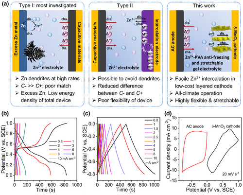
Herein, we report on an advanced wide-temperature range quasi-solid-state flexible ZHSC (FZHSC) by introducing poly(vinyl alcohol) (PVA)-based innovative hydrogel electrolyte into Type II ZHSC. Layered δ-MnO2 that can ensure the direct and stable Zn2+ insertion without phase transformation and commercial activated carbon (AC) with the state-of-the-art capacitive ability,[9] are respectively selected as cathode and anode materials to manifest the intrinsic merits of Type II ZHSC. PVA is employed as the polymer substrate to synthesize gel electrolyte, which is cheap, nontoxic, non-corrosive, easy to process into film with excellent flexibility, and has good ability to dissolve salt.[27, 28] To achieve the device multifunctionality, glycerol (GL) additive and freezing/thawing technique are utilized together to design the gel electrolyte for the first time. GL is found to not only inhibit H2O freezing, but also generate intermolecular and intramolecular hydrogen bond with polymers and H2O, promoting the flexibility. In the meantime, the freezing/thawing process promotes the generation of crosslinked gel electrolyte with PVA microcrystalline located at the intersection point, significantly boosting the thermal stability and mechanical properties. Consequently, the PVA-based gel electrolyte demonstrates ultralow freezing point (−105.73 °C) and outstanding compressibility and stretchability.
As anticipated, our assembled Type II ZHSC simultaneously exhibits high energy density (47.86 Wh kg−1; 3.94 mWh cm−3), high power density (5.81 kW kg−1; 0.48 W cm−3), and excellent cycling stability (~91% capacity retention after 30 000 cycles), highlighting the importance of cathode and anode pairing. Furthermore, the novel FZHSC shows outstanding flexibility (capacitance almost unchanged even after various successive shape deformations) and even good stretchability that were not demonstrated in previous Type II ZHSCs and can be easily connected in series or in parallel with good electrochemical attributes. Finally, the FZHSC still cycles well over a broad temperature range of −30~80 °C, highlighting great potential for wearable electronics application in high-temperature and extremely cold environments.
2 Results and Discussion
δ-MnO2 has an intrinsic structure with the interlayer spacing of ≈7 Å and exhibits high storage capacity of Zn2+ ions. In particular, it can undergo a beneficial “layered to layered” structural evolution during Zn2+ intercalation and de-intercalation, as revealed in our recent work on aqueous Zn-Mn batteries.[9] Such an energetically and kinetically favorable Zn2+ storage process makes δ-MnO2 very promising as cathode material for ZHSC in the present work. Figure S1a and its inset show the scanning electron microscopy (SEM) image and typical optical picture of the as-prepared δ-MnO2 cathode film. Numer-ous thin MnO2 nanoflakes are evenly grown on stainless steel (SS) substrate and interconnected with each other, presenting a continuous three-dimensional (3D) architecture. The whole cathode is quite flexible and can be readily bent for many times. High-resolution transmission electron microscopy (HRTEM) image in Figure S1b demonstrates the layered crystal structure and the tiny thickness of about several nanometers. X-ray diffraction (XRD) pattern (Figure S1c) and X-ray photoelectron spectroscopy (XPS) spectra (Figure S1d) further confirm the composition of the deposited film is δ-MnO2 (JCPDS card No. 18-802).
Electrochemical performances of the δ-MnO2 cathode and AC anode were investigated by using a typical three-electrode system. Cyclic voltammetry (CV) curves at different scan rates were firstly recorded to identify the electrochemical reaction mechanisms. Figure S2a displays the CV profiles of δ-MnO2 cathode. The cathodic peaks at around 0.35 V correspond to the reduction reaction from Mn4+ to Mn3+ associated with Zn2+ insertion into δ-MnO2 layer, and the anodic peaks at approximately 0.6 V correspond to the oxidation of Mn3+ to Mn4+ upon Zn2+ de-insertion.[9] The obvious plateaus in galvanostatic charge–discharge (GCD) curves collected at different current densities also identify the battery-type redox reactions (Figure 1b). Note that the δ-MnO2 cathode always shows high coulombic efficiencies at different current densities (Figure S2b), indicating good reversibility of Zn2+ intercalation chemistry in δ-MnO2. Electrochemical performances of AC anode are further shown in Figure S3. Considering that Zn plating may occur at much lower discharge potentials, various potential windows for AC anode were comparatively tested to determine the optimal working potential range (Figure S3a,b). It was clearly observed that extending the negative potential beyond −0.8 V resulted in serious hydrogen evolution and Zn plating, together with much reduced coulombic efficiencies (Figure S3c). The coulombic efficiency with the negative cut-off potential of −0.9 V is only ~85.69%. Therefore, the AC anode was finally cycled within −0.8~0 V versus saturated calomel electrode (SCE) (Figure S3d), which always presents obvious rectangular CV profiles at different scan rates. As further seen from XRD patterns in Figure S3e, there are no obvious Zn signals after discharging, which proves that Zn plating can be ignored when cycling the anode within −0.8~0 V. The GCD curves also demonstrate a linear relationship with discharge potential versus time (Figure 1c), characteristic of typical electric double layer capacitive (EDLC) behavior. To effectively assemble ZHSCs, we matched the cathode and anode based on the charges stored per gram at 5 mA cm−2, and the mass ratio of cathode material to anode material was set to 1: 7.8. Figure 1d illustrates CV curves of both the AC anode and δ-MnO2 cathode at 20 mV s−1, indicating a possible broad voltage window (~1.8 V) of the ZHSC. The calculated stored charges of the two electrodes are comparable (153.61 and 185.31 mC cm−2), indicative of good charge balance.
Different from previous reports on Type II ZHSCs using liquid electrolytes, we next firstly place our focus on designing a quasi-solid-state Type II FZHSC device by employing a PVA-ZnSO4-based gel as the electrolyte (Figure 2a). It is worth noting that, from the CV and GCD profiles of the gel device, the electrochemical behavior shows no difference from that of the liquid electrolyte (Figure 2b and Figure S4). CVs in Figure 2b reveal that the FZHSC can be well discharged and charged within the voltage range of 0–1.8 V. The shapes of these CVs are evidently different from those of AC//AC symmetric supercapacitors and Zn//MnO2 batteries,[9] demonstrating a hybrid behavior with a distorted rectangular shape and very broad redox peaks. The GCD testing (Figure S4) was applied to measure the capacity, energy density, and power density of the FZHSC device. For comparison, electrochemical data from ZHSC using liquid electrolyte were also measured. The rate performance of devices was firstly given in Figure 2c. It is found that our FZHSC shows similar rate capability to the device using liquid electrolyte, which can be attributed to the 3D intimate contact between gel electrolyte and electrode. Although the specific capacitance of the FZHSC at each current density is slightly smaller than the liquid ZHSC probably due to the reduced interfacial contact between gel electrolyte and electrode, the rate retention ability is comparable. For our FZHSC, specific capacitance (based on the mass of both cathode and anode active materials) of 22 F g−1 can be obtained at high current density of 10 mA cm−2, which is still ~ 41.36% of the initial capacitance at 1 mA cm−2 (53.18 F g−1).

The energy density and power density of our FZHSC were further calculated and compared with other reported electrochemical energy storage devices, as illustrated in Figure 2d. Considering the total mass of active materials in cathode and anode, our FZHSC device delivers a maximum energy density of 47.86 Wh kg−1 at a power density of 0.58 kW kg−1, and a maximum power density of 5.81 kW kg−1 at an energy density of 19.80 Wh kg−1. The energy density is much higher than those of many previous Zn-ion storage devices, such as Type I ZHSCs of graphite//spongy Zn (41.5 Wh kg−1 at 0.4 kW kg−1),[29] MXene-reduced graphene oxide aerogel//Zn (34.9 Wh kg−1 at 0.28 kW kg−1)[30] and AC//Zn (94 Wh kg−1 at 0.068 kW kg−1),[31] and Type II ZHSCs of V2O5//AC (10 Wh kg−1 at 0.018 kW kg−1),[12] V2O5//AC (34.6 Wh kg−1 at 1.3 kW kg−1),[32] MnO2-CNTs//MXene (29.7 Wh kg−1 at 2.48 kW kg−1),[18] and δ-MnO2@Carbon Cloth//MXene@Cotton Cloth (26.8 Wh kg−1 at 3.84 kW kg−1).[19] The volumetric Ragone plot of the quasi-solid-state FZHSC device was also obtained and compared with previously reported thin-film batteries and supercapacitors (Figure S5). The volumetric energy and power densities were estimated on the basis of the total volume of the device including cathode, anode, gel electrolyte, and packaging. The FZHSC delivers the maximum volumetric energy density of 3.94 mWh cm−3 at a power density of 47.75 mW cm−3. At the highest power density of 480 mW cm−3, the device still has an energy density of 1.63 mWh cm−3, which is much superior to typical EDLC devices at similar power density level.[33] The volumetric energy density and power density are also better than many reported flexible devices with MnO2-based electrode such as MnO2//Fe2O3 (0.14 mWh cm−3 at 320 mW cm−3;[34] 0.35 mWh cm−3 at 100 mW cm−3)[35] and ZnO@C@MnO2 symmetric supercapacitors (0.04 mWh cm−3 at 2.4 mW cm−3).[36] Furthermore, the cycle life of our FZHSC is among the best of ZHSC devices, as illustrated in Figure 2d. Specifically, the long-term cycling performance of our device at 5 mA cm−2 is shown in Figure 2e, which reveals ~91% capacity retention after 30 000 times with nearly 100% coulombic efficiency. The fluctuation of the capacity during cycling is due to the slight change in ambient temperature. The inset in Figure 2e further provides the GCDs of the first and the last five cycles, which show less changed discharge and charge profiles before and after long-term cycling. Such excellent cycling behavior has never been demonstrated in FZHSCs using gel electrolytes before; it is believed that the use of adhesive gel electrolyte and the design of an integrated device architecture have helped to restrict the material dissolution and detaching from current collector. With the comprehensive consideration of cathode, anode and electrolyte in our FZHSC, high energy density, high power density, and long cycling stability have been simultaneously achieved.
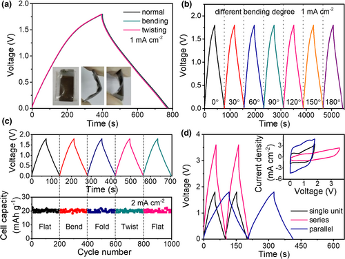
To manifest the potential of the FZHSC device for practical applications in portable and wearable electronics, the electrochemical performance was investigated by considering real conditions. Figure 3a displays the GCD curves of our FZHSC subjected to different shape deformations (insets are the optical images of the device at different states). As can be seen, the GCD curves upon bending or twisting almost overlap with the normal state. Moreover, the electrochemical performance changes little with the increase in the bending degree (up to 180 °C), as evidenced with the negligible variation in GCD profiles in Figure 3b. Even more noteworthy is that the FZHSC device can suffer successive bending, folding and twisting without affecting the GCD profiles and the specific capacitance (Figure 3c). All the above directly indicates good mechanical robustness and excellent flexibility of our FZHSC. In addition, our FZHSC can be readily connected in parallel or in series to change the output current or voltage to meet the energy and power supply for practical applications. As demonstrated in Figure 3d, combined FZHSC device assembled in a fashion of 2 in parallel or 2 in series delivers twice increase in discharge time (capacitance) or voltage in the GCD curves, respectively, the CV changes accordingly in line with physical law, as shown in the inset of Figure 3d. These results ambiguously highlight the great potential of integrating our FZHSC device into real electronics.
In some practical applications, flexible electrochemical energy storage devices need to work at cold and hot environments and endure extreme mechanical deformations. To this end, the design of multifunctional gel electrolyte is especially crucial. Herein, a unique anti-freezing and mechanically robust PVA hydrogel electrolyte (called HG-F) was further designed and used to construct an innovative FZHSC. As illustrated in Figure 4a, PVA was firstly well dispersed in a ZnCl2 solution with GL additive. After freezing at −18 °C and thawing at room temperature, the HG-F network with some PVA microcrystalline region as the crosslink point was assembled by hydrogen bonding between PVA, GL, and H2O. The as-prepared HG-F is homogeneous and transparent (Figure 4b,c), which is different from the hydrogel attained directly at room temperature (named HG-R; Figure S6). For HG-F, during the partial PVA crystallization under freezing, the movement state of PVA molecular chain was simultaneously frozen at −18 °C, which is crucial to keep the hydrogel transparent.[37, 38] Thanks to the presence of GL, the HG-F hydrogel was difficult to freeze at −50 °C, indicative of the satisfied anti-freezing nature (Figure 4d; the hydrogel without GL is entirely frozen at −50 °C). DSC measurement was carried out to analyze the freezing point and thermal stability of the HG-F hydrogel electrolyte. As displayed in Figure 4e, the HG-F gel electrolyte demonstrates an ultralow freezing point of −105.73 °C and a high thermal stability temperature of 84.57 °C. In general, polyhydric alcohol could suppress the water's freezing point effectively via breaking the hydrogen-bond network of water molecules, and chlorinated salts could also lower the freezing point of water.[39] Furthermore, by simultaneously using the freezing/thawing technique to synthesize hydrogel, the interconnected PVA molecular chains interact and tangle and form 3D crosslinked structure, which are closely bonded by Van der Waals and hydrogen bond; free H2O molecules are thus drastically decreased.[40] Consequently, the attained HG-F gel is stable within quite wide-temperature range.
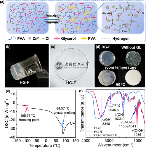
X-ray diffraction pattern in Figure S7 confirms the presence of some PVA microcrystalline in the gel with diffraction peaks located at 19.55° (101), 18.06° (100), and 21.87° (200). The Fourier transform infrared spectroscopy (FTIR) spectra of HG-F, HG-R, and HG-F without GL are comparatively given in Figure 4f. As can be seen from the curves of HG-F and HG-R, using the freezing/thawing technique has mainly changed the peak intensities of functional groups of PVA. In the enlarged FTIR spectra in Figure S8, the peaks at 1108 and 1041 cm−1 correspond to the symmetric stretching vibration and asymmetric stretching vibration of O-C-C, indicative of the crystalline and amorphous sequences in PVA.[40, 41] The crystalline/amorphous ratio of PVA in HG-F and HG-R is estimated to be ~1.12 and 1.08, respectively, indicating the increase in PVA crystallinity when using the freezing/thawing method and agreeing with the XRD result. The broad and strong absorption band from 3200 to 3500 cm−1 corresponds to the stretching of hydroxyl groups. Without adding GL, the HG-F electrolyte exhibits stronger absorption peak, implying the presence of large amount of free hydroxyl groups from H2O and PVA. In the presence of GL (electrolytes of HG-F and HG-R), the peak intensity decreases and the peak shifts to a lower wavenumber, which directly confirm the presence of a very large number of inter- and intramolecular hydrogen bond between GL and PVA molecule chains.[42]
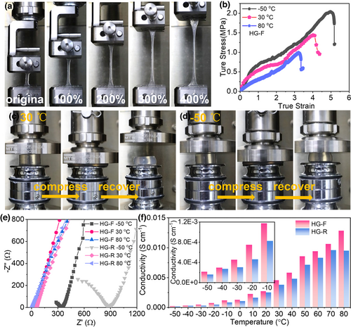
Besides, the as-prepared HG-F gel electrolyte exhibits good tensile strength and high stretchability of 400% strain (Figure 5a), characteristic of high elasticity. In contrast, the HG-R gel displays just 100% strain (Figure S9), and it broken when large straining was imposed. Figure S10 presents the tensile stress-strain curves of the HG-F and HG-R at 30 °C, the two hydrogel electrolytes demonstrate 1.43 and 0.48 MPa tensile strength, and 400% and 100% elongation at break, respectively. The tensile strength enhancement of HG-F is mainly due to the increased crystalline domains density in the 3D crosslinked PVA gel caused by intermolecular hydrogen bonding formed at low temperature, which makes crystal lattice contacted closer.[40] The tensile stress-strain profiles of the HG-F at different temperatures are given in Figure 5b. As can be seen, the HG-F always demonstrates good tensile property, despite that at higher temperature, the toughness is somewhat weakened due to softening. With the increase in temperature, the PVA matrix is easy to change the shape, but the intermolecular interaction in the gel electrolyte is disturbed, resulting in the reduction in the hydrogel strength and tensile modulus. Similarly, the compressive strengths of HG-F are better than HG-R (Figure S11), as further confirmed by the reversible extrusion experiment of HG-F at 30 and −50 °C in Figure 5c,d. We further calculated the ionic conductivities of the HG-F at different temperatures based on electrochemical impedance spectroscopy (EIS) results and compared with HG-R (Figure 5e).[27, 43] As expected, the ionic conductivity is increased as the temperature rises (Figure 5f and its inset). In addition, HG-F always shows higher conductivities than HG-R, which should be due to the unique PVA microcrystalline-involved 3D crosslinked electrolyte structure shaped during the freezing/thawing process (providing 3D ion transport channels). For HG-F, due to the ultralow freezing point, a high ionic conductivity of 0.21 mS cm−1 could still be sustained at ultralow temperature of −50 °C, which is acceptable for device operation.
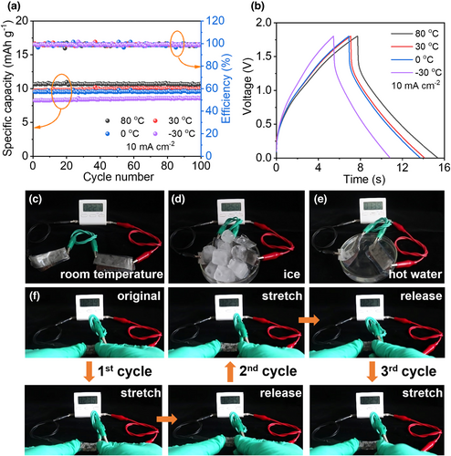
To demonstrate the design of the anti-freezing and stretchable Type II FZHSC, a sheet of the HG-F hydrogel electrolyte, serving as the separator at the same time, was sandwiched between the δ-MnO2 cathode and AC anode to assemble the device. It is quite encouraging that the fabricated FZHSC could be normally charged/discharged and well cycled at 10 mA cm−2 at temperatures of −30~80 °C; it retains almost 100% of the initial specific capacitance together with a high coulombic efficiency of ~100% at 80, 30, 0, and −30 °C. These results unambiguously prove its good anti-freezing property and thermal stability within wide operation temperature (Figure 6a,b). As empirical evidence for practical application, two anti-freezing FZHSCs were connected in series to power a commercial electronic timer at room temperature, ice water, and hot water. As displayed in Figure 6c–e, the connected devices all work well at different temperatures. We further designed the electrodes into a spring shape by alternatively cutting the two sides with similar interspacing, and fabricated stretchable FZHSCs. As illustrated in Figure 6f, two series-connected FZHSCs could continuously power the electronic timer when one of them is repetitively stretched by 200% for three times, indicative of excellent stretchability. The above-demonstrated multifunctionality of Type II FZHSC is apparently benefited from the synergy of our unique HG-F hydrogel electrolyte and highly flexible electrodes.
3 Conclusions
In summary, a novel aqueous FZHSC device is developed by using AC as anode, δ-MnO2 as cathode, and a multifunctional PVA-based hydrogel as electrolyte. In this device design, heavy Zn anode and its dendrite issue are avoided. Both electrode materials are prepared on flexible commercial current collector, together with multifunctional hydrogel electrolyte giving rise to a foundation for the assembly of innovative FZHSC. The resulting FZHSC exhibits good rate capability, high energy, and power densities and excellent cycle life as long as 30 000 times. The FZHSC can also work well under various successive bending, twisting, and folding conditions. Enabled by the anti-freezing and mechanically robust PVA hydrogel electrolyte designed by utilizing GL additive and freezing/thawing technique, the FZHSC exhibits robust stretchability and can be operated at −30~80 °C, ensuring all-climate application. The present work sets a good example of developing Type II ZHSCs into all-climate flexible energy storage devices for future wearable electronics.
4 Experimental Section
Synthesis of δ-MnO2 cathode
All chemical reagents were of analytical purity and used as received. The δ-MnO2 cathode was synthesized using a one-step electrodeposition method reported in our previous work.[9] Before electrodeposition, 0.01 M Mn(Ac)2 and 0.02 M NH4Ac were mixed as the electrodeposition solution. SS meshes as current collector was cleaned with ethanol using an ultrasonic cleaner for 15 min and then washed in distilled water several times, and dried. A typical three-electrode system on a CS 310 electrochemical workstation was used for electrodeposition. In detail, the SS was utilized as the working electrode, and a Pt plate and a SCE were used as the counter and reference electrodes, respectively. For growth, constant current polarization mode at 0.4 mA cm−2 was utilized for 1h. Finally, the as-prepared sample was cleaned in deionized water several times to remove the residual electrolyte and was then annealed at 400 °C for 30 min in a muffle furnace to improve interfacial adhesion.
Preparation of AC anode
The activated carbon (KYP-50, Kuraray) and TAB with a weight ratio of 1:1 were mixed and then rolled to a film on SS substrate and dried in a vacuum oven at 120 °C overnight.
Conventional gel electrolyte preparation and FZHSC assembly
To prepare the gel electrolyte, 4 g PVA 1799 (Aladdin Biochemical Technology, Shanghai, China) were added to 10 mL 2 M ZnSO4 and 0.1 M MnSO4 mixed solution and were stirred at 80 °C to completely dissolve the powders. The FZHSC device was assembled with the δ-MnO2 cathode, AC anode, and gel electrolyte. Prior to assembly, electrodes were first infiltrated with the sol electrolyte and left under ambient conditions to remove some redundant water. Then, they were placed face to face and left until the electrolyte was gelled (semisolid). Finally, the device was packed with parafilm for further testing. The total thickness of the device was ≈535 μm.
Multifunctional gel electrolyte preparation
The anti-freezing gel electrolyte was synthesized by dissolving 1.0 g polyvinyl alcohol (PVA, 1799) in 2 M ZnCl2 aqueous solution mixed with GL (1:1 w/w ratio) at 90 °C. After continuously stirring and entirely dissolving, the concentrated solution was cast into mold and cooled under −18 °C for 15 h (freezing). Finally, the temperature was returned back to room temperature (thawing) to get a transparent hydrogel electrolyte film.
Materials characterizations
The morphology and structures of the as-prepared electrode sample were characterized by SEM (Hitachi S-4800, Japan), HRTEM (JEM-2010FEF, 200 kV), XRD (Bruker D-8 Advance) with Cu Kα irradiation (λ = 1.54 Å). The surface chemical composition of δ-MnO2 was analyzed by XPS (Escalab 250-Xi, USA). The mass of the electrode materials was measured on an AX/MX/UMX Balance (METTLER TOLEDO, maximum = 9.9 g, d = 0.001 mg). Differential scanning calorimetry (DSC) measurement was acquired using the NETZSCH DSC 214 F3 Maia Instrument to measure the freezing point of the anti-freezing hydrogel electrolyte. FTIR was conducted using Nexus (500–4000 cm−1). The mechanical property testing of gel electrolytes was performed on Instron 5969.
Electrochemical measurements and calculations
All electrochemical measurements were performed on a CS 310 electrochemical workstation. To investigate the electrode properties, a three-electrode system was employed, whereas for device testing, a two-electrode mode was chosen. For electrochemical testing using liquid electrolyte, a mixed solution of 2 M ZnSO4 and 0.1 M MnSO4 was employed.
Acknowledgements
This work was supported by grants from the National Natural Science Foundation of China (Grant Nos. 52072136, 51972257, 51872104, and 52172229), the Ningxia Key R&D Program (2019BFG02018), and the Fundamental Research Funds for the Central Universities (WUT: 2021IVA115; 2021IVA071).
Conflict of Interest
The authors declare no competing financial interest.


