Affinity-Engineered Flexible Scaffold toward Energy-Dense, Highly Reversible Na Metal Batteries
Abstract
The practical deployment of metallic anodes in the energy-dense batteries is impeded by the thermodynamically unstable interphase in contact with the aprotic electrolyte, structural collapse of the substrates as well as their insufficient affinity toward the metallic deposits. Herein, the mechanical flexible, lightweight (1.2 mg cm−2) carbon nanofiber scaffold with the monodispersed, ultrafine Sn4P3 nanoparticles encapsulation (Sn4P3NPs@CNF) is proposed as the deposition substrate toward the high-areal-capacity sodium loadings up to 4 mAh cm−2. First-principles calculations manifest that the alloy intermediates, namely the Na15Sn4 and Na3P matrix, exhibit the intimate Na affinity as the “sodiophilic” sites. Meanwhile, the porous CNF regulates the heterogeneous alloying process and confines the deposit propagation along the nanofiber orientation. With the precise control of pairing mode with the NaVPO4F cathode (8.7 mg cm−2), the practical feasibility of the Sn4P3 NPs@CNF anode (1* Na excess) is demonstrated in 2 mAh single-layer pouch cell prototype, which achieves the 95.7% capacity retention for 150 cycles at various mechanical flexing states as well as balanced energy/power densities.
1 Introduction
The soaring demands for transportation electrification and renewable power system integration have motivated intensive explorations of the low-cost, energy-dense rechargeable power sources.[1-4] Na metal batteries (SMBs) are considered as an alternative energy storage format due to the natural abundance, high theoretical capacity (1166 mAh g−1), and the low equilibrium potential (−2.71 V vs standard hydrogen electrode) of Na.[5, 6] However, the practical deployment of the metallic anodes has been seriously restricted by its irreversible reactivity with the aprotic electrolytes and the fragile solid electrolyte interface (SEI) formation.[7-9] Moreover, the volume propagation of the Na deposits aggravates the uneven dendrite accumulation, inducing the separator penetration or internal short circuit scenarios.[10, 11] Upon the subsequent desodiation process, the loose packing of the deposits would detach from the substrate and readily generate the “dead” Na. All the above issues inevitably deplete the cation reservoir and lead to the cul-de-sac of the practical battery life.[12, 13]
To regulate the Na deposition behaviors, extensive investigations have been devoted to the structural/compositional innovation of the substrates. For instance, the nanoarchitectured Al host, Cu nanowires, Ni foam, and so forth have been proposed to afford the sufficient space for metallic deposits and dissipate the effective current density (J).[14-23] However, the massy metallic substrates would sacrifice the gravimetric capacity merits of the Na anodes at the penalty. Consequently, the lightweight, carbonaceous scaffolds with 3D electrical pathway and chemical stability (i.e., carbonized wood, carbon felt, and graphene film) were proposed as the alternative hosts due to the low-cost merits and additional possibility of the structural tailorability.[24-27] However, the carbon frameworks exhibit unsatisfactory affinity toward Na deposition due to the intrinsic lattice mismatch between body-centered cubic (bcc) Na and the sp2/sp3 carbon allotropes.[28, 29] In this sense, the well reconcile of the inactive mass/volume ratio, mechanical robustness as well as regulated deposits accommodation in the carbonaceous scaffold remains an unresolved issue in the practical SMB system, let alone the structural robustness at the high-areal-capacity loadings or under geometric flexing states.[30-32]
To regulate the metallic deposition behavior within the carbonaceous matrix, pioneer studies attempted to decorate the sodiophilic species on the substrates toward the enhanced Na affinity and mitigated nucleation barrier.[33-36] On the basis of the spatial arrangement of the sodiophilic sites, these hybrid substrates can be divided into several categories. One type involves the modification of sodiophilic species (i.e., specific functional groups, metal oxides, or metallic species with the infinite Na solubility) on the skeleton surface.[37-42] However, the direct exposure of the as-formed NaxM intermediates to the electrolytes may aggravate the parasitic solvent/salt reduction and irreversibly deplete the Na inventory. Another configuration is to encase the sodiophilic particles (i.e., Au, Sn, and CoN) within the carbonaceous framework.[43-47] Nevertheless, the aggressive volume expansion of the alloying process still suffers from the internal stress fluctuation, particle agglomeration, and even the electrode pulverization upon the repetitive cycling. Recently, Qian et al. investigated the crucial size effect of the sodiophilic species on the maximized affinity and the balanced mechanical stress distribution.[48] However, the particle size control and uniform distribution of the sodiophilic alloys always involve tedious fabrication procedures, for instance, the template-assisted methods or deliberate precursor treatments.[49-53] In this sense, the coherent Na affinity engineering and the spatial arrangement of the sodiophilic species in the carbon host, through a scalable strategy, is still at the heart of the rational anode design.
In this article, we constructed the mechanical flexible, lightweight (1.2 mg cm−2) carbon nanofiber (CNF) scaffold as the Na deposition substrate. This configuration design spatially confined the evenly distributed Sn4P3 nanoparticles (NPs) of ~2–5 nm within the mesopores to suppress the volume expansion of the alloying process and reduce their direct contact with the electrolyte. First-principles calculations based on density functional theory (DFT) elucidate that the alloying-induced heterogeneous intermediates (Na3P and Na15Sn4) serve as the sodiophilic sites to enhance the Na affinity. As a result, the Sn4P3 NPs@CNF electrode could maintain a reversible, high-capacity-loading (4 mAh cm−2 at 1 mA cm−2) with an average Coulombic efficiency (CE) of 99.6% and mitigated voltage hysteresis of 26 mV upon the symmetric plating/stripping cycling. As the presodiated Sn4P3 NPs@CNF electrode (1* Na excess) was paired with the NaVPO4F cathode (8.7 mg cm−2) in a single-layer pouch cell (2 mAh), the prototype exhibits a cycling endurance even upon the geometric flexing with the energy density of 261.8 W h kg−1 at the highest power output of 1047.2 W kg−1 (calculated based on the active materials). The affinity-engineered carbon scaffold with the nanoconfined, ultrafine sodiophilic species was thus expected to broaden the horizon of the flexible, energy-dense metallic battery constructions.
2 Results and Discussion
The fabrication procedure of Sn4P3 NPs@CNF is schematically illustrated in Figure 1a. Firstly, the Sn2+/PAN/PMMA composite film with preeminent mechanical flexibility was prepared by a scalable electrospinning process (Figure 1b). Upon the subsequent calcination process, the as-spun fabric exhibits the mesopores generated from the pyrolysis of PMMA (the morphology shown in Figure S1, Supporting Information). After the low-temperature phosphorization process at the completion, the CNF framework maintained the original interconnected nanofibers of ~650–700 nm in diameter (Figure 1c) with observable mesopores (Figure 1d and Figure S2, Supporting Information). As shown in Figure 1e, the high angle angular dark field-scanning transmission electron microscopy (HAADF-STEM) image and corresponding energy dispersive spectrometer (EDS) mappings confirm that the Sn and P elements are homogeneously dispersed within the carbon nanofibers. The high-resolution TEM (HRTEM) image of the enlarged region exhibits that the ultrafine nanocrytallines with the average particle size of 2–5 nm were encapsulated within the amorphous carbon, while the interplanar spacing of 0.285 nm corresponds to the (107) crystal plane of Sn4P3 (Figure 1f and Figure S3, Supporting Information). For comparison purpose, the Sn4P3@CNF was also prepared without the dose of pore-forming agent, that is, PMMA. The as-obtained product thus exhibits the serious agglomeration of the Sn4P3 particles (~150–200 nm in diameter) on the CNFs surface, implying the crucial nanoconfinement of the mesopores for the particle size control (Figure S4, Supporting Information). Correspondingly, the well-crystallized hexagonal Sn4P3 with space group of R-3m (PDF#73-1820) was confirmed in the X-ray diffraction (XRD) pattern (Figure S5, Supporting Information); in contrast, the diffraction peak intensity of the Sn4P3 NPs@CNF drastically weakened, which echoes with the observation of only the ultrafine crystallites encapsulated within the fibers. The weight content of the Sn4P3 species was measured and analyzed by thermal gravity analysis (TGA) upon the pyrolysis process and corresponding differential scanning calorimetry (DSC) curves. As depicted in Figure S6, Supporting Information, the initial mass decrease below 200℃ was attributed to the evaporation of water. Afterward, the resulted intermediates SnO2 was left while P2O5 was vaporized at 300, followed by the combustion of the carbon material. Specially, corresponding calculations based on Sn4P3 NPs@CNF indicated the mass loading of Sn4P3 as ~20.7 wt.%. Raman spectra demonstrate the relative high ID/IG ratios (the defect-induced peak intensity to sp2 hybridization graphitic peak intensity) for multihole CNF and CNF as 1.15 and 1.12, respectively, indicating amorphous carbon nature with numerous defects in the fibers (Figure S7, Supporting Information). Additionally, the coexistence of Sn, P, C, and N elements in the Sn4P3 NPs@CNF was validated by X-ray photoelectron spectroscopy (XPS). The core-level C 1s spectrum, as shown in Figure S8a, Supporting Information, demonstrates the sp2/sp3 C-C characteristic sub-peaks (284.4/284.8 eV), the C=N bond at 285.8 eV, N-C=O(N) bond at 288.1 eV, and the C=O peak (289.0 eV); correspondingly, the core-level N 1s spectrum exhibits the peaks at 397.8 eV, 399.3 eV, and 401.1 eV that assignable to pyrrolic N, pyridinic N, and quaternary N, respectively (Figure S8b, Supporting Information), suggesting the successful incorporation of the nitrogen dopants. As shown in Figure S8c, Supporting Information, the core-level Sn 3d spectrum could be deconvoluted into the subpeaks of Sn 3d5/2 (487.1 eV) and Sn 3d3/2 (495.2 eV) species. In addition, the P 2p spectrum possesses the 2p3/2 (130.4 eV) and 2p1/2 (131.5 eV) peaks, which can be attributed to the P-Sn bond in Sn4P3 as previous reports and further demonstrate the presence of Sn4P3 species; in addition, the P–O bond (136.2 eV) is ascribed to some inevitable oxidation species on the surface (Figure S8d, Supporting Information).[54, 55] Figure 1g exhibits the mechanical flexibility of the Sn4P3 NPs@CNF film with the current-potential response at the flat, bending, and relaxing states. The voltage is swept from 0 V to 1 V with the scan rate of 1 mV s−1, and the thickness of the film is 42 μm (Figure S9, Supporting Information). At different geometrical states, the negligible change in resistance manifests the excellent electrical continuity and structural stability of the integrated deposition substrate.
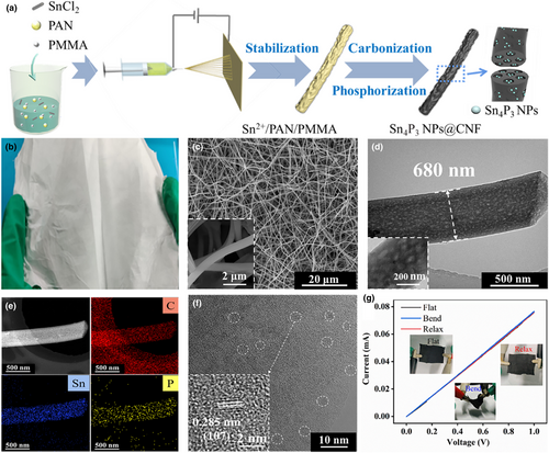
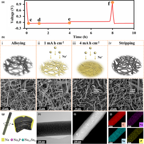
Figure 2a exhibits the galvanostatic discharge/charge voltage profile at 1 mA cm−2 and the morphologies evolution at different voltage stages is tracked by scanning electron microscope (SEM) images (Figure 2c–g). As elucidated in Figure 2b, the Na deposits gradually spread from the inner pore voids of the fibers to interspace among the fibers upon the piling-up of the loading capacity. Specifically, this trend was verified via ex-situ SEM images: After the heterogeneous alloying reaction, the 3D network architecture is still preserved with a slight variation on account of the thin SEI formation (Figure 2c). Then Na deposits gradually propagate along the one-dimensional orientation of CNFs at the capacity loadings of 1 mAh cm−2 (Figure 2d). Distinctly, the Na, Sn, and P elements are homogeneously distributed along the CNF after the plating process based on the TEM and elemental maps from Figure 2h–j, indicating the Na deposits were indeed confined within the interior voids and around the fibers (Figure 2g and Figure S10, Supporting Information). From EDS mapping, it can be taken notice of that with the amount of Na metal deposition increases, the fiber interior is filled and an obvious layer of Na emerges outside the CNF after plating for 2 mAh cm−2 at 1 mA cm−2 (Figure S11, Supporting Information). The uniform amorphous Na layer outside the CNF further proves that when the deposition amount is limited, Na metal will enter the CNF preferentially; with the deposition amount increases gradually, the metallic Na will be uniformly deposited along the one-dimensional CNF due to the regulatory effect of Na15Sn4 and Na3P. As the Na deposition amount accumulated to 4 mAh cm−2, the ensuing plated Na increasingly extended from the existing void positions to the gap space among the fibers without any discernable dendrites (Figure 2e). On the contrary, the mossy deposits emerged on the Sn4P3@CNF film (Figure S12, Supporting Information) and the dendritic Na protruded from the CNF substrate (Figure S13, Supporting Information) after plating 4 mA h cm−2. Upon the complete stripping at 1 mA cm−2 for 4h, the Sn4P3 NPs@CNF recovered to its original 3D interconnected nanofibers structure without remaining Na deposits (Figure 2f).
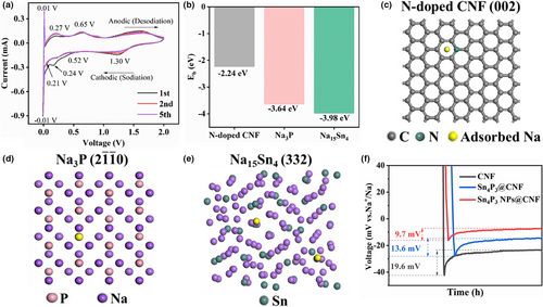
The pair sharp peaks at −12/13 mV correspond to the Na plating/stripping process. The almost overlapped CV curves from the second cycle onwards further demonstrated the cycling reversibility. To further explore how the Na15Sn4 and Na3P intermediates affect the Na affinity toward CNFs, DFT calculations and electrochemical evaluations are combined to compare the Na deposition process on various substrates. Figure 3c–e exhibit the optimized geometrical structures of a Na atom adsorbed on N-doped CNF (002), Na3P (2 0), and Na15Sn4 (332), respectively, while the DFT calculations were employed to estimate the adsorption energies (Figure 3b). The N-doped CNF (002) exhibits a limited binding energy (−2.24 eV), which shows much lower value than Na3P (−3.98 eV) and Na15Sn4 (−3.64 eV). In addition, Figure S14, Supporting Information shows that the computation of Na ions on the pure CNF (002, −2.14 eV) foil is rather weaker than nitrogen dopant species, such as graphitic N-doped CNF (−2.21 eV), pyrrolic N-doped CNF (−2.26 eV), and pyridinic N-doped (−2.30 eV). As a result, Na atoms preferentially rivet to the sodiophilic sites on the N-doped CNF. And the Na nucleation behavior was investigated at the current density of 1 mA cm−2 upon the initial deposition process (Figure 3f). The nucleation overpotentials of Sn4P3 NPs@CNF and Sn4P3@CNF anodes are 9.7 and 13.6 mV, which are much lower than that of the CNF anode (19.6 mV). The above results well echo with the deposition behaviors described in Figure 2, Figures S12 and S13, Supporting Information. In this sense, the ultrafine Sn4P3 NPs transform into the heterogeneous nucleation sites, namely the Na-Sn and Na-P intermediate alloys, with the enhanced levels of the Na affinity and mitigated nucleation barriers. Meanwhile, the nanoconfinement of the heterogeneous alloying and plating/stripping process within the mesopores renders the reversible Na storage behavior of the Sn4P3 NPs@CNF electrode.
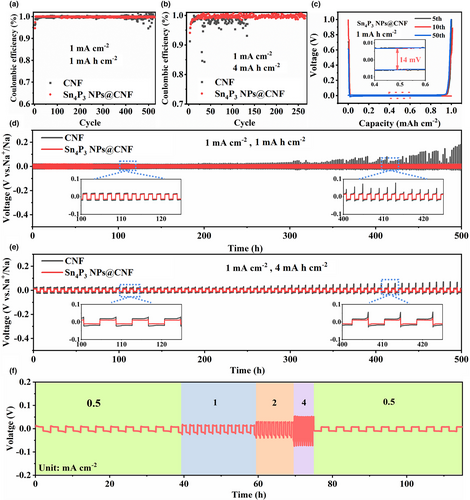
To evaluate the electrochemical stability of the Sn4P3 NPs@CNF compared to Sn4P3@CNF and CNF, the half cells were assembled by employing the Na foil as the reference and tested at different capacities. Before cycling, the coin cells were firstly activated over three cycles between 0.01 and 1.0 V (details in the experiment section). At the current density of 1 mA cm−2 with a capacity of 1 mAh cm−2, the Sn4P3 NPs@CNF symmetric cell maintained a stabilized plating/stripping process for over 500 cycles with an impressive average CE of 99.8% (Figure 4a). On the contrary, the CNF substrate experienced the voltage fluctuation after 350 cycles. As the deposition amount piled up to 4 mAh cm−2, the Sn4P3 NPs@CNF still retained the high average CE of 99.6% for 250 cycles, while the CNF counterpart exhibited the obvious CE decline only after 50 cycles and induced the short circuit after 130 cycles (Figure 4b). Meanwhile, from the enlarged view of the voltage-capacity curves of Sn4P3 NPs@CNF (1 mA cm−2 with the capacity of 1 mAh cm−2), the voltage polarization stabilized at 14 mV without noticeable variation (Figure 4c). To further explore the galvanostatic cycling stability, Figure 4d,e demonstrate the voltage change of symmetric cells by depositing Na onto the Sn4P3 NPs@CNF and CNF substrates at 1 mA cm−2. The Sn4P3 NPs@CNF anodes exhibited rather stable plating/stripping voltage curves as the deposition amount was controlled as 1 mAh cm−2 or 4 mAh cm−2, in sharp contrast to the vigorous voltage fluctuation of the CNF symmetric cells. The insets in Figure 4d,e reveal the enlarged curves from 100-125 h and 400–425 h, further demonstrating the smooth and more stabilized voltage hysteresis values (22 mV for 1 mA h cm−2, 26 mV for 4 mA h cm−2) of Sn4P3 NPs@CNF symmetric cells. Cycling performances of Sn4P3@CNF symmetric cell were also evaluated at the similar galvanostatic conditions, which delivered an inferior cycling stability with the increased voltage hysteresis, and finally the short circuits after 350 h at the deposition amount of 1 mA h cm−2 or 450 h at 4 mA h cm−2 (Figure S15, Supporting Information). The rate capability of the Sn4P3 NPs@CNF was also evaluated at 0.5, 1, 2, and 4 mA cm−2 (Figure 4f), and the result showed the ultra-stable plating/stripping process even at the high-power output. As the current density returned to the original value of 0.5 mA cm−2, the voltage hysteresis also recovered to the similar value of 15 mV as the initial cycles, indicating the reversibility of the stripping/plating process. Furthermore, the electrochemical impedance spectroscopy (EIS) of the Sn4P3 NPs@CNF and CNF cells before and after cycling was measured to compare the charge-transfer resistance (Rct) values (Figure S16, Supporting Information and Table S2, Supporting Information). Before cycling, the Sn4P3 NPs @CNF electrode delivers a much lower Rct (~15.1 Ω), which is only about half the value of the CNF electrode (~26 Ω), suggesting the intensive electrochemical kinetics of Sn4P3 NPs@CNF. Both the Sn4P3 NPs@CNF and CNF cells show dramatically decreased Rct after 50th cycle under a current density of 1 mA cm−2. However, the Rct of Sn4P3 NPs@CNF reduced to a much lower value (6.2 Ω) than that of CNF electrode (11.7 Ω). The reduced interfacial Rct of Sn4P3 NPs@CNF demonstrates that a stable SEI film generates during the activation process and the contact of electrolyte/electrode interface improves. In this regard, the improved cycling stability of the Sn4P3 NPs@CNF demonstrated the crucial coupling of the coherent sodiophilic sites and their spatial arrangement in the substrate design.
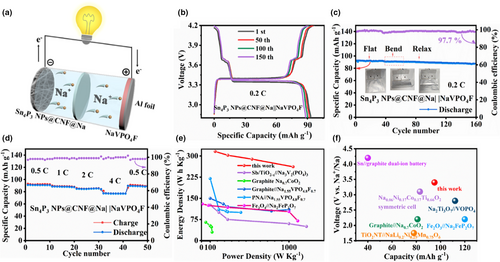
In order to further verify the feasibility of Sn4P3 NPs@CNF anode in a practical battery system, the 2 mAh single-layer pouch cell was constructed with NaVPO4F as cathode (8.7 mg cm−2) and NaPF6 solution (1 M) in diglyme as electrolyte (40 μL mAh−1), as schematically illustrated in Figure 5a. The Sn4P3 NPs@CNF could serve as the free-standing anode for cell assembly after simple treatment: initially, 2 mAh capacity of Na metal (1* Na excess) was pre-deposited (Sn4P3 NPs@CNF@Na) upon the activation procedures (details are described in experimental section). As shown in Figure 5b, the voltage profiles of Sn4P3 NPs@CNF@Na||NaVPO4F full cell maintain a superimposable charge/discharge plateau and stabilized discharge capacity at the 1st, 50th, 100th, and 150th cycles. Figure 5c evaluates the cycling stability of the Sn4P3 NPs@CNF@Na||NaVPO4F full cell under different bending conditions. Remarkably, Sn4P3 NPs@CNF@Na||NaVPO4F delivered an average CE value of 99.3% with the capacity of 91.4 mAh g−1 at the initial flat state. Afterward, the full cell was bended during the 40th cycle to 60th cycle and retained 97.3% (89.5 mAh g−1) of the original capacity. Finally, after returning to the flat state at the 61st cycle, a reversible capacity of 88.1 mAh g−1 and 95.7% capacity retention for 150 cycles could be obtained. In addition, the Sn4P3 NPs@CNF@Na||NaVPO4F full cell exhibited charge capacities of 93.1, 88.4, 84.9, and 77.2 mAh g−1 at the rates of 0.5, 1, 2, and 4 C, respectively. Subsequently, the discharge capacity recovered to 91.6 mAh g−1 as the cycling rate returned to 0.5 C (Figure 5d). Based on the approximate calculations with the consideration of the electrodes in the full cell model, the Sn4P3 NPs@CNF@Na||NaVPO4F model realized a specific energy of 261.8 W h kg−1 at the high-power output of 1047.2 W kg−1, which surpassed the previously reported values (Table S1, Supporting Information, Figure 5e).[56-60] Furthermore, the improved balance between voltage and capacity further validates the rational design of the lightweight Sn4P3 NPs@CNF substrate, which simultaneously maintains the cycling endurance, mechanical flexibility, as well as power/energy densities in the as-constructed SMB prototype (Figure 5f).[59, 61-64]
3 Conclusion
In summary, we regulate the high-capacity-loading Na deposition by spatially confining the sodiophilic Sn4P3 NPs within the mesopores of the flexible, lightweight CNF scaffold. Based on the DFT calculations, the heterogeneous alloy intermediates (Na15Sn4 and Na3P) effectively enhance the Na affinity to mitigate the overpotentials upon plating/stripping cycles. As a result, the Sn4P3 NPs@CNF scaffold endows the cycling endurance with high CE of 99.6%, robust cyclability for 500 h, and low hysteresis of ~ 26 mV at 4 mAh cm−2. Furthermore, the as-constructed pouch cell model (2 mAh) that paired with the NaVPO4F cathode displays the balanced energy/power densities with satisfactory cyclability even upon the geometric deformation. The configuration design of this flexible SMB model could thus highlight the pivotal spatial arrangement and particle size control of the sodiophilic species toward the dendrite regulation, thereby promoting the energy/power-dense SMB construction.
4 Experimental Section
Chemical reagents and materials
Dihydrate tin chloride (SnCl2·2H2O, 98%), sodium hypophosphite (NaH2PO2, 99.0%), N, N-dimethylformamide (DMF, anhydrous, 99.8%, Aldrich), polyacrylonitrile (PAN, average Mw = 150000, Aldrich), and poly (methyl methacrylate) (PMMA, average Mw = 15000, Aldrich) were obtained from Sinopharm Chemical Reagent Co., Ltd. (Shanghai, China). All the chemicals used in this experiment were analytical grade and used without further purification.
Synthesis of Sn4P3 NPs@CNF, Sn4P3@CNF, and CNF
The Sn4P3 NPs@CNF was prepared through an electrospinning technique followed by thermal treatment. First, 0.72 g PAN was dissolved into 7 mL DMF solvent, while 1 g SnCl2·2H2O and 0.08g PMMA were put into 3 mL DMF by magnetic stirring at 60℃ for 6 h to form the transparent solutions. Then, PAN and PMMA solutions were mixed and stirred overnight at 60℃ to generate the precursor solution. The electrospinning fluid was then loaded into 10 mL plastic syringe, and the needle tip of the syringe was connected to the high positive voltage of the power supply. The distance between the drum collector and the needle tip was set to be 15 cm with a voltage of 18 kV. The flow rate of the mixed polymer solution was kept at 0.05 mm min−1. The non-woven fabric after electrospinning process was dried in the air at 280℃, followed by the calcination at 650°C and phosphorization treatment with NaH2PO2 at 280℃ for 2 h, respectively. The as-obtained sample was designated as Sn4P3 NPs@CNF. For comparison, the precursor solution without PMMA dose was prepared and designated as Sn4P3@CNF, as well as the CNF network was also prepared by only adding the PAN as the precursor while keeping other parameters identical.
Synthesis of sodium vanadium fluorophosphate (NaVPO4F)
A two-step carbon thermal reduction was conducted to prepare the NaVPO4F cathode material. Firstly, V2O5, C6H12O6, and NH4H2PO4 were mixed uniformly with the molar ratio of 6:3:1 to form the VPO4 precursor. After that, the VPO4 precursor was calcined for 8 h under N2 at 750 ℃. For the second step, the VPO4 precursor, NaF, and C6H12O6 were ground together with the molar ratio of 2:2:1. Finally, the mixtures were calcined at 750℃ under N2 for 4 h to get the phase-pure NaVPO4F cathode.
Materials Characterization
X-ray diffraction (XRD, STOE, Cu Kα, λ = 1.5418 Å) was used to test the crystal structure of the synthesized nanofibers. The 2θ angular region ranged from 20° to 60° at a scan rate of 5° min−1. The X-ray photoelectron spectroscopy (XPS, Kratos Axis Supra) was conducted to analyze the chemical states of sample elements. The morphology of samples was characterized by operating field-emission scanning electron microscopy (FESEM, FEI NovaSEM 450) at 15 kV, transmission electron microscope (TEM), and high-resolution TEM (HRTEM, JEM-2010 microscope) with energy-dispersive X-ray spectroscopy (EDS) at 200 kV. Brunauer-Emmett-Teller (BET, micromeritics ASAP 2460 system) analysis was proceeded via nitrogen adsorption and desorption isotherms. Raman analysis was performed on a HORIBA Raman spectrometer by using a 532 nm laser source. Thermal gravity analysis (TGA, METTLER Toledo TGA-DSC 3+) was carried out in the air from 35°C to 800°C with a ramping rate of 10°C min−1. The Gaussian-Lorentzian shape GL (30) functions were used to fit the peak line shapes.
First-Principles Calculations
Density functional theory (DFT) calculations were conducted by using the Cambridge Sequential Total Energy Package (CASTEP).[65, 66] The generalized gradient approximate value by Perdew and Wang with Vanderbilt-type ultra-soft pseudopotentials was used to treat the exchange correlation function.[67, 68] The plane wave cut-off energy was 370 eV. All the atoms in the structures were relaxed until the residual forces were less than 0.01 Å−1 and the convergence tolerance quality was less than 1.0 × 10⁻⁵ eV. The 1 × 1 × 1 k points were used for sampling in the Brillouin zone. Each model was made for interacting a Na ion into materials and the binding energy was defined as following: Eb = Etotal-Em-ENa, respectively, where Etotal, Em, and ENa were the total energy of CNF/Na15Sn4/Na3P model with a Na atom, the CNF/Na15Sn4/Na3P model, and a single Na atom.
Electrochemical Measurements
The 2032 coin cell was assembled in a glove box filled with argon, and then tested for Na storage performance. The calcined composite films were punched into discs (Φ = 12 mm) as the working electrodes. A metallic Na disc and a glass microfiber filter were used as the counter electrode and separator respectively. 20 μL NaPF6 solution (1 M) in diglyme was employed as the electrolyte. For the electrochemical testing of symmetric cells, the Sn4P3 NPs@CNF, Sn4P3@CNF, and CNF electrodes were tested after the activation process: the symmetric cells were initiated with three cycles between 0.01 and 1.0 V, using a current density of 0.5 mA cm−2 to remove the surface impurities. Then the electrodes were charged and discharged repeatedly at different capacities (1 mAh cm−2 and 4 mA h cm−2). For the cyclic voltammetry (CV) experiment, the test was conducted on a Solartron electrochemical workstation at a scan rate of 0.1 mV s−1 within a potential window of −0.1~2 V. For the full cell tests, a single-layer full cell (2 mAh) was assembled with the aluminum-plastic pouch. For the cathode preparation, as-prepared NaVPO4F material, Super P, and polyvinylidene fluoride (PVDF) (mass ratio = 8:1:1) were mixed in N-methyl pyrrolidone (NMP) and spread on the Al foil. The areal mass loading of the NaVPO4F electrode was controlled as 8.7 mg cm−2. The same electrolyte of the NaPF6 solution (1 M) in diglyme was used during the full cell assembly (30 μL mAh−1). The pre-deposited Sn4P3 NPs@CNF (1* Na excess) was used as anode after the activation process. In the galvanostatic charge/discharge test, the full cells were performed at 0.2 C (1 C = 115 mA g−1) at room temperature under the voltage window for 2.8-4.2 V. All the electrochemical tests were conducted with the Neware instrument.
Acknowledgements
Y.L. and M.B. contributed equally to this work. We acknowledge this work is financially supported by the National Natural Science Foundation of China (5217130394), the Natural Science Foundation of Shaanxi (2019KJXX-099, 2020YZ0037, 2019JLZ-09 and 2019QYPY-194), the Fundamental Research Funds for the Central Universities (3102019JC005), Key R&D Program of Shaanxi (No. 2019ZDLGY04-05), and the Development and Industrialization Fund (2020KJRC0120). Furthermore, we would like to thank the Analytical & Testing Center of Northwestern Polytechnical University for providing several testing instruments and the support of Swiss Platform for Advanced Scientific Computing PASC.
Conflict of Interest
The authors declare no competing financial interest.


