Scalable and Heavy Foam Functionalization by Electrode-Inspired Sticky Jammed Fluids for Efficient Indoor Air-Quality Management
Abstract
Functionalization of polymer foams by surface coating is of great interest for advanced flow-interactive materials working with well-controlled 3D open channels. However, realizing heavy functional coating via a fast and recyclable way remains a big challenge. Here, inspired by the battery electrodes, we propose a scalable mechanic-assisted heavy coating strategy based on the design of sticky jammed fluid (SJF) to conquer the above challenge. Similar to the electrode slurry, the SJF is dominated by a high concentration of active material (≥20 wt% of active carbon, for instance) uniformly dispersed in a protein binder solution. Due to the sticky and solid-rich nature of the SJF, one can realize a high coating efficiency of 60 wt% gain per coating. The critical factors controlling the coating processing and quality are further identified and discussed. Furthermore, the functionalized foam is demonstrated as a high-performance shape-customizable toxic gas remover, which can absorb formaldehyde very efficiently at different circumstances, including static adsorption, flow-based filtration, and source interception. Finally, the foam skeleton and the active materials are easily recycled by a facile solvent treatment. This study may inspire new scalable way for fast, heavy, and customizable functionalization of polymeric foams.
1 Introduction
Polymeric foams are very important structural materials with unique characteristics including high porosity, uniform and controllable pore structures, adjustable mechanical properties, etc. Therefore, polymeric foams have been widely used in insulation,[1-6] buffering,[7] packaging, and so on.[8-10] In spite of this fact, the high-value applications of polymeric foams are usually limited by available material functions if no modification has been applied. To address this need, foam functionalization has been a focus of the research on polymeric foams. Basically, there are three kinds of methodology to functionalize the polymeric foams. The first one is in-built method by foaming with functional additives, such as polymer foaming with functional nanofillers inside the melt[11-13] or with functional agent inside the foaming agents,[14] or obtain porous structure by etching the other phase.[15] This methodology is well-known in polymer foam processing and easy to scale up. The second methodology is the carbonization of polymeric foams into conductive or absorptive materials. For example, Haibo Li et al. fabricated a nitrogen/oxygen co-doped carbon foam by carbonizing commercial melamine foam at 800 °C in the presence of ZnCl2, which was employed as a monolithic electrode for supercapacitors.[16] Shuiliang Chen et al. prepared elastic carbon foam by direct carbonization of melamine foam and realized flexible electrodes for removal of waste organic chemicals and oil pollution from water surfaces.[17] The third and also the most flexible methodology is surface coating by various techniques, including dip-coating,[18-21] in situ modification by chemical reaction,[22-25] spraying coating,[26] electroplating,[27, 28] etc. For all the strategies above, they all have their advantages and disadvantages. Specifically, for the first one, it takes the full advantages of polymer processing, but the foaming processing itself has very strictly requirements on the processing properties of functional fillers, which may limit the choice of functional fillers. For the second one, it is very simple and effective, but the function is usually limited and realized by sacrificing the good mechanical properties of the foam. The last one is very popular due to its excellent design flexibility in composition and function of the coating layer, and also it is scalable. For all the reported strategies, it is usually challenging to achieve high loading of active materials per coating. In other words, realizing heavy coating of active materials via cost-effective and scalable way remains a big challenge for foam functionalization.
From application point of view, heavy coating of functional materials onto polymeric foams is a very cost-effective and flexible strategy for the fabrication of porous functional materials with various significant applications. Taking the indoor air pollution, for example, the interest in efficient air-quality management is gradually growing with the increasing concern about the possible influence on human healthy. Especially, for new house or house with new furniture, the indoor air quality is quickly polluted with volatile organic compounds (VOCs), such as formaldehyde and so on.[29-34] The concentration of toxic VOCs can easily reach the hazardous level due to limited ventilation.[35] Recent studies show that prolonged exposure to indoor toxic gases can lead to many chronic respiratory and neurological diseases.[36] Many cases have shown that indoor benzene has an adverse effect on the development of embryos and fetuses.[37] Currently, there are also some solutions to address the indoor gas pollution issues. For example, one can pretreat the furniture by physical coating to inhibit the releasing of toxic gases during use.[38] Another well-known and popular strategy is the use of activated carbon (AC) to remove toxic gases. AC is a well-known adsorption material due to its high specific surface area and good affinity to organic gases.[39, 40] Conventionally, most of the commercial products take the AC in the shape of small balls or big particles, which are either directly sealed in porous bags or coated onto porous substrates. For this conventional design of AC, the main advantages are the low cost and recyclability. However, some issues remain. Firstly, the specific absorption efficiency is very low due to the big size of AC, which limits the surface area for absorption. At the same time, a heavy coating with AC particles will easily generate close-packed structures that greatly increase the air-flow resistance. As a result, in order to remarkably improve the adsorption efficiency with a low air-flow resistance, heavy coating of micro-/nano-AC onto rationally designed porous substrates becomes an effective solution.
Here, in order to address the above needs, we propose a new strategy based on the design of sticky jammed fluid (SJF) and a scalable mechanic-assisted coating method. Specifically, as illustrated in Figure 1a, the design of SJF was inspired from the characteristics of electrode slurry. It is defined as a type of fluids filled with highly concentrated but well-dispersed nanoparticles or microparticles, which also shows sticky properties at the surface. It is well-known that electrode slurry is typically composed of active materials (AMs) or electrode particles and conductive nanoparticles, which are well-dispersed in a polymer binder solution. To achieve the desired electrochemical functions and device performance, the compositions of electrode slurry are well-designed to build thick functional porous electrodes as illustrated in Figure 1a. Usually, the solid concentration of the electrode slurry is much higher than conventional dispersions and it is typically in the range from 20 to 30 wt%, in order to achieve a high coating or electrode fabrication efficiency. At the same time, to ensure the formation of porous structures, the ratios among the components have been also well-optimized. For example, the AM weight fraction in the final dry composite electrodes is typically above 80 wt%. This is important as a high AM loading is beneficial to not only the porous structures, but also the capacity of the final electrodes.

The composition design of electrode slurry and the resultant microstructures of the electrode are very instructive realizing heavy functional coating of polymeric foams as illustrated in Figure 1b. Firstly, a type of sticky jammed fluid (SJF) with similar compositions to the electrode slurry is designed. This SJF is a special slurry with a high loading of active material (above 30 wt% of active carbon, AC) that is well-dispersed in adhesive protein binder solution (zein protein in mixture solvent of DI water and ethanol). The protein adhesive can form strong interfacial interactions with the foam skeleton at both wet and solid states. Secondly, due to the strong microscopic adhesion (micro-adhesion), the SJF can be easily coated onto the porous substrate but with the help of mechanic-assisted processing, such as roll-to-roll calendaring as illustrated by Figure 1b. This technology is therefore called as mechanic-assisted micro-adhesion guided (MAG) coating technology. This mechanic-assisted MAG coating technology is especially designed for the SJF, which is very viscous due to a high solid concentration. As a result, the foam can be evenly coated with a thick porous layer with electrode-like functional porous structures.
2 Result and Discussion
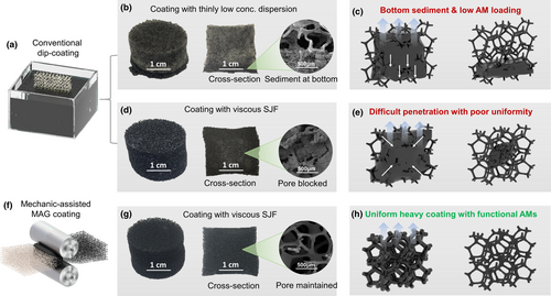
The coating quality of samples made through conventional dip-coating and the mechanic-assisted MAG coating was investigated first. As shown and illustrated in Figure 2a–c, conventional dip-coating of polyurethane (PU) foam with thin and low concentration AM dispersion generates obvious bottom sediment after drying (see Figure 2b,c). This phenomenon may be caused by a gravity-driven flow due to the low viscosity of the AM dispersion (see Figure S1a). Meanwhile, the photograph of the cross-section of the sample as shown by Figure 2b further uncovers the coating non-uniformity, in addition to a very limited AM gain per coating (see Figure S1b). For the sample dip-coated with the SJF, the AM loading per coating was notably improved (see Figure S2a). However, it faces two difficult problems. The first one is the non-uniform coating of AM inside the foam as shown by Figure 2d (also see the SEM images by Figure S2b,c). Secondly, it becomes more difficult or more time-consuming for the diffusion of SJF into the foam if the pore size becomes smaller (see Figure S2b,c). The first one may be caused by a difference in the evaporation rate between the surface and the inside during the drying process as illustrated by Figure 2e. The above two problems together finally lead to low coating quality and efficiency. Therefore, we propose a mechanic-assisted MAG coating strategy to address the above issues for dip-coating with the SJF. As shown by Figure 2f, a scalable roll-to-roll method is employed to help the diffusion of SJF into the foam. At the same time, the expansion of the foam after the compression is very helpful to open the pore channels during the drying. Via this new coating strategy with sticky jammed fluids, heavy and uniform AM coating can be realized in a highly efficient way, as shown by Figure 2g,h. Based on the authors’ knowledge, this is the first time to realize heavy porous coating onto polymer skeleton for foam functionalization.
The above uniform AM coating indicates strong interfacial interactions between the SJF and the PU foam, which plays a critical role in controlling the MAG coating process. Therefore, it is necessary to study how the compositions of the SJF contribute to the coating quality. Since the binder polymer must be the key for achieving good coating quality, the first task is to investigate the binder solution properties and their links to the interfacial interactions with the PU substrate. In this study, a biopolymer, zein protein, is chosen as a high-performance binder due to its well-proved dispersion capability for carbon materials,[41, 42] as well as the peptide bond that is similar to the backbone bond along the PU chain. Interestingly, it was found that the dissolution of zein protein is highly dependent on the solvent composition, specifically, the volume or weight ratio between ethanol and DI water. It is believed that the dissolution of protein is a process of breaking inter-chain and intra-chain interactions, including disulfide, hydrogen, van der Waals forces, and ionic and hydrophobic interactions.[43] Previous studies show that zein can be dissolved in the ethanol/DI water mixture solvent with ethanol volume fraction from 60 vol% to 95 vol%.[44] This conclusion is confirmed by our results as shown by Figure 3a–c. One can find that the solubility of zein in ethanol/DI mixture solvent increases obviously when the volume ratio increases from 6:1 to 9:1, as clearly demonstrated by the digital photographs and laser scattering testing with wavelength of 650 nm. Specifically, the system becomes more and more clear with the increasing of ethanol fraction (also see Figures S3). It indicates that a high ethanol/water molecule ratio is helpful to destroy the inter-chain interactions (see the cartoon in Figure 3a–c), and so the zein aggregation structures. This phenomenon only happens when the volume fraction of ethanol in the mixture is lower than 90 vol%.[45] This means the ethanol molecules have to work together with water molecules to completely dissolve the zein protein. Since zein has been wildly used as film-forming agent caused by its unique film formation property,[46-48] it is possible to perform peeling-off test for zein film coated onto the PU plate, which can reveal the interfacial interactions between the zein binder and PU skeleton. In this study, the influence of solvent composition on the binding strength of the zein binder onto PU substrate was particularly investigated. As illustrated in Figure 3d, the PU plate was fixed onto a stiff metal plate to avoid deformation during the peeling-off testing. Meanwhile, the peeling angle was maintained at 180°. The peeling strength was calculated based on the axial force. The peeling strength of all those three samples was compared in Figure 3e. One can find that the peeling strength increases notably with the increasing ethanol fraction in the zein solution. The averages are 4.2, 8.0, and 14.9 N m−1 for the samples with ethanol/DI water volume ratio of 3: 1, 6: 1, and 9: 1, respectively. This result indicates that opening the zein chain is beneficial to build strong interfacial interactions between the zein binder and the PU foam substrate.
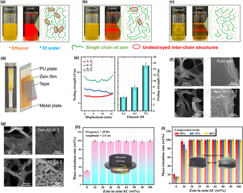
After optimizing the ethanol/DI water ratio for achieving strong binding performance, the effects of the weight ratio between zein binder and active carbon (AC) on the coating morphology and stability were further investigated based on the optimized solvent composition. On the basis of the SEM images by Figure 3f,g, one can find that the sample with pure zein solution shows uniform coating layer on the surface of PU skeleton. For the samples with high zein/AC ratio (8:2 to 5:5), the AC powder is almost completely covered by the zein binder, which forms a tight coating layer onto the AC particles. However, when the AC dominates the composite (zein/AC ratio lower than 3:7), the coating layer becomes porous (see Figures S4 for more images), which is very similar to the electrode microstructures well-known in batteries. It is believed that the porous structures of the coating layer will be in favor of absorption function, especially when a heavy AC coating is desired for achieving higher capture capacity. Whereas, if the mass fraction of zein in the zein/AC composite is too low, it might do harm to the stability of the coating layer. Therefore, the binding stability of the coating layer was further tested to figure out the critical value for the zein/AC ratio. Samples were firstly treated by vibration machine with a frequency of 20 Hz and amplitude of 2.5 cm for 5 min. The total mass of the samples before and after the vibration testing was recorded to calculate the mass-retention rate. The test result is shown in Figure 3h. As one can see from this Figure, the sample without zein binder is not stable and lost about 70 wt% of the coating. In contrast, for the sample with 10 wt% of zein in the zein/AC, the mass-retention rate increased to 99.63 wt%. With the increasing zein/AC weight ratio, the mass-retention rate maintains at a high level above 97 wt%. As a binder, zein plays an important role in controlling the coating stability even under compression of the foam. Therefore, destructive compression test was further employed to study the binding stability of samples as shown in Figure 3i. Again, the sample without zein binder exhibits a poor coating ability under compression. The mass-retention rate is 20.59 wt%, 14.62 wt%, and 14.61 wt% at compression strain of 50%, 75%, and 85% respectively. For the sample with 10 wt% zein in the zein/AC, the mass-retention rate is 96.72 wt%, 89.42 wt%, and 75.56 wt% at compression strain of 50%, 75%, and 85% respectively. This result indicates that the fraction of zein in the zein/AC coating layer should be further optimized to achieve good coating stability at both vibration and compression treatment. Interestingly, when the zein fraction is above 20 wt% in the zein/AC composite, the mass-retention rate becomes stable and remains a high level above 97.5 wt%. Based on the above stability and morphology studies, the zein/AC ratio was finally determined to be 2:8, which will be employed for the following studies.
Rheological test was done to study the rheological behavior of the slurry with different solid concentrations. As illustrated in Figure 4a, in low-frequency region (<1 Hz), the complex viscosity of the slurry increases notably with the increasing solid concentration. At the same time, shear thickening behavior was observed for the SJF samples, which can be viewed as the transition of dispersed phase into jammed phase at high shear rates. In order to determine the optimal solid concentration for the heavy coating, the rheological properties of SJFs during evaporation (simply referred as drying rheological testing below) were further investigated. Based on this testing, one can determine the solidification time of the SJF, which is critical for the coating processing. Figure 4b shows the setup for the drying rheological testing. As illustrated by the cross-section view, the SJF sample is filled into a specially designed sample holder, which exposes the SJF surface for evaporation. The solidification of the SJF will create an increasing torque for dynamic deformation, which is reflected by the apparent complex viscosity as shown by Figure 4c. From the drying rheological testing, one can find that the apparent complex viscosity is stable in a certain time zone, then sharply increases with evaporation time, and finally slowly increases with evaporation time. Based on this picture, we define the time of the stable zone as the processing time of that SJF. From the above testing, one can find that the higher the solid concentration of SJF, the faster the solidification. This result means that the solid concentration of the SJF cannot be too high if processing time is considered. However, from the coating efficiency point of view, a high solid concentration is desired for the heavy coating. As a result, there is an optimal processing window for the SJF coating as shown by Figure 4d. To find this window, the solidification time and the AM gain per coating are plotted in the same figure with the changing of solid concentration. When the solid concentration of SJF is too high, the AM gain per coating is high; however, its solidification time is too short to perform uniform heavy coating. When the solid concentration of SJF is too low, the AM gain per coating is very limited. Thus, the appropriate solid concentration is finally determined to be in the range of 25 wt% to 30 wt%. For simplicity, 30 wt% was selected for the following studies.
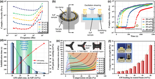
The mechanical properties of functional PU foam with different amount of AM loading were characterized by compression testing as illustrated in Figure 4e. The whole compression process can be divided into three sections. For section I, the skeleton with zein/AC coating layer is in its elastic region until the compress stress reaches the yield strength. In this region, the compression stress almost linearly increases with the increase in compression strain. For section II, the skeleton yields and the coating layer is broken. Therefore, this section can be viewed as yield region. During this region, the foam is notably compressed due to the shrinking of the pore volume. At some point, the compression reaches the section III, called as jammed region. In this region, the coated skeleton was compressed into a jammed state, where the skeleton is compressed tightly without little free space left (see the insert cartoon in Figure 4e). Here, the yield point is defined as the compression strength of the foam. Compared with the pure PU foam, coated foams possess much higher compression strength as shown by Figure 4f and Figure S5. One can find that the compression strength increases dramatically with the increasing of AM loading. It indicates that the AM layer act as mechanical reinforcement, in addition to function coating.
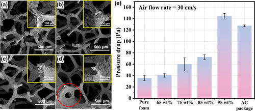
The SEM images of the samples with different AM loadings are shown in Figure 5a–d. One can find that when the AM loading is below 65 wt%, the coating layer cannot cover the entire skeleton (Figure 5a and Figure S6a). Uniform and completed coating is observed when the AM loading is around 75 wt% (Figure 5b and Figure S6c). The coating layer becomes thicker as the AM loading further increases to 85 wt% (Figure 5c and Figure S7b). However, some of the pores are blocked when the AM loading further increases to 95 wt% (Figure 5d and Figure S8). The extra AM blocking the pore structure is harmful to the air-flow efficiency. As shown in Figure 5e, the air-flow resistance of samples with different AM loading was investigated to study the air permeability at 30 cm s−1 air-flow rate. The pressure drop of pure foam is about 35.67 Pa and it increases slightly with the growing AM loading when it is lower than 90 wt%. The pressure drop is about 40.33 and 59.69 Pa when the AM loading is 65 wt% and 75 wt%, respectively. A further enhancement of coating thickness did not cause significant increase in pressure drop. The pressure drop is only about 72.33 Pa when the AM loading is as high as 85 wt%. However, the pressure drop rapidly climbed to 144 Pa when the AM loading is 95 wt% as lots of pores are blocked by the extra AM. For comparison, the same amount of commercial active carbon as that in the coated foam was also sealed in a package to test its air-flow resistance, which is about 127.33 Pa (about 2 times of the one coating onto foams). As an air filtration material, the mechanical property, air-flow resistance, and toxic gas capturing capacity should all be considered simultaneously. Therefore, an optimal AM loading has been determined to be around 85 wt%.
In order to test the absorption function of the composite foam with optimized compositions as determined above, we propose three different adsorption strategies as shown in Figure 6a, including static adsorption, cycling flow filtration, and source interception. For toxic gases, formaldehyde is of great interest.[49] Conventionally, formaldehyde is removed by AC balls or beads sealed in a package, which usually possess a low specific surface area as compared with the AC powder used in this study (Figure S9). Secondly, the total AC surface exposed to toxic gases is very limited. Using air filter is another common strategy to capture formaldehyde and other toxic gases. For this strategy, the toxic gases are removed also by AC particles, which are fixed by adhesive onto the back of the filter materials.[50] The third strategy is called source interception, which capture the toxic gases from the top of the surface. This is attractive as it can effectively control the VOCs releasing at the first place. Based on the above understanding of different absorption strategies, we particularly designed a well-sealed box as illustrated in Figure 6b. In this box, formaldehyde is employed as the toxic gas and a mini fan is used to homogenize the formaldehyde distribution inside. In order to comprehensively evaluate the formaldehyde removing efficiency, the filtration performance with the above three different absorption strategies was investigated and the results are shown in Figure 6c–e. Commercial AC package was selected to be the control sample. The total weight of active materials for the commercial AC package and our zein/AC functionalized PU foam is controlled the same for comparison.
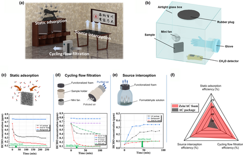
For static absorption testing, the formaldehyde pollution level was recorded after every 10 min. The background without AC material was also tested to test the natural release of formaldehyde of the sealed box. From Figure 6c, one can find that the HCHO pollution level drops very quickly during the first hour of testing for the zein/AC foam and the removing efficiency is about 78.3% after 4 h of testing. In contrast, the HCHO pollution level slowly drops with testing time and the removing efficiency is around 44.2% after 4 h. This static absorption testing result indicates the porous foam structures along with the porous Zein/AC coating is helpful to fast absorb the toxic gases. Figure 6d shows the result comparison by the cycling filtration strategy, where the polluted air is pushed through the filtration material by a mini fan. After about an hour, the removal efficiency reached up to 84.4% for the zein/AC functionalized foam; however, for the commercial AC package, it was about only 38.5%. At the same time, it was found that the HCHO pollution level is stabilized at a high level (0.4 ppm) after about an hour. On the contrary, it was brought down to the standard level around 0.1 ppm by the zein/AC functionalized foam after an hour. This result further reveals that the absorption capacity of the zein/AC foam is also much higher than that of the commercial AC package. It should be noted that the zein protein as the binder also enhances the toxic gas absorption capability. By comparing with traditional polymer binder poly(vinyl acetate, PVAc), the zein protein itself shows formaldehyde adsorption capability (Figure 6d). Source interception is believed a very effective strategy for indoor air-quality control. As illustrated in Figure 6e, formaldehyde solution was sealed inside a glass bottle by the filter material. With the evaporation, formaldehyde molecules must travel through the filter material to diffuse into the air outside. A high-performance filter material should be able to absorb most of the formaldehyde molecules before they spread out into the air. It can be found that the formaldehyde pollution level rises rapidly for the background testing and the testing with the commercial AC package, although the commercial one did help a little bit. For the zein/AC coated foam, the pollution level was successfully controlled below the standard value (0.1 ppm) even after 100 min. For a comprehensive comparison, the absorption efficiency with the above three strategies is compared between the zein/AC coated foam and commercial AC package. As shown by Figure 6f, the zein/AC coated foam shows much higher removing efficiency no matter of the testing methods.
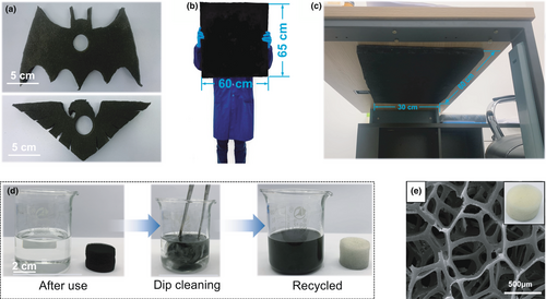
To further demonstrate its possible practical application, Figure 7a exhibits some of the examples on the shape customizability of the zein/AC functionalized PU foam. This may be of great interest as it works as a functional decoration capable of absorbing toxic gases. The shape of the products can be customized on demand. Large-scale fabrication capability was also demonstrated in Figure 7b, where the size of the sample is 600 mm × 600 mm × 20 mm (L × W × T). This big plate-like product was fixed on the back of a new table to absorb the possible VOCs (see Figure 7c) from the air or the inside of the table. Via the above special design of the products, it is possible to realize efficient and long-term control of indoor air quality. Theoretically, the size and geometry of the zein/AC functionalized PU foam should not be limited by the above demonstration. Finally, the recyclability of the heavy functionalized PU foam was investigated as shown by Figure 7d. Recyclability is of great interest with the increasing global concern on the plastic pollution. For the zein/AC coated PU foam, the coating layer can be simply removed by the ethanol/water mixture solvent. As shown by Figure 7d, the foam, as well as the AC active material, is easily separated by dip cleaning with the mixture solvent. The recycled foam skeleton is almost the same as the original one (see Figure 7e). It should be noted that the AC active material could also be recycled if one can convert the absorbed toxic gases into non-toxic chemicals.
3 Conclusion
In summary, a general heavy coating strategy for cost-effective functionalization of polymer foams is successfully demonstrated for efficient indoor air-quality management. The heavy coating is realized by the design of functional sticky jammed fluids (SJFs) inspired by electrode slurry. To realize a uniform and thick coating onto porous 3D foam, a mechanic-assisted micro-adhesion guided (MAG) coating strategy is further developed in this study. Results show that the status of zein protein chain as adjusted by the solvent composition plays a critical role in controlling the interface binding with the PU skeleton. To achieve stable and porous coating for better absorption performance, the optimal mass ratio between zein binder and active material (active carbon in this study) is determined to 20: 80. Meanwhile, the optimal solid concentration of the SJFs was found around 30 wt% to simultaneously realize good processing feasibility and a high coating efficiency. Results further reveal that the heavy functional coating not only notably improves the mechanical strength of the composite foam, but also brings forth advanced formaldehyde absorption capability under different situations. Finally, shape customizability, large-scale fabrication, and application, as well as feasible recyclability are demonstrated for its practical applications. This work not only provides a very promising zein/AC functionalized foam for indoor air-quality control, but also a general strategy for heavy functional coating of porous substrates, based on the design of sticky jammed fluids as well as the mechanic-assisted MAG technology.
4 Experimental Section
Materials and composition optimization
Zein was obtained from Shanghai Naijing Industry Co., Ltd. Active carbon powder (YEC-8A) was purchased from Alibaba. PU foam (60 ppi) was purchased from Alibaba. To study the adhesion properties of zein with the PU foam, zein solutions with 5 wt% solid concentration were prepared in a mixture solvent with different ethanol: DI volume ratios (3: 1, 6: 1, and 9: 1). To prepare the zein/AC slurry, zein solutions with a solid concentration of 25 wt% were prepared in the mixture solvent with an optimized ethanol: DI volume ratio (9: 1) for achieving the strongest zein/PU interactions. The solutions were stirred at room temperature with a speed of 720 rpm for 30 min to achieve homogeneous solution. To prepare the zein/AC slurry with a constant solid concentration (30 wt%) but different zein: AC ratios (80: 20, 65: 35, 50: 50, 35: 65, 20: 80, and 10: 90, respectively), the zein powder was mixed with AC particles according to the above ratios first. Then, the mixture powder was stirred inside the optimized mixture solvent at room temperature at 720 rpm for 30 min to achieve homogeneous slurry. Meanwhile, PU foam was cut into cylinder with a diameter of 25 mm and a thickness of 20 mm. The slurries with different compositions were then coated onto the PU foam by the proposed mechanical-assisted micro-adhesion guided (MAG) coating technology. Then, the samples were dried inside an oven at 60 °C for 1 h. To optimize the solid concentration of the SJF, zein/AC mixture with an optimized weight ratio of 2:8 was dissolved and dispersed into the mixture solvent with different solid concentration (20 wt%, 25 wt%, 30 wt%, 35 wt%, and 40 wt%). The slurries were stirred at room temperature at 720 rpm for 30 min to achieve homogeneous dispersion.
Preparation of zein/AC heavy-coated foam
Characterizations
The morphology of all the samples was characterized by FEI-INSPECTF scanning electron microscopy (SEM, Hillsboro, OR, USA). To study the effects of solvent composition on the interaction between zein and PU plate, peeling-off test was performed by an advanced rheometer (AR2000EX, TA instrument, USA). The peeling rate was 500 μm s−1, and the peeling angle was maintained at 180°. Rheological properties of the SJFs with different solid concentration were tested by the same rheometer mentioned above. The strain was set at 10%, and the frequency range was from 100 to 0.05 Hz. The drying rheological properties test was performed via a specially designed sample holder (see Figure 4b) with a strain of 10% and frequency of 5 Hz by the above rheometer at room temperature. Compression testing of the foams was also performed by the above rheometer with a compression speed of 300 μm s−1.
Pressure drop and air-purification test
The pressure drop of samples was measured by a pressure meter (CEM, DT-8920, China). The air-flow rate was 30 cm s−1 which is controlled by an air flowmeter (SENLOD, LZB-10, China). The polluted air was created by the volatilization of a dilute formaldehyde solution (0.37 wt%) in the airtight glass box. The formaldehyde concentration was measured by a particle counter (Korno, GT-1000-CH2O) with HCHO chemical sensors (accuracy of 0.01 ppm). 1) Static adsorption testing. 50 μL of the dilute formaldehyde solution was dropped onto a glass slide in the airtight box to simulate a HCHO-polluted room. The absorption sample was then taken out from a hermetic bag that is already put inside the box, when the formaldehyde level reached a stable value. Then, the HCHO concentration was recorded every 10 min to track the absorption until the concentration reached another stable value. In order to exclude the possible leakage effect, the HCHO concentration was also recorded every 10 min for the box without any absorption materials. This is called background testing that was also used for the following testing. 2) Cycling flow filtration testing. The preparation of polluted air is the same as above. Samples of zein/AC foam, zein-coated foam, and PVAc-coated foam were cut into cylinder with the size of 40 mm × 20 mm (diameter × thickness) for the test. Commercial AC particle was sealed into package with the same size to achieve the same volume with the functionalized foam. The absorption sample was taken out from a hermetic bag and assembled within a mini fan to create cycling air flow. 3) Source interception testing. For this testing, 50 μL of the dilute formaldehyde solution was put into a glass bottle and the absorption sample was placed on a screen cloth, which block the diffusion of polluted air as illustrated in Figure 5e. The recording of the HCHO concentration was all conducted after every 10 minutes until an equilibrium state is reached.
Acknowledgements
Y.J. and L.J. contributed equally to this work. This research is sponsored by the Double First-Class Construction Funds of Sichuan University and National Natural Science Foundation of China (NNSFC). The authors also gratefully acknowledge the financial support from the National Natural Science Foundation of China (NNSFC grants 51873126, 51422305, and 51721091).
Conflict of Interest
The authors declare no conflict of interest.


