Tailoring Mg2+ Solvation Structure in a Facile All-Inorganic [MgxLiyCl2x+y·nTHF] Complex Electrolyte for High Rate and Long Cycle-Life Mg Battery
Abstract
A high-performance all-inorganic magnesium–lithium chloride complex (MLCC) electrolyte is synthesized by a simple room-temperature reaction of LiCl with MgCl2 in tetrahydrofuran (THF) solvent. Molecular dynamics simulation, density functional theory calculation, Raman spectroscopy, and nuclear magnetic resonance spectroscopy reveal that the formation of [MgxLiyCl2x+y·nTHF] complex solvation structure significantly lowers the coordination number of THF in the first solvation sheath of Mg2+, which significantly enhances its de-solvation kinetics. The MLCC electrolyte presents a stable electrochemical window up to 3.1 V (vs Mg/Mg2+) and enables reversible cycling of Mg metal deposition/stripping with an outstanding Coulombic efficiency up to 99% at current densities as high as 10 mA cm−2. Utilizing the MLCC electrolyte, a Mg/Mo6S8 full cell can be cycled for over 10 000 cycles with a superior capacity retention of 85 mA h g−1 under an ultrahigh rate of 50 C (1 C = 128.8 mA g−1). The facile synthesis of high-performance MLCC electrolyte provides a promising solution for future practical magnesium batteries.
1 Introduction
Magnesium (Mg) as a metal anode can afford nearly twice the volumetric capacity than that of lithium (3833 vs 2062 mA h cm−3) and possesses several unique advantages such as low cost and safety.[1, 2] In research of rechargeable Mg batteries, developing suitable electrolytes is pivotal. Over the past decades, intensive efforts have been invested in finding high-performance Mg2+ electrolytes.[3-12] However, it is still challenging to develop an electrolyte that simultaneously possesses advantages of simple, low-cost, and high efficiency. Among the electrolytes that have been developed, the all-inorganic Mg2+ electrolyte is particularly attractive due to its simplicity and broad application prospects. The first successful all-inorganic electrolyte is synthesized by reacting MgCl2 with a Lewis acid of AlCl3, which is capable of stripping/plating Mg, non-nucleophilic (compatible with sulfur) and delivers an electrochemical window of nearly 3 V (vs Mg/Mg2+).[13-15] Such electrolyte has been termed as magnesium aluminum chloride complex (MACC),[13] although a later study by single-crystal X-ray diffraction indicates that it is actually composed of the dimer cations, [Mg2Cl3(THF)6]+, and the AlCl4− anions.[14] Despite of the advantages, a tedious conditioning process is required before a reasonable reversibility of Mg stripping/plating can be achieved in MACC, and its electrochemical activity may decay again with time.[16, 17] Toxic CrCl3,[18] Mg powders,[17] and high-cost MgTFSI2[19] have been added in MACC to relieve its onerous electrochemical activation process. Another problem of the MACC electrolyte is the inevitable co-deposition of Al during Mg plating, as a result of a higher reduction potential of Al (−1.66 V vs NHE) than that of Mg.[13] To address this issue, AlCl3 has been replaced by YCl3 because Y has a lower reduction potential of −2.372 V (vs NHE).[20] Despite the complicated preparation procedures that require 120 °C synthesizing temperature and PYR14TFSI cosolvent, MgCl2-YCl3 complex solution delivers a relatively lower overpotential of ±110 mV (at 0.5 mA cm−2) for Mg stripping/plating without Y co-deposition and an electrochemical window of 3.0 V (vs Mg/Mg2+). Nevertheless, a conditioning process is still required for MgCl2-YCl3, and its solution structure is not clear yet. Therefore, the search for new high-performance all-inorganic Mg electrolyte is still critically needed.
Solvation chemistry plays a pivotal role in reactions on electrode surfaces and ultimately affects the performance of Mg batteries. Tailoring the solvation structure of an electrolyte is an effective way for improving the reversibility of metallic anodes. LiCl has long been considered as an efficient additive in organic synthetic chemistry, partially due to its high solubility in organic solvents, and the reduction potential of Li+ (−3.04 V vs SHE) is much lower than that of Mg2+, which eliminates the possibility of Mg-Li co-deposition. Previously, we reported that 1 M addition of LiCl to a MACC electrolyte ([Mg(THF)6][AlCl4]2/PYR14TFSI/THF) could dissolve the absorbed MgCl2 on electrode/electrolyte interface and significantly reduce the polarization of Mg platting/stripping.[9] However, the complicated preparation method and the use of high-cost ionic liquid make it less attractive for practical applications, and the detailed electrolyte solvation structure has not been studied. In this work, using a solvation structure tailoring strategy, a highly efficient all-inorganic magnesium electrolyte was synthesized by a simple room-temperature reaction of LiCl with MgCl2 in THF solvent. Raman spectroscopy, nuclear magnetic resonance (NMR) spectroscopy, density functional theory (DFT) calculation, and molecular dynamics (MD) simulation revealed that a complex of [MgxLiyCl2x+y·nTHF] aggregate was formed in the solution owning to the interplay of Mg2+, Cl−, and Li+ in THF. We therefore refer this electrolyte as magnesium–lithium chloride complex (MLCC). Importantly, the coordination number (0.67) of THF in the first solvation sheath of Mg2+ in MLCC (0.3 M) is much lower than that (2.5) in MgCl2/THF solution (0.3 M), which leads to a significantly enhanced de-solvation kinetics of Mg2+. This MLCC electrolyte possessed a stable electrochemical window up to 3.1 V (vs Mg/Mg2+) and enabled reversibly cycling of Mg stripping/plating at a high current density of 10 mA cm−2 with an outstanding Coulombic efficiency (CE) up to 99%. Using this electrolyte, a Mg/Mo6S8 full cell can be cycled for over 10 000 cycles with a superior capacity retention of over 85 mA h g−1 under an ultrahigh rate of 50 C. To our knowledge, this performance is the best among reported so far for all-inorganic Mg2+ electrolytes (Table S1).
2 Results and Discussion
To evaluate the Mg stripping/plating behavior in all-inorganic MLCC electrolytes, cyclic voltammetry (CV) and linear sweep voltammetry (LSV) measurements were performed using electrolyte samples prepared with different Mg2+:Li+ ratios (Figure 1a,b). For comparison, a control sample of pure MgCl2 solution in THF was also tested, where its CV showed low redox peaks, indicating its poor Mg stripping/stripping capability (Figure 1a). In stark contrast, significantly pronounced redox peaks were obtained with increasing Li+ ratio. Considering the solubility issue, the highest Mg2+:Li+ molar ratio was limited to 2:4 in our experiments, which gave the lowest overpotential and the largest peak current density. The molar ratio of Mg2+ and Li+ also impact the oxidative decomposition voltage of the MLCC electrolytes, as shown in the LSV results (Figure 1b). The control sample of pure MgCl2 solution displayed an electrochemical window of close to 3.5 V (vs Mg/Mg2+). With increasing Li+ ratio, the electrochemical window showed a slight decrease to 3.3, 3.1, and 2.8 V for Mg2+:Li+ = 2:2, 2:3, and 2:4, respectively.
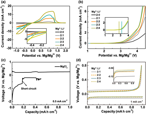
Mg/Cu cells were used to further examine the overpotential and CE of the Mg plating/stripping processes in MLCC electrolytes (Figure 1c,d). The pure MgCl2 control sample displayed a high Mg plating overpotential of 800 mV at the current density of 0.5 mA cm−2 and a short-circuit event occurring at 0.2 mA h cm−2 capacity (Figure 1c). In contrast, MLCC electrolytes significantly alleviated the polarization and avoided short circuit (Figure 1d). At a higher current density of 1 mA cm−2, the Mg plating overpotential in MLCC electrolytes with Mg2+:Li+ = 2:1, 2:2, 2:3, and 2:4 were only 121, 85, 79, and 73 mV, respectively. Nearly 100% CE was achieved in MLCC electrolytes as shown in Figure S1. These showed a great promise of MLCC electrolytes for practical Mg batteries. Considering the overall electrochemical performance, we chose the MLCC electrolyte with Mg2+:Li+ = 2:3 and a Mg2+ concentration of 0.3 M (Figure S2) as the optimal sample for further characterization.
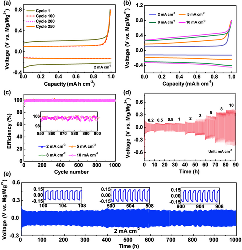
Figure 2a exhibited the Mg plating/stripping cycling performance of this electrolyte in a Mg/Cu cell at an increased current density of 2 mA cm−2. Note that the overpotential in the first cycle was slightly larger than that of the subsequent cycles, which may be caused by the electrochemically inactive substance absorbed on Mg anode before cycling. The voltage profiles were quite stable afterward with a low deposition overpotential of only 124 mV for over 250 cycles. Increasing the current density to 5, 8, or even as high as 10 mA cm−2, despite of the increased polarization voltage (Figure 2b), Mg/Cu cells with the MLCC electrolyte could cycle stably for over 1000 cycles with a CE >99.0% (Figure 2c). The cycling stability of the MLCC electrolyte was further tested in a Mg/Mg symmetrical cell under different current densities from 0.2 to 10 mA cm−2 (Figure 2d). A Mg/Mg cell with the MLCC electrolyte demonstrated an ultralong cycle life for over 1000 h at 2 mA cm−2, with an average overpotential of <150 mV (Figure 2e), which outperform that of MACC electrolyte (Figure S3). Similar stable cycling results were achieved for higher current densities of 5 and 8 mA cm−2 (Figure S4). Notice that the cycle life of 300 h at 8 mA cm−2 corresponds to 1200 cycles (Figure S4b), which illustrates the excellent rate performance of the MLCC electrolyte.
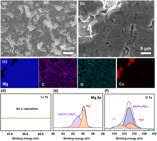
The Mg deposit on Cu electrode obtained from an 1-h plating process in the optimal MLCC electrolyte at 0.5 mA cm−2 showed relatively dense morphology without dendrite formation (Figure 3a,b). The elemental mapping results by energy-dispersive X-ray spectroscopy (EDX) indicated that the deposit was Mg with a small amount of oxygen and carbon as surface contaminants (Figure 3c). The much lower reduction potential of Li should exclude its co-deposition with Mg. To experimentally verify this, X-ray photoelectron spectroscopy (XPS) was performed and there was no Li detected in the Mg deposit (Figure 3d). The Mg 2p, O 1s, and C 1s XPS spectra (Figure 3e,f and Figure S5) showed that the O and C surface contaminants were mainly in the forms of MgO, Mg(OH)2, and MgCO3, which may be caused by the brief exposure of the sample to air before measurement, or from minor electrolyte decomposition products.
To investigate the solvation structure of MLCC electrolytes, MD simulations were performed (see SI for simulation details). MD results showed that the addition of Li+ in MLCC induced a complex [MgxLiyCl2x+y·nTHF] aggregate formation (Figure S6), causing a significantly change in the Mg2+ coordination environment (Figure 4a and Figures S7 and S8). Figure S9, Figure 4b–e and Figure S10 showed the radial distribution functions of Mg2+ in MgCl2/THF and MLCC electrolytes with different Mg2+:Li+ ratios. The Mg-OTHF and Mg-Cl peaks in the Mg2+ first solvation sheath represented the direct interaction of Mg2+ with THF and Cl−, respectively. For pure MgCl2/THF (Figure S9), there were 2.5 THF on average coordinated with Mg2+ in its first solvation shell. In MLCC electrolytes (Figure 4b–e), the coordination number of oxygen (in THF) in the first solvation shell of Mg2+ was significantly reduced to 1.09, 0.80, 0.67, and 0.54 for Mg2+:Li+ = 2:1, 2:2, 2:3, and 2:4, respectively. The lowered coordination number with THF assured a lower de-solvation energy of Mg2+ in the MLCC electrolytes, which would help its electrochemical kinetics in Mg plating/stripping. These results were consistent with the CV and overpotential measurements. On the contrary, the increased Cl− coordination number in the first solvation sheath of Mg2+ may increase the binding sites for Mg2+ jumping motion in MLCC, thereby further facilitating the electromigration of Mg2+.[21] Raman spectroscopy and 7Li NMR were performed to experimentally investigate the solvation structure of MLCC. In the Raman spectrum of MgCl2/THF control sample (Figure 4f), the Raman bands at 280, 600, and 671 cm−1 were from THF solvent, while the characteristic peak at 212 cm−1 was attributed to the undissociated MgCl2.[22] In the spectra of MLCC electrolytes with increasing Li+ ratios, the intensity of this MgCl2 peak decreased gradually, while a Raman peak appeared at 183 cm−1 that corresponded to LiCl.[9] Noticeably, a new weak Raman band at 230–258 cm−1 also appeared. The emergence of the new Raman feature provided strong evidence that the MLCC electrolytes were not a simple mixture solution of MgCl2 and LiCl; instead, there was a chemical reaction that resulted in a new structure in MLCC.
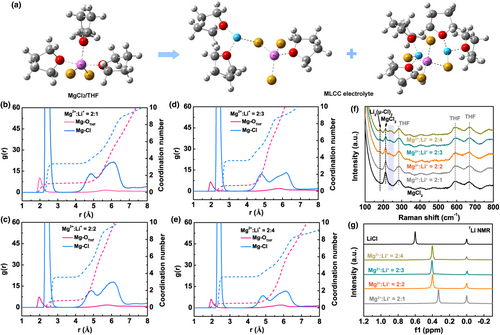
Previous studies on chloride-based magnesium electrolytes normally attributed the Raman feature at 230–258 cm−1 to the complex [Mg2(μ-Cl)3·6THF]+ species.[22, 23] In MLCC electrolytes, however, the formation of [Mg2(μ-Cl)3·6THF]+ would require the first-step reaction of MgCl2 and LiCl to form [MgCl·3THF]+ (Table S2).[14] The calculated free energy increase for this reaction was too high (43.1 kcal/mol) to allow it to happen at room temperature, thus prohibiting the formation of [Mg2(μ-Cl)3·6THF]+ in MLCC. From our MD simulation results, we could disassemble the aggregated Mg-Cl-Li solvation structure in MLCC electrolytes into clusters of a ([Mg2LiCl5·4THF), b ([MgLi2Cl4·5THF]), and c ([Mg2Li3Cl7·7THF]) as shown in Figure S11 and calculate their Raman modes using DFT method. As listed in Table S3, the Mg-Cl stretching modes for clusters a, b, and c were calculated at 234.19, 254.68, and 231.55 cm−1, respectively, which were consistent with the experimental Raman features at 230–258 cm−1. Therefore, the Raman experiment well supported the MD simulated solvation structure in MLCC.
Figure 4g showed the 7Li NMR spectra of LiCl/THF and MLCC electrolytes with different Mg2+:Li+ molar ratios. The singlet at 0.60 ppm in the spectrum of pure LiCl/THF represented the formation of dimer [Li2(μ-Cl)2·4THF], which was in accord with the previous reports.[24, 25] Singlets with chemical shifts of 0.33, 0.40, 0.41, and 0.41 ppm were also observed in the spectra of MLCC electrolytes with Mg2+:Li+ = 2:1, 2:2, 2:3, and 2:4, respectively. Note that 1) the NMR peaks of all the MLCC samples were relatively shifted to higher field in comparison with that of the LiCl/THF sample; 2) the relative peak-shift decreased with increasing Li+ ratio in the MLCC sample; and 3) the NMR peaks of MLCC samples were slightly wider than that of the LiCl/THF sample. In order to correlate the NMR results with our MD simulated solvation structure, we used DFT method to calculate the 7Li NMR chemical shifts of clusters a, b, and c relative to that of the dimer [Li2(μ-Cl)2·4THF]. As shown in Table S3, the calculated relative shifts were all negative and <0.4 ppm, in agreement with the experimental NMR results of MLCC samples where the NMR peaks were in higher field in comparison with that of [Li2(μ-Cl)2·4THF]. MD simulation results showed that MLCC with increasing Li+ ratio contained less cluster a (displaying NMR at higher field) but more clusters b and c (displaying NMR at slightly lower field), also in agreement with the experimental observation in Figure 4g. Although the calculated adjacent peaks of clusters b and c seemed to be inconsistent with the experimental observation of singlets in MLCC samples, it could be explained by the fast conversion among multiple structures, where the exchange rate among different structures was faster than the difference in multiple peak centers, and hence resulted in a wider singlet peak (Figure 4g).[26]
According to the experimental and calculation results, the MLCC solvation structure is in the form of [MgxLiyCl2x+y·nTHF] aggregates, and the formation of this local aggregation structure significantly decreases the coordinated number of THF in the first solvation sheath of Mg2+. Past reports showed that replacing the coordinated solvents of metal ions with anions could facilitate reduction in metal ions at metal surface under the influence of the electric field.[27-32] In Figure S12 and Table S4, we give an estimation of the binding energies of Mg-Cl and Mg-OTHF in [MgxLiyCl2x+y·nTHF] (see Supporting Information for details). Under certain assumptions, the difference between Mg-Cl-Mg and Mg-OTHF binding energies is small, and the dissociation of the former could be assisted by electric field. In this situation, Mg2+ ions become surrounded with three Cl− and one or even zero THF molecule (Figure S12a), making the Mg2+ easier to be reduced (Figure S12c). However, for MgCl2/THF electrolyte, although Cl− will be expelled away from the electrode/electrolyte interface (but still close to Mg2+), more coordinated THF molecules with large volume cause larger steric hindrance, making the Mg2+ more difficult to accept the electron and to be reduced (Figure S12b).
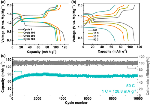
To further demonstrate the merit of fast de-solvation kinetics of the MLCC electrolyte, high-rate performance of Mg/Mo6S8 full cells was tested. The cell was assembled using a Mo6S8 cathode (areal density, 0.65–0.7 mg cm−2), a Mg foil anode, and a Whatman glass fiber separator. In this full cell, it should be noted that the anode undergoes Mg stripping and plating during cycling, while the Mo6S8 cathode may mainly involve Li+ intercalation as previously reported for mixed cation system.[7] As shown in Figure S13, the Mg/Mo6S8 cells could be cycled for over 1000 cycles at the high current density of 5, 10, and 20 C (1 C = 128.8 mA g−1) with a high CE (>99%). The slight increase in discharge capacity might due to a slow wetting process of the electrolyte and/or an activation process of the passivation layer on the Mg anode surface.[7] Figure 5a showed the galvanostatic charge/discharge profiles of the 1st, 100th, 300th, and 500th cycles at 5 C. The Mg/Mo6S8 cell delivered an initial discharge specific capacity of 120.7 mA h g−1 and retained 110 mA h g−1 after 300 cycles, indicating a high electrochemical reversibility. Figure 5b showed the galvanostatic charge/discharge curves of the 200th cycles at different rates. Although the discharge plateau was lower as the current density increased, the small voltage hysteresis reflected the good rate performance of the Mg/Mo6S8 cells with the MLCC electrolyte. In Figure 5c, an ultralong cycle life of a Mg/Mo6S8 cell was demonstrated at an ultrahigh current density of 50 C. After 10 000 cycles, the specific discharge capacity was stably maintained above 85 mA h g−1 with a CE close to 100%. As far as we know, this is the best rate performance among Mg/Mo6S8 cells reported so far (Figure S14, including mixed Mg+/Li+ systems).[7] It should be noted that our key conclusion on the role of Mg2+ solvation structure in MLCC for efficient Mg plating and striping is strongly supported by the results of Mg/Mg symmetric cells, which do not involve Li intercalation reaction or Li plating; and the excellent performance of the full cell is just another support of MLCC's advantages.
3 Conclusions
In conclusion, an all-inorganic MLCC electrolyte was synthesized by a reaction of MgCl2 and LiCl salts in THF solvent at room temperature. Using this electrolyte, highly reversible Mg deposition/stripping process, with a CE as high as 99% for over 1000 cycles, was realized in a Mg/Cu cell at a high current density of 10 mA cm−2. A Mg/Mg symmetric cell also demonstrated an ultralong cycle life of over 1000 h at 2 mA cm−2. For the Mg/Mo6S8 full cells using the MLCC electrolyte, a superior capacity retention of 85 mA h g−1 after 10 000 cycles was achieved at an ultrahigh rate of 50 C. Raman spectroscopy and NMR characterizations, together with MD simulation and DFT calculation, revealed that the solvation structure of MLCC consisted of [MgxLiyCl2x+y·nTHF] aggregates owing to the interplay of Mg2+, Cl−, and Li+ in THF. This aggregated structure significantly reduced the number of coordinated THF molecules in the first solvation sheath of Mg2+ and thus reduced its de-solvation energy and boosted its electrochemical kinetics. This well explained the excellent rate performance of the MLCC electrolyte.
4 Experimental Section
Synthesis of MLCC electrolytes
Anhydrous magnesium chloride (MgCl2, 99.99%) and lithium chloride (LiCl, 99.995%) were purchased from Alfa and used as received. Anhydrous tetrahydrofuran (THF) was purchased from Suzhou Fosai new material Co., Ltd and used as received. MgCl2 (285.6 mg), different quality of LiCl (63.5, 127.11, 190.7, 254.2 mg, respectively), and Mg chips (5 mg/mL) were mixed in THF and stirred overnight at room temperature; then, the solutions were filtered, and MLCC electrolytes with different Mg2+:Li+ ratios (2:1, 2:2, 2:3, and 2:4, respectively) were obtained. MgCl2 (285.6 mg) and Mg chips (5.0 mg/mL) were added in THF and stirred overnight at room temperature; then, the solution was filtered, and a clean MgCl2/THF solution was obtained. The concentration of Mg2+ in MLCC electrolytes is 0.3 M. It is worth noting that the concentration of Mg2+ in the MgCl2/THF electrolyte actually cannot reach 0.3 M due to the low solubility of MgCl2 in THF, and the undissolved MgCl2 has been filtered during the experiment. The added Mg chips were used to remove the impurities in solvent or reactants. The 0.3 M MLCC has a reasonable ionic conductivity of 1.438 mS cm−1 at room temperature, higher than that (0.0155 mS cm−1) of the MgCl2/THF electrolyte.
Electrochemical measurements and characterization of electrolytes
Cyclic voltammetry (CV) and linear sweep voltammetry (LSV) measurements were performed using Pt as the working electrode, and Mg foils as the counter and reference electrodes. The scan rate was 25 mV s−1. CV curves and LSV profiles were both obtained on VMP-3 electrochemical workstation (Bio-Logic, France). The voltage profiles of Mg plating/stripping were evaluated using 2025-type coin cells (Mg/Cu and Mg/Mg) on a Land CT2001 automatic battery tester at room temperature. A Whatman glass fiber separator (GF/A) was used and 100 μL electrolyte was injected in each cell. For Mg/Cu cell, Mg was deposited on Cu foil at different current densities with the capacity of 1 mA h cm−2 each cycle, and then, Mg was dissolved till the voltage achieved 0.8 V (vs Mg/Mg2+). Mg deposit on Cu electrode was obtained in coin-type Mg/Cu cells and was characterized by ESEM (Sirion 200) and XPS (PHI Quantera II). Before testing, Mg deposit on Cu electrode was rinsed by THF for several times to remove the residue of electrolytes. Raman spectra of electrolytes were collected by a JY spectrometer using He-Ne laser of 633 nm in sealed quartz cuvettes. 7Li NMR data were collected by a 600 MHz Bruker AVANCE spectrometer in d8-THF with LiCl in D2O (δ = 0) as the reference standard.
Fabrication of Mg/Mo6S8 cell
Mg/Mo6S8 cells were assembled in the glove box with 2032 coin-type configuration. The cells used polished Mg foils (15 mm in diameter) as anode, Whatman glass fibers (19 mm. dia., GF/B) as separator, and Mo6S8 (10 mm. dia.) as cathode. MLCC electrolyte of 160 μL was injected in each cell. The Mo6S8 cathode was prepared by mixing 70% Mo6S8, 20% Super P, and 10% poly(vinylidene fluoride) (PVDF) in N-methylpyrrolidinone (NMP) to form a slurry using a mortar and pestle. The resulting slurry was spread on a pyrolytic graphite foil and dried under vacuum at 50 °C for 48 h. The areal density of Mo6S8 was around 0.65–0.7 mg cm−2.
Theoretical calculations
Molecular dynamic simulations. The molecular dynamic (MD) simulations were performed using GROMACS 2018.8 package. General amber force field (GAFF) was applied to all atoms and interatomic interactions. The simulation cell was a cubic box size 8 × 8 × 8 nm3. The concentration of Mg2+ was fixed on 0.3 M, while the concentration of Li+ and Cl− varied according to the MgCl2/LiCl ratio. PME method was used to calculate the long-range electrostatic interactions with a cutoff distance of 1.2 nm and a grid spacing of 0.3 nm. Periodic boundary conditions were applied for all three directions. Firstly, an energy minimization was preformed to ensure that all molecules were in reasonable distances. NPT simulations were performed for 2 ns with a time step of 1fs to reach proper densities of all systems. V-rescale thermostat and Berendsen barostat were employed to maintain the temperature at 298 K and pressure at 1 atm respectively. After a 2 ns NVT simulation, data collections and analysis were based on a following NVT simulation for 10 ns.
Raman and 7Li NMR chemical shifts
Raman spectra and the NMR chemical shifts were calculated using Gaussian 16 c.01 package. Initial structures were extracted from MD trajectories. M062X/6-311++g (d, p) level of theory was used for both structure optimization and frequency calculation. To obtain 7Li NMR chemical shift, the gauge independent atomic orbital (GIAO) method was employed at B972/def2TZVP theory level. THF solvent effect was considered implicitly using SMD method in all calculations.
Acknowledgments
This work was supported by the National Natural Science Foundation of China (NSFCU1832218) and the Beijing Advanced Innovation Center for Future Chip (ICFC). H. Fan and X. Zhang contributed equally to this work. The authors thank Dr. Y. Ye for XPS analyses and offering helpful discussions.
Conflict of Interest
The authors declare no conflict of interest.


