P2-Na2/3Ni2/3Te1/3O2 Cathode for Na-ion Batteries with High Voltage and Excellent Stability
Abstract
Air-stable layered structured cathodes with high voltage and good cycling stability are highly desired for the practical application of Na-ion batteries. Herein, we report a P2-Na2/3Ni2/3Te1/3O2 cathode that is stable in ambient air with an average operating voltage of ~3.8 V, demonstrating excellent cycling stability with a capacity retention of more than 92.7% after 500 cycles at 20 mA g−1 and good rate capability with 91.9% capacity utilization at 500 mA g−1 with respect to capacity at 5 mA g−1 between 2.0 and 4.0 V. When the upper cutoff voltage is increased to 4.4 V, P2-Na2/3Ni2/3Te1/3O2 delivers a reversible capacity of 71.9 mAh g−1 and retains 91.8% of the capacity after 100 cycles at 20 mA g−1. The charge compensation during charge/discharge is mainly due to the redox couple of Ni2+/Ni3+ in the host with a small amount of contribution from oxygen. The stable structure of the material without phase transformation and with small volume change during charge-discharge allows it to give excellent cycle performance especially when the upper cutoff voltage is not higher than 4.2 V.
1 Introduction
Na-ion battery (NIB) is a promising alternative to Li-ion battery for energy storage system, mainly due to the earth-abundant, uniformly distributed, and cost-effective sodium resources. However, the practical application of NIB is greatly limited by the availability of cathode materials with both high energy density and long cycle life.[1-4]
Among various cathode candidates, P2-type layered transition metal oxides (i.e., NaxMO2) have attracted most attention due to their fast Na+ diffusion, high theoretical capacity of larger than 200 mAh g−1 and high volumetric capacity.[5-8] In particular, P2-NaxMnO2 that relies on environmentally friendly Mn has been extensively studied in the past few years.[9-13] However, P2-NaxMnO2 utilizes Mn2+/Mn3+ and Mn3+/Mn4+ redox couples with low average operating potential (<3.0 V vs Na/Na+), so the available energy density of the NIB full cell is low. Substituting nickel in P2-NaxMnO2 is one of the effective approaches to raise the operating potential by making use of Ni2+/Ni3+ and Ni3+/Ni4+ redox couples.[12, 14, 15] As an extreme example, P2-Na2/3Ni1/3Mn2/3O2 cathode that solely depends on Ni2+/Ni3+ and Ni3+/Ni4+ redox couples (i.e., charges/discharges in the voltage range of 2.5–4.4 V) presents a high average potential of ~3.8 V, which significantly increases the energy density of NIB full cell.[16-18] However, the high energy density requires the utilization of 2/3 mol Na+ per mole of P2-Na2/3Ni1/3Mn2/3O2, resulting in the formation of Ni4+ at charged state with localization of electrons around the nickel ions, thus weakening the bonding between nickel and oxygen, which in return leads to the migration of nickel ions to sodium layer as well as the release of oxygen.[19, 20] These phenomena are verified as the major causes of the poor cycle stability of P2-Na2/3Ni1/3Mn2/3O2 with a high cutoff voltage (i.e., 4.4 V). An effective approach to improve the life cycle of P2-Na2/3Ni1/3Mn2/3O2 is to only make use of Ni2+/Ni3+ redox couple via lowering the upper cutoff voltage to 4.0 V.[21, 22] Nevertheless, the improvement of the cycle stability is at the expense of reversible capacity (i.e., the reversible capacity is reduced from ~165 to ~80 mAh g−1 by lowering the upper cutoff voltage from 4.4 to 4.0 V).
To solve the dilemma, we propose to increase nickel content via replacing Mn4+ with high valence ions, that is Te6+, to form P2-Na2/3Ni2/3Te1/3O2 (also can be written as Na2Ni2TeO6), so that we can utilize all of the Na+ in the cathode host without formation of Ni4+. The sodium storage performance of P2-Na2/3Ni2/3Te1/3O2 has been preliminarily investigated by Goodenough’s group in 2013.[23] They demonstrated that this material can deliver a high reversible capacity of ~110 mAh g−1 at a current density of ~4 mA g−1 in voltage range of 2.0–4.5 V. On the other hand, little is known about its rate capability, air stability, charge compensation mechanism, and structural evolution upon charge/discharge process.
Herein, the air stability, structural and electrochemical performance of P2-Na2/3Ni2/3Te1/3O2 cathode were comprehensively investigated. P2-Na2/3Ni2/3Te1/3O2 delivers excellent cycle stability. In the voltage ranges of 2.0–4.0 and 2.0–4.2 V, the material retains more than 88% of the initial reversible capacity after 500 cycles at 20 mA g−1. Even in the voltage range of 2.0–4.4 V, the material shows a capacity retention of ~79.2% after 300 cycles at 20 mA g−1. It also gives superior rate capability. When tested in the ranges of 2.0–4.0 and 2.0–4.2 V, more than 91.9% of the discharge capacity can be retained when the discharge current density is increased from 5 to 500 mA g−1, while between 2.0 and 4.4 V, the high-current utilization rate is ~69.3%. Interestingly, X-ray diffraction studies indicate that there is no significant change in lattice constants of the material during de-sodiation even up to 4.4 V. Thus, the reduced electrochemical performance with a 4.4 V cutoff is mainly attributed to exfoliation of the layered structured cathode at high voltage.
2 Results and Discussion
2.1 Material Characterization
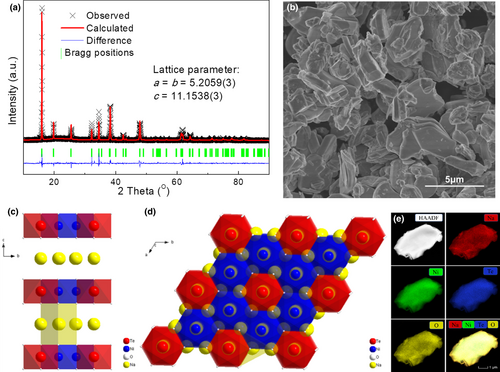
The XRD of the as-prepared Na2Ni2TeO6 was collected to investigate its crystal structure. As shown in Figure 1a, the XRD pattern can be indexed to the hexagonal structure with a space group of P63/mcm. Based on the Rietveld refinement, the lattice parameters are determined as a = b = 5.2059(3) Å and c = 11.1538(3) Å, which is in good agreement with previous literatures.[23, 24] The crystal structure of Na2Ni2TeO6 is composed of layered stacking of Na and Ni/Te-O (Figure 1c), where the Ni/Te-O layer shows a honeycomb arrangement that consists of edge-sharing NiO6 octahedra with TeO6 at the center (Figure 1d). SEM image (Figure 1b) reveals that the as-prepared Na2Ni2TeO6 is in general micron-sized plate-like particles with sizes ranging from 2 to 5 µm. Their morphology is consistent with its layered structure. The uniform distribution of the compositional elements is clearly revealed by the EDX mapping of a single Na2Ni2TeO6 particle (Figure 1e). The composition of the sample is confirmed to be Na1.995Ni2Te0.990O6 by ICP-MS, which is very close to the expected stoichiometry (Table S1, Supporting Information).
2.2 Electrochemical Performance
The CV tests in different voltage ranges (i.e., 2.0–4.0 V, 2.0–4.2 V, and 2.0–4.4 V) were conducted to understand the electrochemical reaction of Na2Ni2TeO6 electrode at a scanning rate of 0.1 mV s−1 (Figure 2a). Between 2.0 and 4.0 V, the material shows four pairs of strong oxidation/reduction peaks, demonstrating the highly reversible redox reaction during charge/discharge process. The voltage difference of 1st pair of peaks is ~0.14 V and the voltage difference of other three pairs of peaks is less than 0.05 V, which clearly indicates the fast electrochemical reaction kinetics. When the upper cutoff voltage is extended to 4.2 V, an additional pair of redox reaction peaks is observed at ~4.13 and ~4.08 V. Peak positions of the remaining peaks are about the same, suggesting no change in charge-discharge mechanism between a 4.0 and a 4.2 V cutoff. When the cutoff voltage is further extended to 4.4 V, an additional oxidation peak is observed at 4.3 V. Furthermore, the position of some reduction peaks shifts toward lower voltage, indicating the increased polarization when tested in the 2.0–4.4 V range.
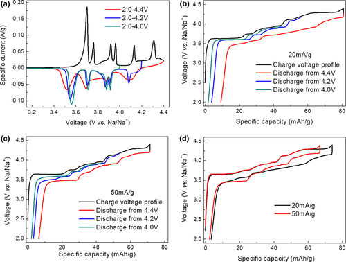
These electrochemical features and the corresponding evolution upon increasing upper cutoff voltages are fully consistent with the charge/discharge curves collected at a current density of 20 mA g−1 (Figure 2b). However, we found the voltage profile at 2.0–4.4 V changes from an asymmetric shape for 20 mA g−1 to a symmetric shape for 50 mA g−1 (Figure 2c), although the trend in polarization evolution in general remains the same. To understand the asymmetric charge/discharge profiles, the charge/discharge curves at 20 and 50 mA g−1 are compared in Figure 2d and Figure S2, Supporting Information. The two charging curves at different current rates almost overlap with each other before the voltage plateau at ~4.3 V, indicating a fast reaction kinetic of the material below 4.3 V. On the other hand, the capacity from the 4.3 V-plateau is much higher at a current density of 20 mA g−1, compared to that at 50 mA g−1, which clearly reveals the limited reaction kinetic of the 4.3 V-plateau. Interestingly, the higher capacity obtained during the 4.3 V-plateau at a current density of 20 mA g−1 not only leads to asymmetric discharge profile, but also results in larger voltage hysteresis despite its lower current density. The observed phenomenon suggests that the access to higher capacity at 4.3 V is accompanied by side reactions and possible change of Na+ insertion partway, which in return leads to a sluggish reaction kinetic during the subsequent discharge process. It is worth mentioning that the additional plateau below 3.5 V in discharge profile from 4.2 V (Figure 2c, Figures S1 and S2, Supporting Information) should be caused by the additional polarization originating from Na counter electrode due to the use of FEC in the electrolyte.[25]
The sodium storage performance of Na2Ni2TeO6 was investigated in half-cell using Na metal foil as counter/reference electrode. When cycled in the range of 2.0–4.0 V, the Na2Ni2TeO6 electrode delivers a reversible capacity of ~42.2 mAh g−1 at both current densities of 20 and 50 mA g−1. The electrode shows excellent cycle stability in 2.0–4.0 V regardless of the current densities. Specifically, the Na2Ni2TeO6 electrode can retain ~92.7% of the initial discharge capacity after 500 cycles at 50 mA g−1 (Figure 3a). To increase the capacity of the electrode, the upper cutoff voltage was raised to 4.2 and 4.4 V, respectively. When cycled in 2.0–4.2 V, the electrode delivers higher reversible capacities of ~52.2 and ~50.3 mAh g−1 at 20 and 50 mA g−1, respectively. The Na2Ni2TeO6 electrode still demonstrates good cycle stability (Figure 3b). Higher reversible capacities of ~71.6 and ~65.1 mAh g−1 at 20 and 50 mA g−1 can be achieved when the cutoff voltage is further raised to 4.4 V (Figure 3c). While cycle performance somewhat deteriorates when tested to 4.4 V, Na2Ni2TeO6 still gives a capacity retention of ~79.2% after 300 cycles. The cycle stability of Na2Ni2TeO6 is comparable to the previous reports, despite its micron size (Table S2, Supporting Information). In addition, Na2Ni2TeO6 shows very stable average operating voltages upon extended cycles in voltage ranges of 2.0–4.0 V and 2.0–4.2 V (Figures S3 and S4, Supporting Information). While cycling in 2.0–4.4 V leads to a gradual decay in average operating voltage, suggesting the material may degrade at high voltage, which will be investigated in the later section.
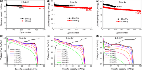
Figure 3d–f displays the typical voltage profiles obtained at different discharge current densities ranging from 5 to 500 mA g−1 with the same charge current density of 5 mA g−1. When tested in the range of 2.0–4.0 and 2.0–4.2 V, the material shows extraordinary rate performance: >91.9% of the discharge capacity can be retained when the discharge current density is increased from 5 to 500 mA g−1, although the polarization gradually increases (i.e., the discharge voltage profiles shift down to lower voltage) upon increase of discharge current densities. Even when cycled between 2.0 and 4.4 V, the electrode can retain ~69.3% of the discharge capacity (i.e., ~56.9 mAh g−1) when the discharge current density is increased from 5 to 500 mA g−1. The rate performance in the range of 2.0–4.4 V is worse than that in 2.0–4.0 V and 2.0–4.2 V (Figure S5, Supporting Information). The polarization in 2.0–4.4 V largely increases upon increase of discharge current densities, especially when the current is larger than 100 mA g−1.
Impedances of the electrodes were taken to study the change in kinetics of the electrode with different charge voltages. Figure S6, Supporting Information shows that the impedance profiles have two semi-circles. The charge transfer resistance (Rct, as reflected by the diameter of second semi-circle) is increased with the increase of charge cutoff voltage, supporting the more sluggish reaction kinetics observed in the charge-discharge tests.
2.3 Air stability
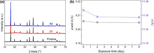
Many layered Na-based transition metal oxide cathodes show poor structural stability against air exposure, which therefore requires a controlled atmosphere during synthesis, electrode preparation, and battery construction if they were to be used for practical applications. In this regard, it is essential to develop cathode materials with excellent stability toward air exposure. Na2Ni2TeO6 is one of such materials. As presented in Figure 4, Na2Ni2TeO6 shows no structural change and no impurity formation even after exposure in air for 8 days. The excellent structural stability of Na2Ni2TeO6 sample is further corroborated by the negligible shrinkage of lattice parameters (<0.05%, Figure 4b) even after air exposure for 8 days, as obtained via Rietveld refinement (Figure S7, Supporting Information). These results clearly demonstrate that there is little reaction between Na2Ni2TeO6 and air (e.g., H2O and CO2), as these reactions will typically lead to the formation of impurities like NaOH and Na2CO3 and the shrinkage of the lattice constants due to the leakage of lattice sodium via Na+/H+ exchange.[26]
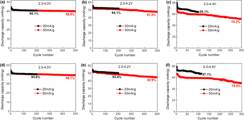
To further demonstrate the superior air stability of P2-Na2Ni2TeO6, the materials after exposure to air for 2 and 8 days were subjected to electrode preparation and electrochemical cycling. As can be seen from Figure 5, the materials after exposure only delivers marginal decay in capacity and capacity retention compared with the pristine material. For example, the capacity retention after 500 cycles in 2.0–4.0 V at 50 mA g−1 only decreases from 92.7% to 89.9% after exposure for 2 days and 89.1% after exposure for 8 days. Even in a tough voltage range of 2.0–4.4 V at 50 mA g−1, the capacity retention after 300 cycles only decreases from 79.2% to 78.2% after exposure for 2 days and 75.8% after exposure for 8 days.
2.4 Charge compensation mechanism and structural evolution
To understand the charge compensation mechanism of Na2Ni2TeO6 cathode, XPS spectra of the electrode at three different charged/discharge states (i.e., pristine, charged to 4.4 V, and after 1 cycle in 2.0–4.4 V) were collected. The Ni 2p3/2 spectrum of pristine electrode (Figure 6a) shows a main peak at ~855.5 eV and a satellite peak at ~861.2 eV, demonstrating the presence of Ni2+ in the sample.[27] On gradual charging to 4.4 V, the main peak shifts to higher binding energy of ~857.9 eV, indicating the oxidation of Ni2+ to Ni3+. While there is a shoulder at ~855.5 eV remaining, suggesting there are un-oxidized Ni2+ remaining in the sample. On discharging to 2.0 V, the binding energy of the peak shifts back to the original position of Ni2+ with only a tiny shoulder at the position of Ni3+, indicating the Ni2+/Ni3+ redox couple are mostly reversible.
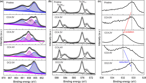
For the Te 3d5/2 spectra (Figure 6b), the pristine Na2Ni2TeO6 material shows a main peak at ~576.3 eV originating from Te6+. The spectra of Te 3d remain invariant during the whole charge/discharge process, which clearly demonstrates that Te does not participate in charge compensation. The pristine material shows a sharp peak at ~530.2 eV for the O 1s spectrum corresponding to lattice O2− (Figure 6c).[28] Upon charging to 4.0 V, the main feature of the O 1s spectrum remains unchanged as the O does not contribute to the charge compensation at this stage. Further charging to 4.2 and 4.4 V, the O 1s spectrum broadens and the peak shifts to a binding energy at ~531.8 eV, which indicates the oxidation of O2−. Upon discharging to 2.0 V, the binding energy of O 1s generally shifts back to its original energy, confirming the subsequent reduction of oxidized O2−. However, the specific index of the oxidized O2− based on the deconvolution of O 1s spectra is not possible due to their poor signal to noise ratio and the formation of cathode electrolyte interphases containing oxygen species, especially at charged state.
To summarize, the Ni2+/Ni3+ redox couple is mainly responsible for the charge compensation during charge/discharge process, while the participation of anionic oxygen is also verified at voltage higher than 4.2 V, which has been reported for other layered oxide cathodes for NIB.[29]
The structural change of the electrode is further characterized by ex-situ XRD. The electrodes were charged to 4.0, 4.2, or 4.4 V and also discharged to 2.0 V, and the electrodes were extracted from the cell for measurement. As shown in Figure 7, no shift of the XRD profiles is observed from Na2Ni2TeO6 at any state of charge. Rietveld refinements of the electrodes are conducted and the parameters are shown in Table 1. Note that the maximum reduction in the lattice constants with de-sodiation is typical <0.13%, indicating small changes of the lattice during charge-discharge. Even after 100 cycles (Figure 7c), the electrodes show the same XRD pattern with minimal crystal structure change despite of the cycled voltage ranges, demonstrating the good stability upon charge and discharge.

| Samples | a = b (Å) (% change from pristine) | c (Å) (% change from pristine) |
|---|---|---|
| Pristine | 5.2059(3) | 11.1538(3) |
| Charged to 4.0 V | 5.2048(6) (−0.02%) | 11.1449(6) (−0.08%) |
| Charged to 4.2 V | 5.2032(7) (−0.05%) | 11.1398(6) (−0.13%) |
| Charged to 4.4 V | 5.2001(3) (−0.11%) | 11.1396(3) (−0.13%) |
| Charged to 4.0 V, discharged to 2.0 V | 5.2037(7) (−0.04%) | 11.1397(9) (−0.13%) |
| Charged to 4.2 V; discharged to 2.0 V | 5.2045(8) (−0.03%) | 11.1435(7) (−0.09%) |
| Charged to 4.4 V; discharged to 2.0 V | 5.2056(8) (−0.01%) | 11.1414(1) (−0.11%) |
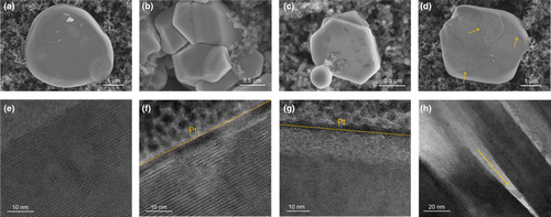
To further reveal the structural stability of Na2Ni2TeO6, SEM and TEM images of the electrodes after 100 cycles were collected. As can be seen from Figure 8, the fresh Na2Ni2TeO6 and the ones after 100 cycles in 2.0–4.0 V show smooth surface with good crystallinity (Figure 8a,b,e,f). Although there are some pits on the surface of Na2Ni2TeO6 after 100 cycles in 2.0–4.2 V, its crystallinity is well maintained. In stark contrast, the Na2Ni2TeO6 after 100 cycles in 2.0–4.4 V possesses a high dense of pits on its surface. Moreover, the trace for exfoliation of the layered structured Na2Ni2TeO6 can be found, which is further evidenced by the HRTEM images (Figure 8h, and Figure S8, Supporting Information). These results clearly demonstrate that the capacity decay in 2.0–4.4 V is rooted from the structural degradation of the materials.
3 Conclusion
Air-stable P2-Na2/3Ni2/3Te1/3O2 cathode with an average operating voltage of ~3.8 V is demonstrated as a stable cathode for Na-ion batteries. It can deliver a reversible capacity of 71.9 at 20 mA g−1 in 2.0–4.4 V and retain more than 79% of the capacity after 300 cycles. When the upper cutoff voltage is lowered down to 4.2 and 4.0 V, the material shows more impressive cycling stability. The stable capacity could be attributed to the well-maintained crystal structure and minor change in lattice constants, as indicated by the XRD studies. In 2.0–4.4 V, both Ni2+/Ni3+ redox and reversible oxygen redox contribute to the capacity of Na2/3Ni2/3Te1/3O2, while its capacity decay is partly due to the deteriorated reaction kinetic caused by exfoliation of the layered structured cathode and the electrolyte decomposition. In summary, these results suggest that P2-Na2/3Ni2/3Te1/3O2 is a potential cathode for Na-ion batteries for large-scale electric energy storage.
4 Experimental Section
Synthesis of electrode materials
All chemical reagents used in this study are analytical grade without any further purification. In a typical procedure, 0.02 mol Na2CO3, 0.02 mol TeO2, and 0.04 mol NiO were first mixed by ball mill at 200 rpm for 6 h with absolute ethanol as a dispersant. The obtained mixture was dried at 80 °C in air before being pressed into pellets (1000 psi). Then, the pellets were subjected to annealing at 850 °C for 20 h in air with a ramping rate of 10 °C min−1. The as-synthesized sample was immediately taken out from the furnace after annealing for natural quenching, then ground in an agate mortar and transferred into glove box with argon for later use.
Material characterizations
The overall crystallinity and the morphology of the products were examined by X-ray diffraction (XRD) with Cu Κα radiation (λ = 0.1541nm) and field emission scanning electron microscopy (FESEM, Hitachi SU8010), respectively. To collect the XRD patterns of the electrodes at different states of charge and discharge, coin cells were charged/discharged to a specific voltage and then disassembled in glove box. The extracted electrodes were attached to the XRD sample holder with the protection of Kapton film in the glove box before being moved for XRD measurement. The XRD patterns of the electrodes after 100 cycles were collected by D/max 2500/PC, Rigaku, while the others were collected via D8 Advance, Bruker. The XRD patterns of the powder samples and the electrodes were collected with a scan rate of 10 and 1 ° min−1 at 40 kV and 40 mA, respectively. Elemental mapping of the sample was obtained using Talos TEM (200 kV) equipped with an energy dispersive spectrum X-ray detector (EDX). The cycled Na2/3Ni2/3Te1/3O2 were cut by FEI scios FIB prior to transmission electron microscopy (TEM, JEM-3200FS) characterization.
The material composition was examined by the inductively coupled plasma mass spectrometry (ICP-MS, Agilent ICPMS 7700). The evolution of chemical state of the elements in the electrode at different charged/discharged states was studied by X-ray photoelectron spectroscopy (XPS, PHI 5000 VersaProbe II). The PHI 5000 VersaProbe II charge neutralization system was used on all specimens. Charge neutralization was confirmed as the C1s peak position remained unchanged throughout the entire experiment. Vacuum transfer box was used to eliminate the effect of air exposure on the surface chemistry of the samples.
Electrochemical measurements
The cathode electrodes were prepared by mixing active material with acetylene black (AB) conductive additives and polyvinylidene fluoride (PVdF) binder with a mass ratio of 60:30:10 in 1-methyl-2-pyrrolidone (NMP) to form homogeneous slurry. The slurry was then coated on Al foil followed by a vacuum drying at 90 °C overnight. Electrodes with diameter of 16 mm and active material loading of ~1.4 mg cm−2 were then cut out from the dried coating.
The electrodes were assembled into CR2032 coin-type cells with Na foil and glass fiber filter (GD-120) as reference electrode and separator,[30] respectively. 1 M of NaClO4 in fluoroethylene carbonate (FEC) was used as the electrolyte. The Na-ion cells were galvanostatically charged/discharged using BaSyTec battery testing system. Cyclic voltammetry was carried out with a potentiostat (VMP3, Bio-logic) at a scanning rate of 0.1 mV s−1. All experiments were carried out at room temperature (24 ± 2 °C) unless specified otherwise.
Acknowledgement
This work was supported by National Natural Science Foundation of China (Grant No. 52100084) and Shenzhen Natural Science Fund (the Stable Support Plan Program GXWD20201230155427003-20200824094017001).
Conflict of Interest
The authors declare no conflict of interest.


