Compositional engineering of HKUST-1/sulfidized NiMn-LDH on functionalized MWCNTs as remarkable bifunctional electrocatalysts for water splitting
Mengshan Chen and Mingyuzhi Sun contributed equally to the article.
Abstract
Water-splitting reactions such as the hydrogen evolution reaction (HER) and the oxygen evolution reaction (OER) typically require expensive noble metal-based electrocatalysts. This has motivated researchers to develop novel, cost-effective electrocatalytic systems. In this study, a new multicomponent nanocomposite was assembled by combining functionalized multiwalled carbon nanotubes, a Cu-based metal–organic framework (MOF) (HKUST-1 or HK), and a sulfidized NiMn-layered double hydroxide (NiMn-S). The resulting nanocomposite, abbreviated as MW/HK/NiMn-S, features a unique architecture, high porosity, numerous electroactive Cu/Ni/Mn sites, fast charge transfer, excellent structural stability, and conductivity. At a current density of 10 mA cm−2, this dual-function electrocatalyst shows remarkable performance, with ultralow overpotential values of 163 mV (OER) or 73 mV (HER), as well as low Tafel slopes (57 and 75 mV dec−1, respectively). Additionally, its high turnover frequency values (4.43 s−1 for OER; 3.96 s−1 for HER) are significantly superior to those of standard noble metal-based Pt/C and IrO2 systems. The synergistic effect of the nanocomposite's different components is responsible for its enhanced electrocatalytic performance. A density functional theory study revealed that the multi-interface and multicomponent heterostructure contribute to increased electrical conductivity and decreased energy barrier, resulting in superior electrocatalytic HER/OER activity. This study presents a novel vision for designing advanced electrocatalysts with superior performance in water splitting. Various composites have been utilized in water-splitting applications. This study investigates the use of the MW/HK/NiMn-S electrocatalyst for water splitting for the first time to indicate the synergistic effect between carbon-based materials along with layered double hydroxide compounds and porous compounds of MOF. The unique features of each component in this composite can be an interesting topic in the field of water splitting.
1 INTRODUCTION
Substitution of fossil fuels by sources of clean and renewable energy continues to remain a challenge.1, 2 Electrochemical water splitting represents one of the very promising methods to address future energy shortage and produce renewable energy with minimal environmental impact.3 Electrochemical water splitting encompasses cathodic H2 (hydrogen evolution reaction [HER]) and anodic O2 (oxygen evolution reaction [OER]) evolution reactions.4 These processes require efficient electrocatalysts with proper stability and minimum overpotentials.5, 6 The oxidation of water can also be coupled with the reduction of carbon dioxide to produce liquid fuels such as CH3OH.7, 8 The most advanced electrocatalysts currently used for HER and OER are based on Pt/C and IrO2/RuO2 systems, respectively.9 Despite their efficiency, such factors as high cost and insufficient long-term stability limit the widespread applications of these electrocatalysts.10, 11 To address these types of challenges, intensive research has been focused on the development of dual-function electrocatalytic systems that are not only based on Earth-abundant metals but also show improved cost-efficiency and sustainability.
Some hydroxides and oxides of transition metals were recently proposed as effective electrocatalysts for OER,12, 13 while some transition-metal sulfides, selenides, and nitrides were reported as powerful electrocatalysts for HER.14 In this regard, preferred catalysts are those that can enable a dual function and thus operate efficiently in both OER and HER processes.15, 16 Although some porous materials and sulfides based on transition metals showed excellent behavior in electrochemical water splitting,17-19 there are some challenges associated with the use of these materials (i.e., leaching, low conductivity, and agglomeration) that impede their applications for HER and OER.20, 21 The solution for overcoming these problems and improving the overall electrocatalytic behavior consists of adding carbonaceous components, such as nanotubes or reduced graphene oxide, to transition-metal-based electrocatalytic systems.22
Entangled graphene sheets or concentrically cylindrical carbon tubes can be seen in the structure of multiwalled carbon nanotubes (MWCNTs or simply MW). The high surface area, unique one-dimensional structure, excellent electrical conductivity, and nanometer size have made such materials promising for different electrochemical applications.23-25 The formation of carbonaceous-based composites is a reasonable method for further improvement of conductivity and other characteristics of electrocatalysts due to the potential synergic effect.26, 27 For example, Ouyang et al.28 used nitrogen-doped carbon nanotubes (N-CNT) to assemble a Co/β-Mo2C@N-CNT electrocatalyst for water splitting.
As unique porous materials with great structural variability, metal–organic frameworks (MOFs) are utilized in a plethora of fields, including electrochemical applications, energy conversion, and storage.29-31 In particular, MOFs can act as powerful electrocatalysts owing to their well-exposed redox centers and facilitated charge transfer.32 Although direct application of MOFs as electrocatalysts for water splitting remains very rare,33 MOFs can be used as precursors for the synthesis of derived electrocatalysts under high-temperature conditions.34, 35 However, at high temperatures, blockage of metal centers can occur due to agglomeration and partial structural collapse, thus weakening the performance of MOF-derived electrocatalysts.36 Another disadvantage of these methods is that they require a lot of energy and time,37, 38 and it is difficult to control the resulting structure.39
Particular attention is thus focused on Cu-based MOFs that represent promising precursors for HER and OER electrocatalysts,40-47 despite some limitations such as stability issues, insufficient conductivity, and low accessibility of metal sites.48, 49 These constraints can potentially be overcome by assembling advanced composites that incorporate Cu MOFs.50-52 On the other hand, the presence of other transition-metal electroactive centers along with additional porous carbon materials might be required to simultaneously increase the OER and HER activity. HKUST-1 is one of the Cu-MOFs with extensive application in diverse fields, enabling its use in actual applications. Cu2+ ions are connected to organic ligands benzene tricarboxylic acids in the structure of this MOF.53 High surface area and ultrahigh porosity are among the unique features of this MOF, which enable its application as an electrocatalyst.
Among 3d transition metals, Mn-containing materials have shown excellent electrocatalytic performance in water splitting.54 A combination of Mn3+ with Fe-group elements (i.e., Co, Ni, and Fe) has been widely used in the field of electrocatalysts to enhance the electrocatalytic performance. The presence of Mn3+ in bimetallic materials can increase conductivity as it can enable partial charge transfer from trivalent centers to divalent ones.55 This is indeed a synergic effect among 3d transition-metal elements that can improve the performance of electrocatalysts. An interesting approach also involves the formulation of MOFs with layered double hydroxides (LDHs) that act as a source of additional electroactive metal centers.56, 57 LDHs are layered hydrotalcite-like compounds with positively charged layers that are neutralized by anions and water molecules in between the layers.58 Due to their tunable composition, LDHs are capable of ion exchange, which can accelerate the redox reactions,59, 60 and have been applied for catalysis, photofunctional materials, drug delivery, sensing, electrochemistry, supercapacitors, water splitting, and so on.61-64 Recently, LDHs containing first-raw transition metals were used as electrocatalysts for OER,65-68 despite modest conductivities in some cases.69-72 To improve the performance of LDHs, these can be deposited on a carbon substrate73 or modified via sulfidation.74 The latter is a particularly efficient method to improve the performance of some electrocatalysts. For example, Xiao et al.'s75 group confirmed that the conductivity of NiCo2S4 is 100-fold higher than that of NiCo2O4. Chen et al.76 succeeded in increasing the stability and electrochemical activity of NiMn-LDH by sulfidation. The role of sulfide ions in the performance of the electrode is quite distinguishable,77, 78 and the sulfidation process can facilitate charge transfer through an entire structure.79, 80
Therefore, a multicomponent composite, capable of acting as a dual-function electrocatalytic system for both HER/OER processes, can be suggested by (i) utilizing the electrical conductivity of MWCNTs, (ii) exploring the advantages of high surface area and easy mass transfer in Cu MOFs, and (iii) introducing inexpensive sulfur-modified LDHs as a source of additional transition-metal centers. Considering all these points, the main goal of the present study consisted of designing a multicomponent nanocomposite that not only combines various features of individual components but also acts as a powerful electrocatalyst for HER and OER processes.
Thus, the current study describes the synthesis, characterization, and detailed electrocatalytic application of a new nanocomposite formulated as MWCNTs/HKUST-1/sulfidized-NiMn-LDH and abbreviated for simplicity as MW/HK/NiMn-S. This material was assembled by combining functionalized MWCNTs or simply MW with a Cu-based MOF (HKUST-1 or simply HK), and a NiMn-sulfidized LDH (NiMn-S). Expectedly, the electrocatalytic behavior of composite heterostructures can be superior to those of their single-phase counterparts, mainly owing to the availability of many additional electroactive sites and the possible synergic effect of different components.81 Also, in the heterogeneous interface created between the components, electronic redistribution occurs and free energy of adsorption in the interface is modified, having a significant influence on the OER and HER behavior of the composite.82-84 In the present study, such advantages as stability, high conductivity, superior carrier mobility, and enhanced electrocatalytic behavior were achieved for MW/HK/NiMn-S. Moreover, the obtained hybrid electrocatalyst based on rational engineering of heterostructured composites clearly shows that reasonable multi-interface and multicomponent structure design can enhance the catalytic properties. This is achieved by creating a larger area of surface with more exposed active sites and by reducing the distance for electron and ion transfer to improve reaction dynamics, thus resulting in optimized surface and electronic configurations. With multi-interface multicomponent engineering of heterostructure, this work provides a notable contribution toward the development of multifunctional electrocatalytic systems for splitting of water that do not rely on the use of expensive noble metals.
2 EXPERIMENTAL SECTION
2.1 Functionalization of MWCNTs (MW)
This was performed using a reported protocol.85 In brief, a H2SO4/HNO3 solution (3:1, volume ratio; 6 mL) was prepared, followed by the introduction of MWCNTs (1.50 g) at 75°C. The obtained mixture was allowed to react for 24 h using a magnetic stirrer and then MWCNTs were isolated by filtration, rinsed several times with H2O, and dried to yield functionalized MWCNTs.
2.2 Synthesis of the MWCNTs/Cu-MOF nanocomposite (MW/HK)
Functionalized MWCNTs (0.3 g), 1,3,5-Benzenetricarboxylic acid (H3BTC) (0.84 g), and Cu(NO3)2·6H2O (1.7 g) were dissolved in dimethylformamide (DMF, 100 mL) using an ultrasonic bath, and the obtained combination was continuously stirred at 25°C for 45 min. A suspension was then formed and transferred to an autoclave (130 mL volume) for treatment at 80°C for 24 h. After cooling the autoclave, the solid formed was separated via filtration, rinsed several times with H2O, ethanol, and DMF, and dried to yield MW/HK. For comparative purposes, [Cu3(BTC)2(H2O)3]n (HKUST-1 or simply HK) was synthesized using the same method in the absence of MWCNTs.
2.3 Synthesis of NiMn-LDH and sulfidized-NiMn-LDH (NiMn-S)
A protocol for sulfidized NiMn-LDH was followed, with a series of modifications.76 Hexamethylene-tetramine (1.68 g), Ni(NO3)2·6H2O (0.522 g), and Mn(CH3COO)2·6H2O (0.102 g) were combined in water (40 mL). This solution was placed in an autoclave (volume: 50 mL) and treated at 80°C for 14 h. After cooling, the obtained precipitate was separated and freeze-dried to yield a NiMn-LDH sample (0.14 g). This NiMn-LDH was dispersed in H2O (35 mL), followed by the addition of Na2S·9H2O (0.18 g). The obtained mixture was continuously stirred for 1 h and later transferred to an autoclave (volume: 50 mL) and kept at 160°C for 8 h. Upon cooling, the resulting solid was separated, rinsed with H2O and ethanol, and freeze-dried to yield sulfidized NiMn-LDH (NiMn-S) (0.16 g).
2.4 Synthesis of MWCNTs/Cu-MOF/sulfidized-NiMn-LDH (MW/HK/NiMn-S)
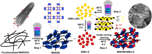
For the synthesis of this nanocomposite, 0.1 g of MWCNT/HKUST-1 (MW/HK) was dispersed in distilled water (40 mL), and then, synthesized NiMn-S was added under vigorous stirring. The reaction time was 6 h and the temperature was maintained at 40°C. The product was isolated, rinsed several times with H2O, and centrifuged at 5000 rpm for 5 min (three times); three steps as shown in Scheme 1 were followed. The MW/HK/NiMn-S product was obtained as a porous dark solid (0.17 g). Also, the color changes for all samples over different synthesis steps are shown in Figure S17.
2.5 Electrochemical studies
Infrared spectrometer (IR) correction was also considered in all calculations.
2.6 Turnover frequency (TOF) calculation
In this equation, J in mA cm−2 is the current density at defined overpotential, n is the total number of moles of metal ions of catalysts on the electrode, F is equal to ∼96485 C mol−1 and corresponds to the Faraday constant, while A is the geometric area of the electrode (cm2).
2.7 Computational study
3 RESULTS AND DISCUSSION
3.1 Preparation and analysis of nanocomposites
The MWCNTs/HKUST-1/sulfidized-NiMn-LDH nanocomposite (for simplicity, further abbreviated as MW/HK/NiMn-S) was synthesized through three consecutive steps as shown in Scheme 1. In Step 1, the primary MWCNTs/HKUST-1 (further abbreviated as MW/HK) nanocomposite was prepared by a hydrothermal method using a copper precursor, 1,3,5-benzenetricarboxylic acid, and functionalized MWCNTs. Then, in Step 2, the MWCNTs/HKUST-1/NiMn-LDH (further abbreviated as MW/HK/NiMn) nanocomposite was obtained by a simple process using nickel and manganese salt precursors and the MW/HK synthesized in Step 1. In the last Step 3, the hydrothermal sulfidation of MW/HK/NiMn was performed, resulting in the final MW/HK/NiMn-S nanocomposite.
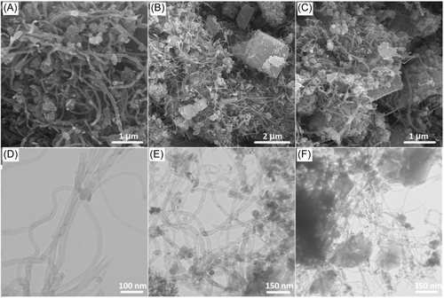
The morphology of different samples in each synthesis step was examined by field emission scanning electron microscopy (FE-SEM) analysis. The FE-SEM images of CNTs (Figure S1A) clearly show an almost uniform morphology and size and also no agglomeration after their functionalization. Therefore, LDH and MOF introduced during the next synthesis steps can penetrate these nanoparticles and maintain the uniformity of the synthesized composite samples. Figure S1B,C shows NiMn-LDH and its sulfidized NiMn-S derivative, respectively. These images were obtained to investigate whether the sulfidation of the final composite changes the morphology of NiMn-LDH. In fact, it is evident that the morphology of LDH after the sulfidation shows less agglomeration, while small nanosheets of different sizes have been formed. Because of this effect, small nanosheets can easily be located between MWCNTs. The FE-SEM image in Figure 1A shows the MW/NiMn composite, and it can be seen that small LDH nanosheets are well dispersed between the nanorods. This can improve the electrochemical performance, and effective interaction between the two materials contributes to a synergic effect. The FE-SEM image of MW/HK (Figure S1D) shows that the functionalized MWCNTs completely surround HK, with a cubic morphology. This further confirms the effective interaction between these two materials, forming a MWCNTs/NiMn-LDH (MW/NiMn) nanocomposite. The FE-SEM images in Figure 1B,C for MW/HK/NiMn-S nanocomposite are presented in two different resolutions, showing that the cube-like HK is completely surrounded by MWCNTs, while small NiMn-LDH nanosheets are located on the surface of nanocomposite as well as between the nanorods; there is also an effective interaction between these three materials in the final nanocomposite. The transmission electron microscopy (TEM) images are shown in Figure 1D–F. Figure 1F indicates that the functionalized MWCNTs have high purity and are free of any other substances. Figure 1E reveals that small LDH nanosheets are homogeneously and uniformly located between the MWCNTs. Finally, Figure 1F demonstrates that when HK is added to the nanocomposite, all three components in the final product have adequate interaction with each other. These results are in agreement with the FE-SEM analysis. The elemental content in the final nanocomposite (Table S1) was determined by elemental CHNS analyses and inductively coupled plasma (ICP) atomic emission spectroscopy.
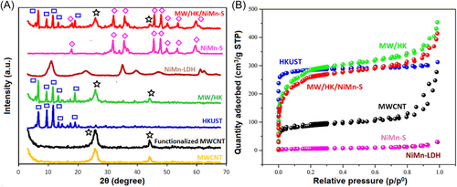
Powder X-ray diffraction (PXRD) analysis was used to confirm the phase purity and monitor structural features in the obtained samples (Figure 2A). Initially, the diffraction patterns of MWCNTs before and after the functionalization were compared, indicating that there is no change in diffraction peaks after the treatment. The characteristic peak for this group of materials is observed at 2θ of 26.52° in both samples, although the intensity slightly increased after functionalization. This is likely associated with the looseness of CNTs after treatment with acid,88 forming well-ordered MWCNTs. It has already been confirmed that MWCNTs show two diffraction peaks at 2θ of 26.52° and 44.36°, corresponding to (004) and (102) planes, respectively.89 The HK diffraction pattern demonstrates the high crystallinity and superior purity of the MWCNTs, since there are no additional peaks.90 With the formation of the MW/HK composite, the diffraction patterns of both materials showed no change in the number of diffraction peaks. The only difference was a slightly lowered peak intensity of MW, while the existence of nanoparticles did not cause structural changes in HK. The diffraction peaks of pure LDH refer to a series of peaks indexed with particular planes that are in agreement with the literature, indicating successful synthesis of this material.91 NiMn-LDH shows LDH diffraction peaks at 2θ of 11.38°, 22.94°, 35.63°, 39.57°, and 47.02°, which are associated with (003), (006), (009), (012), and (110) planes, respectively, which is in an agreement with the reported values.92 The intensity of the NiMn-LDH diffraction pattern is lower than that of HK, which may be due to the presence of anions in LDH or its large interlayer spacing. After sulfidation of the resulting sample, a mixture of three components was obtained: Mn3O4 with a tetragonal structure (JCPDS Card No. 024-0734), NiS with a rhombohedral structure (JCPDS Card No. 012-0041), and NiS with a hexagonal structure (JCPDS Card No. 02-1280).76, 93, 94 The final nanocomposite (MW/HK/NiMn-S) reveals no changes in the diffraction pattern after the addition of HK and MWCNT to NiMn-S, except for the presence of signals characteristic for these materials. Thus, MW/HK/NiMn-S has a combination of all three materials (MWCNTs, HKUST-1, and NiMn-S), while NiMn-LDH reveals phase changes only after sulfidation step, in agreement with previous results.76
Fourier-transform infrared spectroscopy (FT-IR) analysis was used to further investigate the prepared materials (Figure S2). The presence of functional groups can be monitored by comparing the spectra of MWCNTs before and after the functionalization. MWCNTs are composed of highly symmetric carbon atoms with slightly different states of charge, leading to the creation of a small electric dipole, which leads to the emergence of a C═C band at 1634 cm−1 that is not observed in the parent sample before treatment with acids.95 Furthermore, the bands at 1747, 900–1200, and 1369 cm−1 are attributed to the ν(C═O) of carbonyl groups, ν(C–O) of carboxylate or alcohol functionalities, and O–H bending band of –COOH, respectively.96 The bands at 1423 and 1608 cm−1 are due to vs and vas of COO stretching vibrations. The bands at 2927, 2876, and 2969 cm−1 are also ascribed to ν(CH) vibrations of methylene groups produced at the defect sites of functionalized MWCNT surface with acid, while the ν(OH) band at 3452 cm−1 further confirms the presence of OH groups.97, 98 The latter act as potential active sites for binding to other materials and also enhance the dispersion of MWCNTs in aqueous solutions. For HK, the broad ν(OH) band at 3410 cm−1 corresponds to H2O ligands. The bands at 1634 and 1428 cm−1 are due to ν(COO) vibrations of 1,3,5-benzenetricarboxylate ligands.99 The band at 1108 cm−1 corresponds to a C–O–Cu vibration.100 The FT-IR spectrum of MW/HK evidently demonstrates the peaks related to both samples. The band at 3428 cm−1 in the NiMn-LDH spectrum can be ascribed to the tensile vibration of OH groups (Ni-OH and Mn-OH) and interlayer water molecules. There is also a δ(H2O) band at 1634 cm−1. Characteristic peaks of interlayer NO3− and CO32− are seen at 1385 cm−1. The broad peaks around 700 cm−1 are related to tensile M–O–M, O–M–O, and M–O (M = Ni, Mn) vibration modes; these are caused by the metal cation lattice vibrations.101 For NiMn-S, the band at 1384 cm−1 becomes less intense, whereas a new peak evolves at 1102 cm−1; it is characteristic of the bending vibrations of the sulfide groups.102 After sulfidation, the bands of metal cation tensile vibrations also shift (652 → 582 cm−1 and 557 → 513 cm−1). This could be linked to the replacement of oxygen atoms (O) with sulfur atoms (S), resulting in a less robust bond between the metal and sulfur in comparison to the bond between the metal and oxygen. Consequently, the FT-IR data demonstrate that NiMn-LDH was also partially vulcanized, which is in agreement with other analyses. The FT-IR spectrum of the final MW/HK/NiMn-S nanocomposite features bands that are almost identical to those of the composite components; however, there is a small displacement due to the interaction of components.
For the different materials obtained, the surface areas were evaluated by measuring the N2 adsorption and desorption isotherms (Figure 2B). For the functionalized MWCNTs, it is obvious that the adsorption and desorption curves represent a type II isotherm and a 324 m2 g−1 surface area. A hysteresis loop can be observed in this isotherm at pressures above 0.4, which is caused by the mesoporous structure and capillary condensation.103 The HK sample features a type I isotherm with a 1119 m2 g−1 surface area. Compared to HK, the MW/HK material has a slightly decreased 995 m2 g−1 surface area, while the size and volume of pores are larger. This is probably due to the presence of MWCNTs, which aid in the removal of nonreactive copper species that have blocked the HK pores. In fact, Yang et al.104 found that the addition of MWCNTs increases the volume and size of the MOF-5 pores because of the removal of unreacted species during the composite synthesis process. As expected, NiMn-S has the lowest surface area among the studied materials. Nevertheless, the final MW/HK/NiMn-S nanocomposite has a large 908 m2 g−1 surface area that is comparable to those of HK and MW/HK. The textural properties of the synthesized samples are further summarized in Table S2.
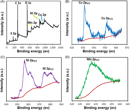
According to Figures 3 and S3, X-ray photoelectron spectroscopy (XPS) confirms the states of the surface electrons in the MW/HK/NiMn-S nanocomposite, while also investigating the elemental bonding properties. As shown by the full-scan XPS spectra (Figure 3A), C, O, S, Cu, Ni, and Mn are present. The main peak at 283.38 eV corresponding to C–C bonds was considered for the C 1s spectrum deconvolution (Figure S3A). A strong HK–composite interaction was supported by the negligible change in the O 1s binding energy values, from 535.8 to 531.58 eV, which was found for the composite surface oxygen atoms (Figure S3B).105-107 The composite remained as HK, as confirmed in Figure 3B, highlighting the characteristic XPS peaks of Cu(II) at 931.46 eV (Cu 2p3/2) and 951.88 eV (Cu 2p1/2).108 The Ni 2p high-resolution spectrum reveals two characteristic peaks with binding energies of 856.48 eV (3+) and 861.38 eV (2+), associated with Ni 2p3/2 (Figure 3C), while the peaks at ∼875.48 eV (3+) and ∼879.88 eV (2+) are attributed to Ni 2p1/2.109-111 The Mn 2p3/2 peak at 642.38 eV suggests the presence of Mn(IV) (Figure 3D).112 The high-spin state induces the presence of Mn(III) (d4) ions within NiMn-LDH, while hydroxyl ions act as weak field ligands. An unstable lattice in NiMn-LDH can result from the susceptibility of the high-spin d4 complexes to the Jahn−Teller effect. Hence, due to oxidation of Mn(III) into Mn(IV). The characteristic Mn(IV) peak can be observed within the Mn 2p3/2 XPS spectrum.113 The binding peaks at 168.28 and 161.58 eV result from the deconvolution of the S 2p spectrum, with the respective correspondence to O–S–O and C–S bonds (Figure S3C),114-116 suggesting that S was successfully introduced into the configuration, as a result of the reaction involving oxygen and functional groups that contain carbon with sodium sulfide nonahydrate.
3.2 Electrocatalytic studies
The HER performance of all the synthesized samples (including MW, HK, MW/HK, NiMn-S, MW/HK/NiMn, and MW/HK/NiMn-S) was investigated in a three-electrode cell using potassium hydroxide solution as an electrolyte (1 M). The results of LSV confirm the overpotential of the electrocatalysts and are shown in Figure 4A, including a Pt/C curve for comparison. The obtained results indicate that at a current density of 10 mA cm−2, the lowest overpotential (73 mV) is shown by the MW/HK/NiMn-S sample. Under similar conditions, the overpotentials for other samples are 153 mV (MW/HK/NiMn), 175 mV (MW/NiMn-S), 229 mV (NiMn-S), 286 mV (MW/HK), 308 mV (MW), and 331 mV (HK) (Figure 4B). The reasons for the superior performance of the MW/HK/NiMn-S electrocatalyst over other samples can be related to (i) the abundance of electroactive centers, that is, the simultaneous presence of Cu, Ni, and Mn metal centers in the structure, (ii) the improved conductivity due to the presence of sulfur, and (iii) the overall porosity and stability of the structure. The behavior of this electrocatalyst toward HER was also compared with that of recently reported HER electrocatalysts in a basic electrolyte medium (Table S3), indicating the superior characteristics of MW/HK/NiMn-S.
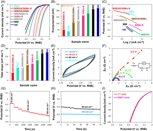
The CV curves of MW/HK/NiMn-S at different scan rates on a non-Faraday area show the electrochemical active surface area (ECSA) for the electrocatalyst (Figure 4E). EIS measurements were performed to understand the kinetic trends of electrocatalysis in HER. Nyquist plots of samples at a −0.4 V overpotential are shown in Figure S4. As shown in this figure, MW/HK/NiMn-S electrode has the lowest charge-transfer resistance between all samples, which indicates its better electrocatalytic activity compared to the other electrodes. Additionally, Nyquist plots of MW/HK/NiMn-S (Figure 4F) indicate that its resistance against the charge transfer is reduced by increasing the overpotential, which confirms the excellent performance of the electrocatalyst. Such a remarkable electrocatalytic behavior can be justified by the presence of electroactive metals (Ni, Cu, and Mn), sulfur centers, and the synergic effect between them. The synergistic effect refers to the behavior in which the interaction of chemical species or structures leads to an overall influence that surpasses the sum of the effect of each individual component. This effect is due to the combination of at least two materials, showing more important effects of each of them.121, 122 In the case of NiMn-S, the presence of active metals such as Ni and Mn with different oxidation states creates many active sites on the one hand and electron transfer and increases the conductivity due to the formation of Mn(IV) ↔ Mn(III) and Ni(II) ↔ Ni(III) states on the other hand. Regarding the good conductivity of S-containing compounds, the presence of Ni, Mn, and S in the LDH structure results in a synergistic effect that is far superior to the effect of each of these components. This synergistic effect improves the conductivity of LDH; higher conductivity also improves the electrocatalytic performance. Also, the unique structure of MW/HK/NiMn-S is attributed to a combination of MW nanosheets with the layered structure of LDH and the hexagonal plate-like HK structure. It is likely that the radius of the hydrogen bubbles produced during HER is reduced, allowing its facile release from the surface of the electrocatalysts and, thus, preventing the degradation of the electrode's surface. In the equivalent Randle circuit (inset of Figure 4F), Rs is the resistance of the solution, Rct is the charge-transfer resistance across the electrode/electrolyte interface, and Q1 corresponds to the constant phase element of the electrolyte/electrode interface. Hence, the Nyquist plot curves correspond to the charge transfer at the electrode/electrolyte interface. The Warburg element expressed by W characterizes the ion diffusion to the electrode with some porosity at the intermediate-frequency region; W thus reveals the frequency dependence on this diffusion. Another important parameter for the performance of electrocatalysts is their stability.123 To investigate this parameter, the MW/HK/NiMn-S electrocatalyst was studied by multi-step chronoamperometry. In the 10–100 mA cm−2 window of current densities, there are no significant changes in the potential along time at a fixed current density (Figure 4G). However, the potential changes rapidly on altering the current density, with a decreasing trend with increasing current densities. This result indicates a high charge transfer, superior conductivity, and excellent stability of the electrocatalyst.124 Also, after 72 h, no significant changes in the potential were observed at the 50 and 100 mA cm−2 current densities, thus confirming better stability of MW/HK/NiMn-S (Figure 4H). Electrocatalyst stability was further monitored by measuring CV curves. As shown in Figure 4I, negligible decay is observed after 6000 cycles, suggesting the excellent stability of MW/HK/NiMn-S electrocatalyst.
Similar to HER, the performances of the obtained electrocatalysts were studied for OER in a three-electrode system (Figure 5). The LSV results indicate that the MW/HK/NiMn-S nanocomposite shows an excellent performance at 10 mA cm−2 with a minimum overpotential (163 mV). It is significantly inferior to that (288 mV) of a commercially used IrO2 electrocatalyst (Figure 5A). Under similar conditions (10 mA cm−2), the overpotentials for other samples are 216 mV (MW/HK/NiMn), 300 mV (MW/NiMn-S), 316 mV (NiMn-S), 342 mV (MW/HK), 433 mV (MW), and 490 mV (HK) (Figure 5B). The overall performance of MW/HK/NiMn-S is remarkable compared to those of recently reported OER electrocatalysts in a basic electrolyte (Table S4). The excellent OER performance of MW/HK/NiMn-S can be due to its multistructural composition as described above.
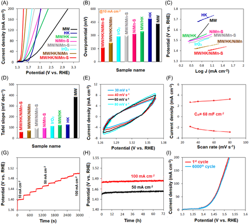
In the case of OER, Tafel plots were used to study the kinetic features (Figure 5C,D). According to the results, one of the lowest Tafel slopes, which demonstrates the best performances, is observed for the MW/HK/NiMn-S electrocatalyst (57 mV dec−1); this value is much lower than that of IrO2 (112 mV dec−1). Other tested electrocatalysts show higher values: 71 mV dec−1 (MW/HK/NiMn), 95 mV dec−1 (MW/NiMn-S), 96 mV dec−1 (NiMn-S), 123 mV dec−1 (MW/HK), 127 mV dec−1 (HK), and 384 mV dec−1 (MW). Another important parameter in electrocatalytic behavior concerns the existence of a high ECSA. Therefore, this parameter requires to be studied. It was confirmed that there is a direct relationship between ECSA and Cdl;125 that is, when an electrocatalyst has a high Cdl value, its ECSA will also be high and then, it is expected to show superior electrocatalytic performance. We performed the CV test in the range of non-Faraday potential with different rates of scans to study this important parameter. When CV curves are plotted, we can obtain lots of current density as a function of scan rate for the electrocatalysts. The slope of these graphs will be equal to Cdl of the electrocatalysts. Now, the electrocatalyst with the highest Cdl will have the largest ECSA and, therefore, can demonstrate the best electrocatalytic behavior. In this work, ECSA of electrocatalysts was studied to confirm the superior performance of MW/HK/NiMn-S toward OER (Figure 5E,F). The plots of current density as a function of scan rate were obtained at 1.31 V (vs. RHE) so that the line slope equals to Cdl. Among various catalysts (Figures 5E,F, S5, and S6), the highest value of Cdl is observed for the MW/HK/NiMn-S electrocatalyst (68 mF cm−2).
The stability of the MW/HK/NiMn-S electrocatalyst during the OER process was also evaluated using chronopotentiometry (Figure 5G,H). A multistep chronopotentiometry test (Figure 5G) confirmed the stability of the electrocatalyst. A rapid increase in the potential is observed on changing the density of current from 10 to 100 mA cm−2, indicating acceleration of the charge transfer. However, the potential remains constant at any fixed current density, thus proving the stability of the electrocatalyst. Also, the change of the potential at 50 and 100 mA cm−2 current densities was very small after 72 h, confirming the stability of the MW/HK/NiMn-S electrocatalyst (Figure 5H). Finally, for further assessment of MW/HK/NiMn-S electrocatalyst stability, CV curves were recorded. As shown in Figure 5I, there is no decay after 6000 cycles, which demonstrates the stability of the electrocatalyst.
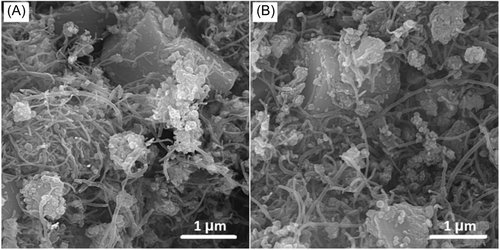
According to the obtained results, the presence of three different metal centers (Cu, Ni, and Mn) in a trimetallic electrocatalyst is crucial for such a remarkable performance of the MW/HK/NiMn-S nanocomposite. Previous studies showed that the Cu-based composites, when combined with metals such as Ni and Mn, become particularly effective in terms of bifunctional electrocatalytic activity. For example, Sirisomboonchai et al.126 synthesized CuOx nanowires@NiMnOx nanosheets for this purpose, revealing good HER/OER behavior as a bifunctional electrocatalyst. At 10 mA cm−2, the overpotential values were 390 mV (OER) and 80.7 mV (HER). The alteration of the oxidation states of these metals (formation of Mn3+ and Ni2+ during HER, and Mn4+ and Ni2+ during OER) and the instability of these states during HER and OER resulted in interesting catalytic behavior for water splitting.126 The introduction of the second and third metals into the electrocatalyst composition modifies their electronic structures and hydrogen adsorption-free energies, which might lead to very amazing catalytic behavior.127 Jia et al.113 also reported excellent performance in terms of OER, low overpotential, and optimal stability of the composite based on MWCNTs with bimetallic nanoplates. Moreover, homogeneous dispersion of metal nodes in the structure of MOF can lead to the formation of numerous electroactive sites accessible in the electrocatalyst.128, 129 The deposition of LDH and MOF as active materials on the surface of MWCNTs provides favorable chemical and electrical paths that accelerate electron transfer for efficient electrocatalytic behavior. The effective role of MWCNTs in this composite can be assigned to their structural flexibility, high surface area, and high conductivity, which can facilitate high carrier mobility in MW/HK/NiMn-S, hence increasing electron acceptance capacity and displacement. These advantages lead to the improvement of the electrocatalytic performance of MW/HK/NiMn-S. The other effect of the presence of MW in this composite involves the acceleration of charge transfer from active sites to the electrode surface, hence improving the electrocatalytic performance. Also, according to the XRD pattern of the MW/HK/NiMn-S nanocomposite (Figure S7), it is clear that it has good stability, based on the fact that after the electrocatalytic test, there is is no significant change in the composite structure. SEM results also revealed that the morphology of the nanocomposites did not change after HER and OER reactions; only a slight variation can be observed in the dispersion of different components (Figure 6). However, the interaction between these three components is well maintained. In addition, to study the stability of S in NiMn-S, we examined the XRD pattern of this material before and after HER and OER tests. As shown in the Figure S8, its stability was maintained. Additionally, after the electrocatalytic process, the content of S was determined by ICP analysis. It was observed that the content of S decreased from 13.67% to 11.46% and 12.18% for HER and OER, respectively. This can be due to the removal of S atoms on the surface of the electrocatalyst.
3.3 DFT calculations
The HER and OER electrocatalytic activities of MW/HK/NiMn-S catalysts were simulated using DFT calculations. Owing to the random distribution of functionalized MWCNTs, we considered NiMn LDH, NiMn-S LDH, and HK/NiMn-S LDH as models. The optimized structures of NiMn LDH, NiMn-S LDH, and HK/NiMn-S LDH are shown in Figures 7A, S9, S10, and S11, respectively. The Gibbs free energy for each elementary reaction step in HER and OER was determined (Figure 7B).
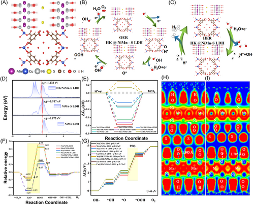
The hydrogen absorption energy change (∆GH*) of adsorbed H is treated as a key descriptor to evaluate the HER performance.130 The adsorption structures of H at Ni and Mn sites on NiMn LDH, H at Ni, Mn, and S sites on NiMn-S LDH, and Ni, Mn, Cu, and S sites on HK/NiMn-S LDH were modeled (Figure S12). Figure 7C shows the values of ∆GH* of adsorbed H at the Mn atom (−0.821 eV) and the Ni atom (−0.347 eV) in NiMn LDH. After doping by S, ∆GH* values of adsorbed H at the Ni site and the Mn site in NiMn-S LDH decrease to −0. 323 and −0.781 eV, respectively. On the contrary, H adsorption at the Ni site and the Mn site on HK/NiMn-S-LDH shows lower ∆GH* values of −0.235 and −0.647 eV, respectively. Compared to other sites adsorbed with H, the ∆GH* value of the Ni site on HK/NiMn-S LDH is almost close to 0 eV, indicating that the use of a multicomponent composite as an electrocatalyst leads to the appropriate H-binding energies, which can typically result in the enhanced HER performance.
Three main stages, H2O adsorption, H2O dissociation, and H2 evolution, are involved in the HER pathway in an alkaline medium. Figure 7D shows the following H2O adsorption energy changes (): −1.16 and −0.32 eV for Ni and Mn sites on NiMn LDH, respectively; −1.19, −0.37, and −0.55 eV for Ni, Mn, and S sites on NiMn-S LDH, respectively; and −1.21, −0.42, −0.49, −0.65 eV for Ni, Mn, Cu, and S sites on HK/NiMn-S LDH, respectively. The value of below zero promotes efficient adsorption of H2O for the next steps of H2 evolution. For the water dissociation process, H2O is favorably adsorbed at metal centers.131 At the same time, the OH bond cleavage permits H to bind to the closest oxygen site, and this process can facilitate the dissociation of adsorbed *H2O to yield OH* and H*. Lastly, a pair of H* radicals are combined to yield H2 via the Tafel reaction. The calculated energy barrier for H2O splitting on Ni sites of the HK/NiMn-S LDH catalyst is 1.68 eV. It is lower than those of other sites of NiMn LDH, NiMn-S LDH, and HK/NiMn-S LDH catalysts. In other words, the DFT calculations prove that the multicomponent design of HK/NiMn-S LDH reduces a barrier of energy necessary for the dissociation of H2O and accelerates the generation of hydrogen.
To explore the intrinsic mechanism and gain insights into why the multicomponent composite shows a superior HER performance, the d-band center of NiMn LDH, NiMn-S LDH, and HK/NiMn-S LDH was further calculated. The center of the d-band of Ni is decreased from −0.875 eV in NiMn LDH to −0.917 eV in NiMn-S LDH and −1.238 eV in HK/NiMn-S LDH, leading to decreased H-binding strength (Figure 7F).132 The obtained results indicate that the decrease of the center of d-band lowers the energy of H-adsorption and expedites H-desorption from the catalyst for the HER.
The water oxidation mechanism was also analyzed in an alkaline medium, involving four proton–electron transfer steps. The sites of Ni and Mn on NiMn LDH, the sites of Ni, Mn, and S on NiMn-S LDH, and the sites of Ni, Mn, and S on HK/NiMn-S LDH were selected as active sites for OER (Figure S13). The profile of Gibbs free energy is shown in Figures 7G and S14. The formation of O* from OH* represents the potential-determining steps (PDS) for Ni, Mn, and S sites for all of the NiMn LDH, NiMn-S LDH, and HK/NiMn-S LDH electrocatalysts. Compared to the overpotential values of S sites on NiMn-S (0.66 eV) and HK/NiMn-S (0.54 eV), the large Gibbs free energies of PDS (in case that U = 0 V) for Ni and Mn sites lead to lower O2 production and sluggish OER kinetics. The overpotentials of Mn/Ni sites on NiMn LDH, NiMn-S LDH, and HK/NiMn-S LDH catalysts are 0.83/0.81, 0.77/0.81, and 0.71/0.70 eV, respectively. In addition, the overpotential of the Cu site on the HK/NiMn-S LDH catalyst is 0.74 eV. Obviously, the overpotential of PDS for S sites on both NiMn-S LDH and HK/NiMn-S LDH catalysts is lower than those of Mn and Ni sites on NiMn LDH, NiMn-S LDH, and HK/NiMn-S LDH, thus improving the OER kinetics.
Oxygen desorption is one of the key steps in the OER process. A relatively large distance between the O–M bond is favorable for desorption of O2 from the substrate. As shown in Figure S15, the length of O2 absorbed in Ni sites on HK/NiMn-S LDH is 1.805 Å, which is longer than those of NiMn LDH (1.758 Å) and NiMn-S LDH (1.765 Å). On the other hand, the adsorption of O2 at Ni sites on HK/NiMn-S LDH is −2.64 eV, which is inferior to those of NiMn LDH (−2.72 eV) and NiMn-S LDH (−2.67 eV), indicating that O2 weakly interacts with the HK/NiMn-S LDH catalyst. The electron localization function (ELF) profile further confirms that the O2 absorbed on Ni sites of HK/NiMn-S LDH has a shorter O–Ni bond (Figures 7H-I and S16). Hence, the introduction of several components into pristine NiMn LDH and HK/NiMn-S LDH optimizes a thermodynamic energy barrier and facilitates the OER process. The theoretical analysis is well consistent with the experimental polarization curves (Figure 7). In summary, both experimental and theoretical simulation data demonstrate that the synergetic effects on multicomponent composites are beneficial to accelerate the reaction kinetics and thus promoting superior electrocatalytic performance of HK/NiMn-S LDH.
Hence, we can suggest that the remarkable performance of MWCNTs/HKUST-1/sulfidized NiMn-LDH as a bifunctional electrocatalyst toward HER/OER can be explained as follows: (1) The intrinsic properties of MWCNTs and the sulfidized composite facilitate ion transfer by forming a unique structure with proper electrical conductivity and stability; (2) The presence of NiMn-LDH and Cu-MOF that contain three different electroactive metal centers leads to a synergistic effect in the composite, facilitating electron and ion transfers and modifying the binding energy required for the electrochemical reactions owing to the defects created in the interface of heterostructures;133 (3) MWCNTs and MOFs have a high surface area, providing a vast active surface for electrocatalytic reactions and many channels for the transfer of mass. As a result, MWCNTs/HKUST-1/sulfidized NiMn-LDH contributes to a growing family of stable and efficient bifunctional electrocatalysts for HER/OER processes.
4 CONCLUSION
A new MWCNTs/Cu-MOF/sulfidized-NiMn-LDH (MW/HK/NiMn-S) nanocomposite was assembled, characterized, and applied as an exceptionally powerful dual-function electrocatalyst for the H2 and O2 evolution processes. This composite has proper conductivity due to sulfidation of NiMn-LDH as well as the presence of MWCNTs with superior conductivity that promotes carrier transport. Alternatively, the performance of this electrocatalyst toward HER and OER is enhanced owing to the presence of three different metal centers (Cu, Ni, and Mn) as electroactive sites. A remarkable catalytic behavior of MW/HK/NiMn-S in a 1 M KOH electrolyte solution can be explained by its increased surface area, improved electrical conductivity and, therefore, accelerated charge transfer, proper dispersion, and accessibility of electroactive sites. At a 10 mA cm−2 current density, this nanocomposite requires inferior overpotentials with smaller Tafel slopes for HER (73 mV and 75 mV dec−1) and OER (163 mV and 57 mV dec−1) compared with other common bifunctional catalysts, including those based on noble metals. For MW/HK/NiMn-S, TOFs at η = 10 mV are also more than threefold superior than that of IrO2 (OER) or close to that of Pt/C (HER). Experimental evidence and DFT studies demonstrated that the efficient electrocatalytic function is ascribed to (i) the multi-interface heterogeneous structure of the electrocatalyst that combines functionalized nanotubes (MWCNTs) with an abundant surface area of Cu-MOF and nanosheets of NiMn-S LDH, (ii) favorable branched morphology and the 3D hollow structure, which endow MW/HK/NiMn-S with accelerated reaction kinetics, a large number of active sites, and a reasonable adsorption energy toward the reactant. In addition, the excellent stability of this electrocatalyst was also observed during the OER and HER processes. The present multi-interface engineering approach opens up new perspectives for designing future dual-function electrocatalysts based on tri- or multimetallic composites with ideal conductivity, stability, and advanced water-splitting performance.
ACKNOWLEDGMENTS
This work was supported by the University of Maragheh, Iran. This work is based upon research funded by Iran National Science Foundation (INSF) under project No. 4025105. This work was financially supported by the Foundation of State Key Laboratory of High-efficiency Utilization of Coal and Green Chemical Engineering (Grant No. 2022-K31) and the Zhejiang Province Key Research and Development Project (2023 C01191). Alexander M. Kirillov acknowledges the Foundation for Science and Technology (LISBOA-01-0145-FEDER-029697, PTDC/QUIQIN/3898/2020, LA/P/0056/2020, UIDB/00100/2020).
CONFLICT OF INTEREST STATEMENT
The authors declare no conflicts of interest.


