Structure-guided discovery of cyclin-dependent kinase inhibitors
Abstract
CDK2 inhibitors containing the related bicyclic heterocycles pyrazolopyrimidines and imidazopyrazines were discovered through high-throughput screening. Crystal structures of inhibitors with these bicyclic cores and two more related ones show that all but one have a common binding mode featuring two hydrogen bonds (H-bonds) to the backbone of the kinase hinge region. Even though ab initio computations indicated that the imidazopyrazine core would bind more tightly to the hinge, pyrazolopyrimidines gain an advantage in potency through participation of N4 in an H-bond network involving two catalytic residues and bridging water molecules. Further insight into inhibitor/CDK2 interactions was gained from analysis of additional crystal structures. Significant gains in potency were obtained by optimizing the fit of hydrophobic substituents to the gatekeeper region of the ATP binding site. The most potent inhibitors have good selectivity. © 2007 Wiley Periodicals, Inc. Biopolymers 89: 372–379, 2008.
This article was originally published online as an accepted preprint. The “Published Online” date corresponds to the preprint version. You can request a copy of the preprint by emailing the Biopolymers editorial office at [email protected]
INTRODUCTION
Cyclin-dependent kinases (CDKs) are a family of 16 serine/threonine kinases that are key regulators of the mammalian cell cycle.1 Aberrant activity of CDKs is a hallmark of many human cancers.2 Inhibition of the essential, rate-limiting kinase activities of CDK2 and CDK1 can produce apoptosis in cancer cells, but only reversible cell cycle arrest in normal cells. Hence, CDK2/CDK1 inhibitors have potential as anticancer agents with a good therapeutic window.3, 4 In fact, several CDK inhibitors including flavopiridol,5 roscovitine,6 and BMS3870327 are being evaluated in clinical trials.
Early structural biology studies elucidated the dramatic conformational changes that activate CDK2 upon phosphorylation and complexation with cyclin E.8 Subsequent studies have brought the total of CDK2 3D-structures in the protein databank9 (PDB) to 135 as of July 2007. Of these, 80 are binary CDK2/ligand complexes, 14 binary CDK2/cyclin complexes, and 40 ternary CDK2/cyclin/ligand complexes. These structures have demonstrated that while activation gives large structural changes involving the catalytic residues near the ATP-γ-phosphate, there are only subtle changes in the adenine subsite. Consequently, the binding interactions of inhibitors in this subsite can be well characterized in the technically less-challenging binary complexes; these offer the added advantage of diffracting to higher resolution than the ternary complexes.
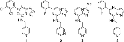
Recently, our laboratories have described the discovery of a novel series of CDK inhibitors as well as initial structure/activity explorations.10, 11 Herein, the structural chemistry of these inhibitors is traced beginning with hits identified via high-throughput screening. Three-dimensional structures and inhibition potency will be compared for alternative templates and substituents that gave rise to inhibitors potent against CDK2 and CDK1, but selective versus most other kinases.
RESULTS AND DISCUSSION
Initial Hits
High-throughput screening using a CDK2/cyclin A activity assay yielded inhibitors 1 and 2 as hits with IC50s of 500 and 800 nM, respectively (Table I). These two inhibitors both have 5,6-bicyclic heterocyclic cores with 5-halophenyl and 7-pyridinylmethylamino substituents (numbered as shown for 1), but differ in the placement of the nitrogens in the core to give either the pyrazolopyrimidine 1 or imidazopyrazine (IP) 2. Crystals of 1 complexed with CDK2 diffracted to 1.5 Å and refined with good statistics (Table II). The crystal structure shows the well-established bilobed consensus kinase structure, with the inhibitor bound in the adenine binding pocket. The N-terminal lobe is composed of a β-sheet and helix C (Figure 1, top), and the C-terminal lobe is largely α-helical (Figure 1, bottom). The hinge region connects thetwo lobes; the inhibitor is bound in a deep cavity at theinterface between the lobes (Figures 1 and 2). The backbone hinge connecting the two lobes exposes Glu81CO, Leu83NH, and Leu83CO as a triad of H-bonding groups. The inhibitor makes H-bonds to two of these groups Leu83NH···N1 and Leu83CO···HN (at the 7-position). The short Glu81CO···C2 distance of 3.0 Å also indicates a favorable interaction that could be considered a CH···O H-bond. At the back N4-Lys33NH -Asp145 COO− forms bridged H-bonds. Inhibitor 1 has the same binding mode as previously reported inhibitors with the same pyrazolopyrimidine (PP) core12 [1Y91] or the similar purine core in olomucine13 [1W0X] and roscovitine14 [2A4L].
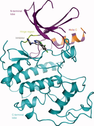
Ribbon diagram depicting the crystal structure of the 1/CDK2 complex. The N-lobe is colored purple, helix C purple and orange, the C-lobe cyan, and the hinge green. In this and subsequent figures consistent atom colors are used: oxygens-red, nitrogens-blue, halogens-green, sulfurs-yellow, carbons colored by region: inhibitor-grey, N-lobe-purple, hinge-green, C-lobe-cyan. The 5-dichlorophenyl group has two conformations with the chlorines either up or down.
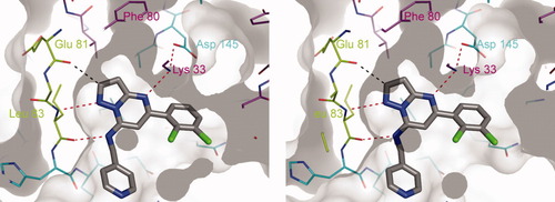
Stereoscopic view of a close-up of the binding site in the 1/CDK2 structure looking into the open front of the binding cavity. The inhibitor is shown as thick sticks colored as in Figure 1. H-bonds are shown as dotted lines to the labeled residues. Only one of the two phenyl ring conformations is shown.
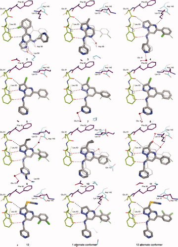
Crystal structures of CDK2 complexes of inhibitors 1–5, 7–12. Interacting residues are shown including the hinge Phe80:Leu83, catalytic residues Lys33, Asp145, and additional residues with direct contacts or water bridges to the inhibitors. The structure of 1 is included for reference in all of the panels as narrow sticks, but is not visible when it exactly overlaps the other inhibitor. Alternative conformations of the 5-dichlorophenyl group were included for 1 and 12.
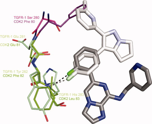
Comparison of the 2/CDK2 structure with that of a fluorophenyl-containing inhibitor complexed with TGFβR1TK [1RW8]. The hinge backbones were overlapped. Carbon atom colors for the TGFβR1TK complex: inhibitor-white, N-lobe-pink, hinge-light green.
| Inhibitor | IC50 (nM) |
|---|---|
| 1 | 500 |
| 2 | 800 |
| 3 | 20,000 |
| 4 | 1000 |
| 5 | 10 |
| 6 | 300 |
| 7 | 100 |
| 8 | 100 |
| 9 | 10 |
| 10 | 70 |
| 11 | 600 |
| 12 | 900 |
| No.a PDB Entry | Resolutionb (Å) | Completenessb (%) | Rsymb,c (%) | 〈I/σI〉d | rms Deviations | Ramachadran Distributione (%) | Rwork (%) | Rfree (%) | |
|---|---|---|---|---|---|---|---|---|---|
| Bond Length (Å) | Bond Angle (°) | ||||||||
| 1; 2R3F | 1.50 (1.51–1.50) | 88. (49.) | 6.0 (18.3) | 11.2 (2.4) | 0.015 | 1.3 | 89.7/9.9/0.4/0 | 20.4 | 23.6 |
| 2; 2R3G | 1.55 (1.56–1.55) | 99. (100) | 4.3 (51.2) | 31.4 (2.9) | 0.015 | 1.4 | 90.1/9.5/0.4/0 | 18.2 | 21.1 |
| 3; 2R3H | 1.50 (1.51–1.50) | 98. (56.) | 4.7 (34.0) | 25.5 (3.0) | 0.014 | 1.3 | 92.5/7.1/0.4/0 | 19.5 | 21.9 |
| 4; 2R3I | 1.28 (1.29–1.28) | 96. (89.) | 4.3 (39.3) | 25.4 (2.2) | 0.017 | 1.5 | 90.9/8.7/0.4/0 | 17.8 | 20.3 |
| 5; 2R3J | 1.65 (1.66–1.65) | 81. (58.) | 7.9 (46.2) | 8.7 (1.9) | 0.012 | 1.2 | 89.3/10.2/0.4/0 | 19.8 | 23.6 |
| 7; 2R3K | 1.70 (1.71–1.70) | 96. (82.) | 5.0 (44.0) | 24.3 (1.8) | 0.013 | 1.2 | 91.8/7.8/0.4/0 | 18.8 | 23.2 |
| 8; 2R3L | 1.55 (1.66–1.65) | 93. (61.) | 4.5 (31.9) | 24.6 (2.0) | 0.014 | 1.3 | 90.4/8.8/0.8/0 | 19.4 | 22.6 |
| 9; 2R3M | 1.70 (1.71–1.70) | 96. (95.) | 3.7 (58.4) | 28.6 (2.5) | 0.012 | 1.2 | 91.8/7.8/0.4/0 | 18.5 | 21.6 |
| 10; 2R3N | 1.65 (1.66–1.65) | 93. (81.) | 3.7 (47.4) | 28.0 (2.1) | 0.016 | 1.5 | 90.8/8.3/0.8/0 | 19.2 | 23.5 |
| 11; 2R3O | 1.80 (1.82–1.80) | 99. (98.) | 4.6 (50.4) | 25.5 (3.2) | 0.013 | 1.3 | 90.5/9.1/0.4/0 | 18.7 | 22.7 |
| 12; 2R3P | 1.65 (1.66–1.65) | 85. (73.) | 3.2 (47.7) | 26.1 (2.2) | 0.013 | 1.3 | 93.3/6.3/0.4/0 | 18.1 | 22.3 |
- Space group: P212121; a = 53.3 ± 0.4 Å; b = 71.4 ± 1.2 Å; c = 72.0 ± 0.3 Å.
- a Compound number as in Table I.
- b The number between parenthesis is for the last resolution shell.
- c R sym = Σ|I - 〈I〉|/ΣI, where I = observed intensity, 〈I〉 = average over Friedel and symmetry equivalents.
- d Represents an average of the ratio of the intensity over the evaluated error on intensity measurement.
- e Ratio of nonglycine:nonproline residues that fall within one of the following regions of the Ramachandran plot: most favored, additional allowed, generously allowed and disallowed, as output by the program PROCHECK. There are ∼250 nonglycine:nonproline residues in a structure.
Alternative Cores
Adding a 3-Br substituent to inhibitors similar to the initial hits gave up to a 50-fold increase in potency. This increase arises from filling the hydrophobic cavity at the back of the binding site. The cavity is delimited by Val18, Ala31, Val64, the gatekeeper Phe80, Leu134, and Ala144. The 3-bromo-PP 5 has an IC50 of 10 nM. Other 3-Br, 5-phenyl inhibitors with similar 7-substituents, but different bicyclic cores are 10- to 30-fold less potent (6–8, Table I). The precise overlap of 5, 7, and 8 with 1 is apparent from their crystal structures (Figure 3). While the structure of the 6/CDK2 complex was not determined, its binding mode was inferred to be similar to other IPs such as 3. Since the inhibitors 5–8 share the same binding mode, their different potencies must arise from different electronic interactions within the common geometrical framework. One possible difference is the strength of H-bonding to the hinge backbone. Interaction energies were computed by ab initio methods for simplified models with 7-NH2 groups and various 3- and 5-substituents. Similar results were obtained for the models with bare (3-H,5-H), monosubstituted (3-H,5-Ph), or disubstituted (3-Br,5-Ph) cores, indicating that the electron withdrawing nature of the 3-Br and 5-phenyl substituents has little effect on the strength of H-bonding to the hinge. However, the interaction energy of the core IP (as in 6) was computed to be ∼1.5 kcal/mol more favorable (10-fold lower IC50) than for the other three cores (Table III). H-bonding is less favored in the pyrazole-containing cores (5, 7), since the adjacent nitrogen atom reduces the electron density on the acceptor N1. The prediction that IPs (6) have stronger hinge binding coupled with the experimental observation that the PPs (5) are more potent indicates that other factors make overriding contributions to potency. The dominant factor seems to be interactions with N4 of the PPs, either directly with the amino group of Lys33 or with a water-bridged network.

| 3,5 Groups | IP | IPy | PP | PPy |
|---|---|---|---|---|
| 3-H,5-H | −7.8 | −6.8 | −6.7 | −5.6 |
| 3-H,5-Ph | −7.8 | −6.7 | −6.5 | −6.0 |
| 3-Br,5-Ph | −7.6 | −6.6 | −6.3 | −5.9 |
| 3-H,5-H + water | −15.2 | −11.8 | −15.2 | −10.9 |
- IP, imidazopyrazine; IPy, imidazopyridine; PP, pyrazolopyrimidine; PPy, pyrazolopyridine.
SAR at the 3-Position
The cavity occupied by the 3-substituent is relatively small and bounded at the back by the large gatekeeper Phe80. This part of the protein structure is also quite rigid as evidenced by its lack of variability in complexes with inhibitors of divergent chemotypes and in the conversion from inactive CDK2/inhibitor binary complexes to active CDK2/cyclin A-or-E/inhibitor ternary complexes. The cavity is well suited to small hydrophobic substituents as evidenced by the high potency of 5 (Br) and 9 (ethyl). However, small changes in size 10 (cyclopropyl), polarity 11 (methanol), or both 12 (SCN) give substantial reductions in inhibitory potency. The 3D-structures of 5, 9, and 12 in the binding site show that they precisely overlap the reference structure of 1. The bicyclic core in structures of 10 and 11 is displaced from that of reference 1. For 10, the steric bulk of the 3-cyclopropyl substituent may cause it to shift away from Phe80. The unusual H-bond network involving the 3-CH2OH of 11, two water molecules, Lys33NH , and Asp145NH may contribute to its shift.

SAR at the 5-Position
The inhibitors presented here generally have a 5-phenyl or a 5-halophenyl group. The 2,3-dichloro-phenyl group of 1 shows two orientations in the binding site with the chlorine atoms either up or down (Figure 3, 1 alternate conformer). The dual conformations indicate that a group as large as 2,3,5,6-tetrachloro-phenyl could be bound at this position. The SAR at the 5-position will be further discussed in subsequent publications.
CONCLUSIONS
High-resolution structures (1.3-1.8 Å) were determined for CDK2 complexed with each of 11 inhibitors and refined with good statistics. These structures revealed that inhibitors with four related bicyclic cores share a common binding mode stabilized by two H-bonds to the hinge within the ATP site. The PPs derive superior potency via an H-bond network involving N4, catalytic residues, and water molecules. Optimizing the fit of a small hydrophobic 3-substituent to the binding pocket was a key for potent inhibitors. The best inhibitors (5 and 9) are equipotent against the closely related CDK1 and CDK2 (100% identical in the ATP site, 64% overall), but show selectivity against less-related kinases: 20-fold selective against CDK4 (72% ATP site, 42% overall) and 50- to 100- fold against ERK2 (64% ATP site, 34% overall).
METHODS
Protein Purification
CDK2 was expressed in Sf9 insect cells using a recombinant baculovirus encoding human CDK2 and was purified following slight modifications to the published method.1 Briefly, Sf9 cells adapted to serum-free medium (Invitrogen) were maintained in shake flasks at 27°C. Cells (2.0 × 10⁶) were infected with human CDK2 baculovirus at a multiplicity of infection of 10. At 72-h post infection, the cells were harvested and lysed in lysis buffer (10 mM Tris-HCl, pH 7.5, 25 mM NaCl, 1 mM ethylenediamine tetraacetic acid (EDTA), 2 mM Tris(2-carboxyethyl)-phosphine hydrochloride (TCEP), 1 ml/l of protease inhibitor cocktail III [EMD Biosciences]). After microfluidizing, the lysate was clarified by ultracentrifugation (100,000g for 1 h at 4°C) and loaded onto a 20-ml DEAE-Sepharose Fast Flow HiPrep column (GE Healthcare) pre-equilibrated in lysis buffer. The NaCl concentration of the flow-through was adjusted to 50 mM prior to loading onto a 25-ml SP-Sepharose column (GE Healthcare). CDK2 eluted in the flow-through and was further purified using an ATP-agarose column (Sigma) pre-equilibrated in 10 mM Na-4-(2-hydroxyethyl)-1-piperazineethanesulfonic acid (HEPES), pH 7.5, 25 mM NaCl, 1 mM EDTA, and 2 mM TCEP. CDK2 was eluted with 150 mM NaCl in the presence of 10% glycerol. Peak fractions were pooled based on SDS-PAGE and concentrated to 20 mg/ml. The concentration of CDK2 was determined using 6M GndHCl by UV spectrophotometry and an extinction coefficient at 280 nm of 35,680 M−1/cm. Mass spectrometry confirmed that the mass of CDK2 was 33,975 Da, consistent with N-terminus acetylation (expected mass without acetylation is 33,930 Da and 33,972 Da for the acetylated protein). The acetyl group is visible in the electronic density of the ordered N-terminus tail of the protein and is included in the crystal structures.
CDK2-Cyclin E Kinase Assay
Details of the assay can be found in Ref.10. The IC50s are estimated to be accurate within a factor of 3.
Crystallization
Crystallization used an optimized version of the published protocol. A first set of crystals was grown by mixing 2 μl protein with 2 μl of the following precipitant: 50 mM Na-HEPES, pH 7.4, 100 mM ammonium acetate, 8% v/v polyethylene glycol (PEG) 4000, and 1 mM TCEP. These crystals were used to generate a microseeds stock as follows: the crystals were crushed in 1 ml of stabilizing solution (50 mM Na-Hepes, pH 7.4, 100 mM ammonium acetate, 12% v/v PEG 4000, and 1 mM TCEP). This sample was then sonicated for 2 min. Crystals used for soaking were obtained by mixing 2 μl of protein, 2 μl of precipitant at 12% v/v PEG 4000, and 0.2 μl of diluted seed stock. The optimum dilution ratio for the seed stock that would yield a few crystals per drop has to be determined empirically by using serial dilutions, but was quite constant for a given stock. The seeds can be kept at 4°C for several months. All crystal growths were performed at 18°C. Microseeding yields larger crystals with lesser mosaicity. The crystals grow in the same space group, with similar cell dimensions, as the original CDK2 structure.
Preparation of Cocrystals for Data Collection
The crystals were transferred to a soaking solution which was 50 mM Na-Hepes, pH 7.4, 50 mM ammonium acetate, 8% v/v PEG 4000, 4% v/v glycerol, 1 mM TCEP. The compound was added from a 100 mM solution in 100% DMSO to a final concentration of 1 mM, 1% v/v DMSO. Actual inhibitor concentration may be less due to compound solubility. The soak duration was at least 7 days. The crystals were then harvested in a microloop, swept quickly through a cryosolution containing 50 mM Na-HEPES, pH 7.4, and 29% v/v Glycerol, and flash-frozen in liquid nitrogen.
Data Collection and Processing, Structure Determination, and Refinement
The X-ray diffraction data were collected either on a Rigaku-MSC R-Axis IV with a H2R X-ray generated equipped with Osmic mirrors, or at the Advanced Photon Source (APS, Argonne, IL) at the IMCA (Industrial Macromolecular Consortium) 17-ID or 17-BM beam lines on either a ADSC Q210 (17-ID) or Mar165 (17-BM) CCD detector. Raw data when available may be requested directly from TOF. Images were processed and merged with the program HKL2000.16 Conversion from intensities to amplitudes was calculated with the software TRUNCATE.17 All refinements were performed using the program BUSTER.18 A 1.50-Å resolution structure of PDB entry [1E1X]19 was used for the initial model for refinement. The figures were made using the PYMOL20 software.
Computational Methods
Calculations were performed using the version 7.0 of the Jaguar program.21 Geometry optimizations were carried out using the LACVP** pseudopotential22 used for bromine substituted compounds and the 6-31G** basis set used on all other atoms.
 ()
()The geometries used for the interaction energy calculations were obtained after preprocessing the X-ray structures. Those compounds for which no X-ray structural information was available were manually docked to mimic the closest X-ray structure analog. The hinge region was isolated and further reduced from the carbonyl of Glu81 to the amino group of Leu83 for carrying out free energy calculations. The phenylalanine side chain was mutated to glycine, and both ends were capped with a methyl.
The geometries used for the free energy calculation involving more than two species were obtained after preprocessing with QM-MM calculations of the complexes CDK2-inhibitor. For computations of optimum geometry in the CDK2 active site, the frozen orbital-based QM-MM method, QSite,34, 35 developed by Schrödinger was used. The QM region included residues from the amide carbonyl of Glu81 to the amine of Leu83, including the complete residue Phe82, and the side chains of Lys33 and Asp145. Each inhibitor was also a part of the QM region, along with two waters bridging to Lys33 and Asp145. The QM method used was B3LYP/6-31G* for all atoms in the QM region. All coordinates in the QM region were free to adjust during the optimization. The remaining residues in a 9.0-Å sphere around the binding site comprised the minimized MM region. All coordinates were frozen beyond the binding site sphere, and form part of the MM region.
A reduced version of each ligand was used for the calculations. The 7- position was kept as a free amine. 3-H, 5-H; 3-H, 5-Ph and 3-Br,5-Ph substituted PPs, IPs, PPys, and IPys were considered.


