Combined use of drones and geophysics in enhancing cemetery studies: Two case studies in Northern Ireland, UK
Abstract
The real-time use of drone-derived orthoimagery and ground-penetrating radar (GPR) facilitate conjunctive ground surveying and aerial visual reference of subterranean features within cemeteries. Geospatially referenced visual outputs allow sympathetic restoration and assist in understanding historical use. Two contrasting case studies demonstrate this: The first is a subterranean wall, built to separate Catholic and Protestant burials in a civic cemetery. The second example is the accurate positioning of unmarked inhumations in an Irish Famine burial ground, which facilitated preservation as a memorial garden in a hospital complex.
1 INTRODUCTION
The obvious use for cemeteries maybe augmented by their presence as green spaces, refugia for wildlife (Lynch, 2019) and sites of cultural/historical importance: We consider the latter in this work. The predominantly subterranean nature of cemetery features indicates that publicly accessible geophysical results and interpretations may enhance engagement in the history of these sites by illustrating features that cannot be seen from the surface (Nobes, 2022). Such data can be best conveyed by referencing underground features with the use of visually appealing, accurate geophysics combined with drone-acquired aerial imagery.
Cemeteries, especially graveyards, are sites of continual human activity over long periods of time. In addition, they are often left unaffected by redevelopment, making such places unique in the archaeological/historical landscape. This contradiction (activity vs. preservation) creates a location where subsurface features maybe preserved and not just burial sites. Here, we document how conjunctive remote sensing and geophysics were used in assessment of a cemetery and a burial site. This allowed sympathetic enhancement and preservation of both sites, requested by the managing authorities for each. These are selective and in no way comprehensive representations of how our combined approach using real-time drone-based and geophysical (in this case, GPR) surveying may be used to highlight the methods and in one case show the presence of features not associated with burial practice.
We follow Sprague's (2005) definition of a cemetery as a generic burial location that may or may not have a religious basis whilst graveyards are associated with religious belief and thus usually with an associated building (church, mosque, temple, synagogue). Pardoe (1988) considers the two terms as equivalent. Rugg (2000) sets out clearly her criteria in defining a cemetery: (1) locational access (frequently on the margins of towns/cities); (2) an obvious perimeter with wall or hedge; (3) internal access routes (paths and roads to grave markers); and (4) internal layout (surface and subsurface). For our case studies that have no extant or previous religious building associated, we use the term ‘cemetery’ where no specific religious affinity occurs. We use ‘graveyard’ where a religious authority has control. Importantly for this work, Sprague (2005) considers the geography and subsurface nature of cemeteries throughout the world, and comments on the variety of buried features that may be present, along with individual human internments. These include sink holes, mass graves, underground water sources, pipelines, tunnels (especially cists, souterrains, passage tombs). Some of these maybe related to former funerary practices, for instance, sinkholes—which Bement (1994) describes as places bodies may have been placed, or simply thrown in. Similarly, souterrains (underground passages), burial mounds and raths may have their origin prior to establishment of a church graveyard or cemetery yet are often associated with such (Bailey & Roycroft, 2003).
2 METHODS
The abundance of metal and close proximity of headstones, mausolea, hard surfaces and access routes in cemeteries/graveyards make application of some geophysical techniques (magnetometry and resistivity) problematic. The use of ground-penetrating radar (GPR) in detection of organic remains, air voids and disturbed ground overcomes some of these limitations, along with manoeuvrability and a balance of three-dimensional (3D) and two-dimensional (2D) imagery where access allows. Electromagnetic surveys were used to augment GPR in Case Study 2. Accurate location can be equally challenging, with ornamental and self-seeded trees often abundant—sometimes precluding good differential GPS measurement. Combining GPR surveys with autonomous drone flight imagery allows ground surveys to be referenced visually with aerial imagery, creating a relative positional accuracy without the need for a total station. Such a combined GPR/drone-based survey has the advantage of creating real-time orthophotography, topographic maps and vegetation health indices, such as Visible Atmospherically Resistant Index (VARI) or Normalized Difference Vegetation Index (NDVI). Such processed drone imagery can not only serve as a positional reference but show ground disturbances such as burials not visible to the naked eye at ground level (Rocke & Ruffell, 2022) and only visible on GPR; thus, one technique allows verification of the other. Finally, the outputs are easily understandable for all, in our case studies allowing presentation at a visitor's centre (cemetery Case Study 1) and preservation of the site during redevelopment of a hospital (graveyard Case Study 2).
3 CASE STUDY 1: BURIED WALL, BELFAST CITY CEMETERY, FALLS ROAD, BELFAST, NORTHERN IRELAND
3.1 Background
Opened in 1869 as a cross-denominational burial ground in West Belfast (Figure 1), the issues of Catholic and Protestant traditions (along with Jewish and other religious affinities) soon had to be reconciled. This was reached by Belfast Corporation and the Catholic Bishop of Down and Connor, Dr Patrick Dorrian, agreeing on separate areas of burial grounds and cemetery entrances for Catholics and Established Church (mainly Protestants and Dissenters; Hartley, 2014).
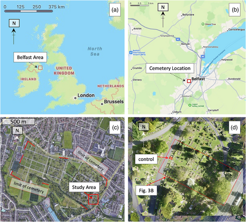
The acreage allotted to Catholics was ‘separated from the other sections of the Cemetery by a sunken wall’ (Hartley, 2014, p. 8). This buried wall has no surface expression, yet is well known locally, with the same brick-lined 2 × 2 m section excavated (‘control’ marked on Figure 1d) and exposed for visitors on European Heritage Open Days tours (https://www.europeanheritagedays.com/) and Dark Tourism visits or performances such as described by Dowler (2013) who comments that ‘tours often point out the place where a below-ground brick wall was designed to divide the Protestant and Catholic plots’ (p. 793). Local accounts expand on Bishop Dorrian's wishes for the buried wall, to prevent Protestant and Catholics fraternizing in the afterlife. Strangely, Hartley's (2014) map of the cemetery has no location for the wall, yet the same map, displayed on a visitor's board at the cemetery itself, does have a rough location. For such an unusual feature, redolent of the sectarianism that was rife in Ireland and Northern Ireland through its history, civic authorities commissioned the authors to map the extent and nature of the wall, which we did using a conjunctive drone and geophysical (GPR) survey. When requested by the managing authorities to determine the extent of the underground wall, we considered a range of approaches. These included excavation, which is not feasible in a cemetery, magnetometry (such a location will have abundant discarded metal) and resistivity—which has the best potential for subsurface imaging (Hansen et al., 2014) but would have been problematic on tarmac roads, concrete/gravel paths, between/over and around irregularly spaced grave plots and mausolea.
3.2 GPR
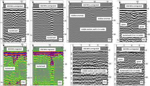
We used a GuidelineGeo (Mala Geosciences) high dynamic range GPR system with 450- and 160-MHz shielded antennas: Both have in-built GPS with differential correction. The 450 MHz is a smaller unit, more suited to manoeuvring between the non-uniform distributions of headstones, grave plots and mausolea, which also restricts 3D surveys throughout much of the mapped area. 2D data (Figure 2) were gathered perpendicular to the presumed orientation of the buried wall, using the periodically excavated location as a control, extending north and south, until no similar anomaly was visible. Where unequivocal, the central points, or shallowest hyperbola thought to be the wall, were marked with white flags as control points. One 8 × 8 m area (Figure 3) was apparently free of interference from surface and subsurface objects, allowing a 3D survey in this location. We outlined this area with measuring tape on all four sides (outlined in Figure 3) and marked corners with flags, then flew the site with the drone before the GPR survey commenced.

3.3 Drone imagery
Belfast City Cemetery is not only a place of rest for the deceased, and thus for family and friends to visit in peace, but is adjacent to Falls Park and serves as an extension of green space in an urban location. The southern end of the buried wall was found to be only 25 m from the Falls Road, an arterial route for Belfast. For both reasons, the quietest drone with best quality camera combination had to be used; hence, we deployed a DJI Mavic Air on an autonomous flight over the outlined site, acquiring 455 individual images, augmented by oblique drone photographs where necessary. These were combined and processed using DroneDeploy™ (under licence) to create an orthomosaic with the outlined GPR survey serving as ground control points. The orthophotography was processed for topography and vegetative indices, also using DroneDeploy™, but its primary use here was to geolocate the GPR survey and provide a visual reference for the public: No topographic or vegetative imprint from the subterranean wall was evident in the drone data.
3.4 Results
The 450- and 160-MHz antennas showed consistent results in terms of the northern and southern limits of the buried wall, being 2 m wide in the central portion, tapering out at each end. Strong hyperbolas on unmigrated profiles likely relate to the mix of brick and air voids in sandy soil, providing a significant contrast in dielectric permittivity. Fewer 160-MHz (a larger antenna) profiles could be acquired, due to the density and layout of grave plots, headstones, trees, etc., but Line 3 (Figure 3: in open ground) shows how this antenna imaged the flat-top to the wall more successfully than the 450-MHz unit. The same applies to 3D surveys, with such irregular layout to the graves hampering grid layout: The one 3D survey conducted (see above) does show the capability of such an approach. For this small (8 × 8 m) area, we used the time slice function built into the GuideLine Geo GX Ground Explorer to process the data in a 3D volume, time sliced here at 80 cm depth using a zero angle, aperture of 5 and threshold of 27: this simplifies the output into binary colours of red (positive amplitudes) and blue-green (negative amplitudes).
Future GPR studies of such vertical structures would benefit from delineation with a multiplexer antenna array, although the same issues of manoeuvrability in such confined areas remains. Colour outputs from 2D GPR data can obscure reflections but are useful in determining relative radar wave amplitudes (Kadioğlu & Daniels, 2008). An additional advantage for this kind of study is the outputs from this work form part of a public visitor's centre in the cemetery, and reactions from non-specialists were that the use of colour were easier to visualize for those without colour blindness. A similar comment can be made for integrating drone imagery with the GPR trace of the buried wall (Figure 3), wherein the process of successively surveying the feature at right angles, plotting the GPR location and then recording this in an autonomous drone flight is both a recommended scientific approach, but also builds an accessible visual narrative. The intention of a 3D survey (Figure 3C) was to improve visualization, but its limited extent (due to the cemetery layout) was not as successful as anticipated. Nonetheless, in a more orderly cemetery with less trees and mausolea, combining drone data with 3D geophysical plots would provide better, integrated outputs.
4 CASE STUDY 2: IRISH FAMINE ‘POOR GROUND’, TYRONE AND FERMANAGH HOSPITAL, OMAGH (COUNTY TYRONE), NORTHERN IRELAND
4.1 Background
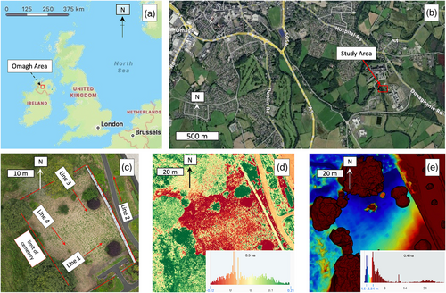
This site is located south-east of Omagh Town, County Tyrone (Northern Ireland: Figure 4) was surveyed when development of a nearby children's playground revealed three unmarked burials. An historical desktop study had not been undertaken, and an Ordnance Survey map from 1905 indicated a ‘burial ground’ at this location. For the site described here, such a proper background check (in 2007) was made, where the same term ‘burial ground’ was located. The area was being redeveloped to create a modern, regional hospital, and the plan was to build a respite home here for elderly patients. The hospital authorities expected a similar number of burials to the one above, so were dismayed when a 2007 GPR survey (described by Ruffell et al., 2009) revealed over 200 burials, as well as a large pit, possibly a mass grave, as well as a linear radar anomaly (discussed below). The costs of excavation, disinterment and reinternment for one individual are significant: For hundreds, this would be financially prohibitive. The resolution was to preserve the site as a memorial garden and build around, instead of on top of the graves.
4.2 GPR and drone survey methods
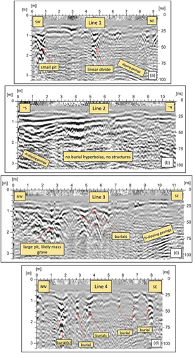
For this study, we revisited the memorial garden site, now within the modern hospital. The sensitive nature of the site precluded a full, repeat GPR survey, so we reprocessed the selected original data (Mala Geosciences 100-, 200- and 400-MHz unshielded antennas) in MalaVision™ (Figure 5) to compare improved outputs with drone-derived imagery.
The site is close to an air ambulance landing pad, thus only a small drone (DJI Mavic Mini Pro 2) without autonomous flight capability was used at low altitude, and 150 images were manually captured—enough for the creation of an orthomosaic and topographic analysis.
4.3 Results
Given that this is a known location of unmarked burials, it acts as a control on what remotely sensed and geophysical imagery will show, the main issue being false positives from unknown utilities and subsurface collapses. In this case, the digital terrain model derived from drone data shows numerous depressions consistent with burials (Figure 4), while VARI does not show any anomalies in burials of this age (Rocke & Ruffell, 2022). The multi-proxy approach of (i1) ground depressions from drone imagery, (2) subsurface collapse from GPR and (3) bright GPR hyperbolas with multiples (‘ringing’) beneath gives reassurance that interpreting these as human burials is accurate (Figure 5).
4.4 Discussion
The Irish Famine cemetery can be divided into two areas: The southwest has approximately four times the number of burials than the northeast (Figure 6). A linear radar anomaly separates these areas, the nature of which is unknown, and is possibly complicated in parts by burials being coincident. A number of theories maybe advocated for this bipartite distribution: (1) Distribution reflects the process or sequence of burials, which maybe began somewhere in the south western section, and as the famine progressed, expanded north eastwards. (2) The south western and western area has thicker, more diggable ground, however, geology dips to the north, with lower ground and the Camowen River to the west, which is only a little supportive of this idea. Plus, a large pit suggestive of a mass grave occurs in the north-eastern section, amongst fewer burials, but is simply a vacant ground, regardless of diggability. (3) The two areas may reflect a religious divide, with the more numerous, poverty-stricken Catholic population dying in greater numbers and thus buried in the southwestern section. The solution is likely a combination of the three hypotheses, outlined below.
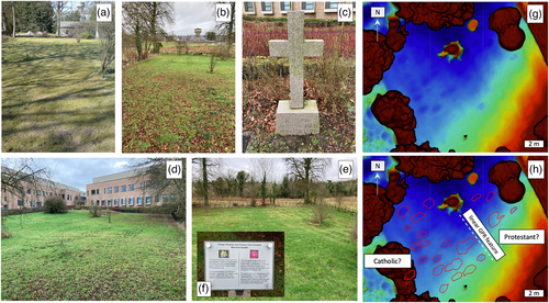
First, a mortuary at the time (mid-1800s) was to the north of the graveyard; thus, in accordance with the idea of minimum effort expended, the northern areas would be used for burials first. Second, the northern and western areas are likely to have thicker deposits of drift, including alluvium, as suggested by the topography of the area, proximity to the river and radar data. Third, considering the background to this work and the evidence from Case Study 1 (the buried wall), a divide between Catholic and Protestant burials is not unreasonable. This third hypothesis is supported by the observation in Ruffell et al. (2009) that assumed burials in the southwestern section had a preponderance of metal indications from EM surveys at the approximate torso region of burials, especially in the northern section. These were interpreted as grave goods—likely a crucifix on any coffin or shroud and/or rosary bead chains. However, two questions remain: Why is the supposed mass grave where it is, and why are these unmarked burials so clear on drone topography and GPR data? The supposed mass grave location may relate to hypotheses 1 and 2 (above)—the management of the site (this area remained with fewer burials) and diggability (the northern area may have thicker, diggable soils and drift geology). The remaining ground depressions have been left undisturbed since famine times (1840s), and the radar response may be caused by lime added to graves to suppress disease and odour (Geber, 2011). Over time, in the damp climate, this lime will calcify and possibly form a carapace over the decaying remains, creating an air-filled void and thus high-amplitude radar return.
5 CONCLUSIONS
Aside from grave markers (headstones, mausolea, grave plots), historical information is understandably buried and out of sight in cemeteries. The conjunctive use of current technology such as drone imagery and modern or reprocessed geophysics (here, GPR) provides geospatial and visual outputs that partially reflect this hidden history. In Case Study 1, the buried wall is occasionally and partly excavated for visitor events such as European Heritage Open Days: Our visual outputs augment this, with complete extent of the wall, the nature of which is now in a new visitor's centre at Belfast Civic Cemetery. The known extent and makeup of the wall may be useful to know in case of any future works (road improvement, further burials, mausolea repair). In Case Study 2, what could have been a financial problem for building works has, through survey of the subsurface, resulted in creation of a small sanctuary that memorializes victims of the Irish Famine. We expect the methods used here to be refined and maybe used in similar surveys elsewhere to record and possibly preserve the hidden history of cemeteries.
ACKNOWLEDGEMENTS
Case Study 1 was instigated by Ashleigh Kirkpatrick, kindly facilitated and approved through Anthony Rogan and Donald Bell (all of Belfast City Council) in development of the Visitor's Centre at Belfast City Cemetery. Initial surveys in Case Study 1 were conducted by AR with Roisin O'Reilly and Deidre Drain (Queen's University, Belfast). Case Study 2 was facilitated through Alan McCabe of Scadin Surveys Ltd and funded by Western Healthcare & Social Care Trust (Contract OD171). GPR equipment was kindly loaned by Mike Langton (GuidelineGeo/Mala Geoscience). Two anonymous reviewers provided invaluable comments, along with Editor Professor Grigorios Tsokas.
CONFLICT OF INTEREST STATEMENT
The authors claim no perceived conflict of interest.
Open Research
DATA AVAILABILITY STATEMENT
All drone and geophysical data as original format(s) are (will be) available at www.goqub.ac.uk/GIS/11016, under terms and conditions.


