Preserving Mesoporosity in Type III Porous Liquids through Dual-layer Surface Weaving
Graphical Abstract
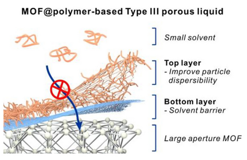
This work reported a dual-layer surface weaving strategy on metal–organic frameworks (MOFs) to realize Type III porous liquids (PLs) with apertures larger than the solvent molecules. The 1st polymer layer, cross-linked poly (t-butyl methacrylate), serves as a physical barrier to block the solvent molecules from entering the MOF pore. The 2nd layer uses a solvent-compatible polymer to reduce PL viscosity. As a result, a PL bearing a 3.1 nm aperture was successfully constructed.
Abstract
The fundamental limitation for pore preservation in a Type III porous liquid (T3PL) is the need for a small aperture from the porous filler to realize size exclusion of a bulky solvent. We present a dual-layer surface weaving strategy that can disregard this limitation and achieve micro- and mesoporous metal–organic framework (MOF)-based T3PLs even with apertures much larger than the solvent molecules. By first weaving a tight network of poly(tert-butyl methacrylate) on the MOF surface, the poly(dimethylsiloxane) (PDMS) solvent can be effectively excluded from the pores while smaller guest molecules such as CO2, C2H4, and H2O can freely access the interior, as confirmed by low-pressure adsorption isotherms. Further application of a PDMS-containing polymer coating helps lower the viscosity of the PL due to increased particle dispersibility. This strategy has resulted in the successful construction of T3PLs with aperture sizes up to 3.1 nm.
Introduction
Sorbent materials can be classified into two large categories, liquid sorbents and solid sorbents, according to their physical state.1 Liquid sorbents such as alkyl amine, ionic liquids, and poly(ethylene glycol) etc. are widely used for carbon capture and acid gas scrubbing etc.2-5 Benefiting from their fluidity, liquid sorbents feature high processability and have the ability to rapidly disperse heat. Nevertheless, due to the lack of intrinsic permanent porosity, their uses are limited to only a handful of applications. On the contrary, solid sorbents such as porous carbon, zeolites, silica gel, metal–organic frameworks (MOFs), covalent-organic frameworks (COFs), porous organic cages (POCs), and porous organic polymers (POPs) offer versatile solutions for gas separation, gas storage, catalysis, and environmental remediation etc. owing to their tailorable permanent porosity.6-17 However, their rigidity and powdery nature present challenges in materials’ processing and handling.
Porous liquids (PLs) have recently emerged as a unique class of sorbent materials that simultaneously feature liquid like fluidity and solid like permanent porosity.18-21 For instance, by creating a colloidal suspension of a crystalline porous material in a bulky solvent, the characteristic sorption properties of the solid sorbent can be harvested in liquid form. This type of PLs is classified as Type III PLs (T3PLs).22-30 The wide selections of porous particles bestow T3PLs with unique sorption characteristics beyond what is possible from conventional liquids.
The central challenge in the design of T3PLs is to prevent the occupation of permanent pores by solvent molecules. Therefore, a combination of a porous filler and a bulky solvent larger than its aperture size (a.k.a. window size) is necessary21 to prevent the solvent from infiltrating the pores. However, due to the size restriction of solvent molecules, this requirement greatly limited the preservable pore size in T3PLs. In fact, most of the reported T3PLs are microporous.22-30 Recently, our group designed and constructed a macroporous T3PL by dispersing a single crystalline hollow UiO-66-NH2 into a poly(dimethylsiloxane) (PDMS) solvent.31 The 0.4 nm aperture size on the defect-free UiO-66-NH2 shell could effectively prevent PDMS from entering the hollow MOF thereby preserving the macroporous cavity within. However, this strategy is not applicable to mesoporous MOFs because they are almost always accompanied by large apertures. Therefore, to further extend the library of T3PLs, there is a need to develop a universal strategy to create T3PLs that contains molecularly defined mesoporosity.
This work demonstrates a generalized approach to preserve permanent porosity in T3PLs when the MOF aperture is larger than the solvent molecule. This is realized by weaving a dual-layer dense polymer network on the MOF (Scheme 1). The first polymer layer is a cross-linked poly (tert-butyl methylacrylate) (xPtBMA) obtained through a non-covalent-based surface initiated-atom transfer radical polymerization (SI-ATRP).32 This high glass transition temperature (Tg) polymer functions as a barrier to prevent PDMS from accessing the pores. The second layer is a methacrylate polymer with PDMS pendant groups grown off from the first layer which can help improve the MOF particle dispersibility in the PDMS solvent. We demonstrate that the characteristic low-pressure CO2, C2H4, and water vapor sorption properties of both micro- and mesoporous MOFs can be well retained in their corresponding T3PLs using PDMS4k (Mn=4 kDa) as the solvent. Strikingly, by using this strategy, mesoporous PLs with aperture size as large as 3.1 nm can be obtained.

Schematic illustration of the dual-layer surface weaving process for the construction of T3PLs.
Results and Discussion
In our previous work, it was demonstrated that PDMS4k could gradually diffuse into UiO-66 through its 0.6 nm aperture over the course of 15 months leading to a 40 % reduction of PL porosity.25 Therefore, we started by selecting UiO-66 as the first example to validate the effectiveness of the dual-polymer coating as a size exclusion barrier. According to the previously reported method, monodispersed UiO-66 particles with an average size of 203 nm were synthesized.25 To apply a barrier layer on UiO-66, a methacrylate-based random copolymer (RCP) was first physically adsorbed to the MOF surface in dichloromethane (DCM) through inter-chain hydrogen-bond cross-linking.32 Subsequent SI-ATRP was carried out under the presence of tert-butyl methacrylate (tBMA) and 1,4-butanediol dimethacrylate (BDDMA, crosslinker) to produce UiO-66@xPtBMA. Then, monomethacrylate terminated PDMS and BDDMA were added to the sample to initiate a second SI-ATRP reaction to give UiO-66@xPtBMA@xPDMS (UiO-66@2 L, 2 L represents two layers). The transmission electron microscopy (TEM) image of UiO-66@xPtBMA shows a uniform ~22 nm xPtBMA layer on each MOF particle. After applying the second polymer coating, the polymer shell thickness increased to ~34 nm (Figure 1A and 1B). Although the phase boundary between the two polymer layers is invisible under TEM, the increase in coating thickness is a strong indication of the successful application of the xPDMS coating.
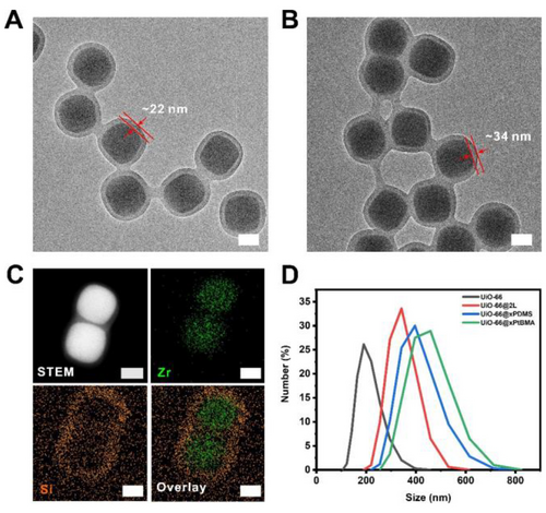
TEM images of (A) UiO-66@xPtBMA and (B) UiO-66@2 L. (C) STEM and EDS mapping images of UiO-66@2 L. Scale bars: 100 nm. (D) hydrodynamic particle sizes of UiO-66 dispersed in MeOH, UiO-66@xPtBMA, UiO-66@xPDMS, and UiO-66@2 L dispersed in DCM.
To further prove the dual-polymer coating structure, energy-dispersive X-ray spectroscopy (EDS) was used to map out the Zr and Si spatial distribution in UiO-66@2 L particles. It is apparent that Si signal mainly distributed at the edge of the particles suggesting the presence of xPDMS coating on the surface. Zr signal, on the other hand, located within the boundary of Si signal revealing a clear core–shell architecture (Figure 1C and S1). The average hydrodynamic particle size of the as-synthesized UiO-66 dispersed in methanol was ~190 nm as determined by the dynamic light scattering (DLS) data (Figure 1D). With the xPtBMA coating, the hydrodynamic particle size of the MOF particles increased to ~459 nm (in DCM). This drastic increase of particle size under DLS indicates particle aggregation which is likely due to poor swelling of xPtBMA in DCM. In contrast, UiO-66@2 L exhibited an average hydrodynamic size of ~342 nm despite bearing a thicker layer of polymer (Figure 1D). This demonstrates the effectiveness of the PDMS layer at improving the particle dispersity in an organic solvent. Finally, by comparing the powder X-ray diffraction patterns (PXRD), it is evident that the polymerization processes have no negative impact on the crystallinity and phase purity of the MOF (Figure S2A).
Next, we investigated how the polymer coatings impact the retention of MOF porosity in T3PLs using CO2 as the molecular probe. As a benchmark, the pristine UiO-66 adsorbed 56.9 cc/g CO2 (1 bar, 298 K) (Figure 2A). With the addition of a xPtBMA coating, the total normalized (to the MOF weight, based on the TGA data in Figure S3A) CO2 uptake capacity increased to 62.8 cc/g, slightly higher than that of the pristine UiO-66. This increment is likely due to the contribution of CO2 dissolution in the polymer shell. In fact, after digesting the MOF, the neat xPtBMA capsule could indeed dissolve 4.5 cc/g CO2 which satisfactorily accounted for this discrepancy (Figure S4A). With the dual-polymer coating applied, the normalized CO2 uptake capacity reduced to 47.9 cc/g. Blending UiO-66 with PDMS4k at a 1 : 3 mass ratio afforded a simple physical mixture denoted as UiO-66-PDMS4k. Blending UiO-66@xPtBMA, UiO-66@2 L and UiO-66@xPDMS with PDMS4k at a 1 : 3 mass ratio afforded three PLs: PL1, PL2, and PL3, respectively. The abbreviations of the PLs presented in this work are listed in Table S1. Similarly, CO2 adsorption isotherms were also collected for the PLs. For ease of comparison, the weight of PDMS4k was not accounted in the calculation of the CO2 uptake capacity. All PL isotherms were again normalized to the MOF weight. By comparing Figure 2A and 2B, it is clear that the isotherms of the PLs are similar to their solid counterparts. This suggests the successful retention of MOF porosity in their PL forms. However, minor discrepancies should also be noted. The normalized CO2 uptake capacity of UiO-66-PDMS4k is 12.3 % lower than that of UiO-66, likely due to partial infiltration of PDMS4k into UiO-66 pores.25 Surprisingly, the CO2 capacity of PL1 and PL2 are 13.2 % and 24.8 % higher than their solid counterparts, respectively. This positive deviation was contributed by the dissolution of CO2 in the PDMS solvent (1.6 cc/g at 1 bar, Figure S4B).
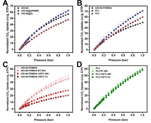
Normalized CO2 sorption isotherms at 298 K of (A) UiO-66 and its composite particles; (B) liquid samples; (C) UiO-66-PDMS4k after different treatment processes, and (D) PL2 after different treatment processes.
It is interesting that after resting UiO-66-PDMS4k at room temperature for 48 h, the normalized CO2 uptake capacity at 1 bar decreased from 49.9 to 45.5 cc/g (Figure 2C). Although the solvent infiltration process was slow, it is nonnegligible. To speed up the infiltration process, UiO-66-PDMS4k was heated to 100 °C for extended period of time. After another 48 hours and 7 days, the normalized CO2 uptake capacity decreased sharply to 28.0 and 20.6 cc/g, respectively. Compared to the freshly prepared UiO-66-PDMS4k, 58.8 % of the CO2 uptake capacity was lost at the end. In stark contrast, PL2 maintained its CO2 isotherms throughout the same treatment process, showcasing the effectiveness of the polymer barrier at preventing the infiltration of PDMS4k into UiO-66 (Figure 2D). As control experiments, the xPDMS coating alone was not able to inhibit the diffusion of PDMS4k likely due to the swelling of xPDMS by the chemically identical solvent. The xPtBMA coating, on the other hand, was proven to be effective at preventing porosity loss of UiO-66 suggesting that it is in fact responsible for the solvent barrier effect (Figure S5).
Rheological experiments were performed to examine the rheological properties of the T3PLs. The shear strain versus modulus plots of T3PLs containing UiO-66@2 L and various amount of solvent suggest that liquid-like behavior occurred above 10–20 % shear strain as indicated by the higher loss modulus than the storage modulus (Figure S6). Under the same shear rate of 100 s−1, increasing solvent percentage led to a decrease of PL shear viscosity, despite the surface coating. Interestingly, at a 3 : 1 solvent to filler mass ratio, the PL prepared using UiO-66@2 L exhibited a shear viscosity of 383 mPa ⋅ S which is appreciably lower than that of the PL prepared using UiO-66@xPtBMA (570 mPa ⋅ S) (Figure S7). This result demonstrates the effectiveness of the xPDMS coating on reducing the viscosity of the T3PLs. With the increase of solvent, the contribution of the xPDMS coating on lowering the viscosity of the PL gradually diminished due to the lowering of the interfacial concentration.
With the success built upon a microporous MOF, we proceeded to investigate a mesoporous MOF, MIL-101(Cr). MIL-101(Cr) possesses two spherical cages with inner diameters of ~2.9 nm and ~3.4 nm, respectively. It features a large aperture of 1.6 nm and a small one of 1.2 nm33(Figure 3A). Following the reported method, MIL-101(Cr) particles with an average diameter of 392 nm were synthesized (Figure S2B and S8 A). Through the same synthetic procedures, three new MOF@polymer composites, MIL-101@xPDMS, MIL-101@xPtBMA, and MIL-101@xPtBMA@xPDMS (MIL-101@2 L), were obtained (Figure 3B, S8 and S9). Water vapor sorption experiments at 298 K were used to investigate the pore retention of the PLs because of the unique two-step uptake profile of the pristine MIL-101(Cr). These two steps correspond to the pore filling of two distinct cages in the MOF.34 Similar to UiO-66 composites, MIL-101@xPDMS, MIL-101@xPtBMA, and MIL-101@2 L exhibited similar water sorption isotherm profiles to that of MIL-101(Cr) but with the 42 %, 32 %, and 33 % decrease of uptake capacity at 90 % relative humidity (RH), respectively (Figure S10). Mixing MIL-101@xPtBMA, MIL-101@2 L, and MIL-101@xPDMS with PDMS4k at a 1 : 5 mass ratio yielded three new PLs: PL4, PL5, and PL6, respectively. As a control sample, the physical mixture of MIL-101(Cr) and PDMS4k (1 : 5), denoted as MIL-101-PDMS4k, was also prepared. MIL-101-PDMS4k exhibited no substantial water uptake until P/P0=0.8. This is because PDMS4k can easily diffuse through the 1.6 nm apertures of MIL-101(Cr) and partially occupy its pores which has been demonstrated in our previous work.25 The infiltrated PDMS increased the hydrophobicity of the pores. Therefore, the water vapor condensation was delayed to a higher RH. The total water uptake was 0.1 g/g which is only a small fraction of the uptake capacity of the pristine MIL-101(Cr). In stark contrast, the normalized water uptake isotherms and the total uptake capacity of both PL4 and PL5 are identical to their solid counterparts (Figure 3C). All isotherms were normalized to their MOF weight based on the TGA data (Figure S3B). It is also worth noting that the isotherm of PL6 resembles that of MIL-101-PDMS4k with a water condensation pressure above 80 % RH despite a much higher total uptake capacity. This is an indication that the xPDMS layer is not an effective barrier to prevent solvent infiltration in T3PLs.
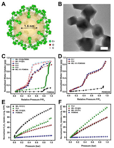
(A) The crystal structure of the largest cage in MIL-101(Cr). (B) TEM image of MIL-101@2 L. Scale bar: 200 nm. Normalized water vapor sorption isotherms at 298 K of (C) MIL-101(Cr) solid composite particles and liquids with a filler:solvent ratio of 1 : 5. (D) MIL-101(Cr)-containing liquids with PDMS550 as the solvent. Normalized (E) C2H4 and (F) CO2 sorption isotherms of MIL-101(Cr), MIL-101(Cr)@2 L, PL5, and PDMS4k at 298 K. All isotherms were normalized to their MOF weight.
To further test the capability of the xPtBMA layer at excluding solvent molecules, the PDMS4k solvent used in MIL-101-PDMS4k, PL4, and PL5 was replaced by a much smaller solvent molecule, PDMS550 (Mn=550 Da) to yield MIL-101-PDMS550, PL7,and PL8, respectively (Figure 3D). The molecular dynamics simulations revealed that PDMS550 has a radius of gyration (Rg) of 5.40 Å, compared to 13.76 Å for PDMS4k (Table S2). Despite the use of a much smaller solvent, PL7–8 still exhibited similar normalized water vapor adsorption isotherm and total uptake capacity to its solid counterparts.
In addition to water vapor, two more molecular probes, C2H4 and CO2, were used to investigate the pores in PL5, MIL-101(Cr), and MIL-101(Cr)@2 L. As shown in Figure 3E, The C2H4 uptake capacities of the pristine MIL-101(Cr) and PDMS4k were 115 cc/g and 8.4 cc/g, respectively. The normalized C2H4 uptake capacity of MIL-101(Cr)@2 L was 48.9 cc/g which is less than half that of the pristine MIL-101(Cr). This is likely due to partial occupation of the MOF pores by the monomers during the surface polymerization process. This observation is consistent with the water vapor uptake experiment. PL5, on the other hand, adsorbed 76.2 cc/g of C2H4 (normalized value) which confirms that PL5 remains porous. The reason why PL5 adsorbed more C2H4 than MIL-101(Cr)@2 L is because of the additional contribution of C2H4 dissolved in the excess PDMS4k solvent.
The CO2 adsorption of MIL-101(Cr)@2 L was less affected by the infiltration of monomers as it exhibited the same normalized uptake capacity of 39 cc/g at 1 bar as that of the pristine MIL-101(Cr)(Figure 3F). In contrast, only 1.6 cc CO2 was dissolved in each gram of PDMS4k under the same condition. It is well-known that the decrease of pore size in a MOF may positively contribute to the total CO2 adsorption due to increased interaction.35, 36 PL5, again, exhibited a higher normalized CO2 uptake capacity of 58 cc/g. These results further underpinned the conclusion that the dual-layer polymer coating can effectively preserve the pores of MIL-101(Cr) in PLs.
Encouraged by the success so far, we extended this dual-layer coating approach to another mesoporous MOF, NU-1000. This is a hexagonal MOF featuring one dimensional pore channels with an surprisingly large aperture size of 3.1 nm (Figure 4A).37, 38 This pore opening area is ca. 5 times that of the largest opening in MIL-101(Cr). Following the reported method, uniform NU-1000 particles were synthesized. NU-1000@xPtBMA and NU-1000@xPtBMA@xPDMS (NU-1000@2 L) were then prepared through the same SI-ATRP approach (Figure 4B and S11). The crystallinity of NU-1000 and the presence of the polymer coatings were confirmed by PXRD and EDS experiments (Figure S2C and S12). The MOF loadings in NU-1000@xPtBMA and NU-1000@2 L were calculated to be 39.3 % and 38.0 %, respectively, based on the TGA data (Figure S3C).

(A) Structure of NU-1000 with 3.1 nm aperture. (B) TEM image of NU-1000@2 L. Scale bar: 200 nm. (C) Normalized water vapor sorption isotherms at 298 K of NU-1000 solid composite particles and liquids with a filler:solvent ratio of 1 : 5. All isotherms were normalized to their MOF weight.
The water vapor isotherm of NU-1000 manifested a steep rise at 0.65 P/P0 which corresponds to the characteristic capillary condensation process of water vapor in the mesopores of NU-1000.39 The total water uptake was 0.97 g/g at 98 % RH at 298 K (Figure S13). The normalized water uptake capacities of NU-1000@xPtBMA and NU-1000@2 L decreased to 0.86 g/g and 0.80 g/g at 98 %RH, respectively (Figure 4C). Similar to MIL-101(Cr), a second capillary condensation process of water vapor in the polymer coated NU-1000 samples occurred at 90 % RH. This is likely due to monomer infiltration in the pores of NU-1000 during polymerization which led to a more hydrophobic pore environment. However, an appreciable amount of the mesopores was preserved as suggested by the similar isotherm in the range below 90 % RH as compared to that of the pristine NU-1000. Two T3PLs, PL9 and PL10, were prepared by mixing NU-1000@xPtBMA or NU-1000@2 L with PDMS4k at a mass ratio of 1 : 5. The normalized water uptake capacities were found to be 0.45 and 0.48 g/g for PL9 and PL10. The decreased water uptake capacity is likely due to two reasons: 1) partly occupation of solvent molecules in the mesopore due to imperfection in the polymer coating, and 2) pore shrinkage of NU-1000 as a result of contractive capillary force in multiple water vapor isotherm tests.40 Nevertheless, the capillary condensation phenomenon of water was also observed, although not as pronounced as the pristine MOF. It is, however, sufficient to prove that the mesopores of NU-1000 were at least partially preserved. In stark contrast, the physical mixture of NU-1000 and PDMS4k exhibited a linear adsorption isotherm with only 0.10 g/g water uptake capacity near saturation.
Conclusion
In summary, this work established a dual-layer polymer coating strategy to preserve previously unretainable porosity in T3PLs. The 1st polymer coating is a high Tg polymer that does not swell by the bulky solvent. It functions as a barrier layer to keep the solvent molecules from entering the MOF pore. The 2nd polymer layer is a PDMS-containing polymer for improving the dispersibility of MOF fillers in T3PLs. With such a combination, the combinations of solvents and crystalline porous materials no longer need to follow the “small aperture, bulky solvent” rule. We believe this interfacial design concept will break the key bottleneck in the design of T3PLs thus significantly expanding the material possibilities and their application potentials.
Acknowledgments
This work was supported by National Natural Science Foundation of China (Grant No. 22075181). The authors thank the support from the Analytical Instrumentation Center (Grant No. SPST-AIC10112914) and the Centre for High-resolution Electron Microscopy (CħEM, Grant No. EM02161943) of SPST at ShanghaiTech University. Open Access publishing facilitated by The University of Adelaide, as part of the Wiley - The University of Adelaide agreement via the Council of Australian University Librarians.
Conflict of interests
The authors declare no conflict of interest.
Open Research
Data Availability Statement
The data that support the findings of this study are available in the supplementary material of this article.


