An Asymmetric Supercapacitor–Diode (CAPode) for Unidirectional Energy Storage
Abstract
A new asymmetric capacitor concept is proposed providing high energy storage capacity for only one charging direction. Size-selective microporous carbons (w<0.9 nm) with narrow pore size distribution are demonstrated to exclusively electrosorb small anions (BF4−) but size-exclude larger cations (TBA+ or TPA+), while the counter electrode, an ordered mesoporous carbon (w>2 nm), gives access to both ions. This architecture exclusively charges in one direction with high rectification ratios (RR=12), representing a novel capacitive analogue of semiconductor-based diodes (“CAPode”). By precise pore size control of microporous carbons (0.6 nm, 0.8 nm and 1.0 nm) combined with an ordered mesoporous counter electrode (CMK-3, 4.8 nm) electrolyte cation sieving and unidirectional charging is demonstrated by analyzing the device charge-discharge response and monitoring individual electrodes of the device via in situ NMR spectroscopy.
Introduction
Supercapacitors, also known as electrochemical double layer capacitors (EDLC, or ultracapacitors) have attracted significant attention from both academia and industry as a result of their high power density, very long cycle life (>100 000 cycles), and compatible integration into electronics at low maintenance cost.1 These merits originate mainly from their physical charge storage mechanism based on the electrostatic attraction of ions and subsequent double layer formation on the charged interface.2 In conventional supercapacitors, high surface area activated carbon-based electrodes are used to ensure that both the anions and cations can enter pores to build up electrochemical double layers. In recent years, benefits of pore size engineering were elaborated: mesopores are of vital importance for the fast transport of ions while micropores contribute to high capacity that is, charge storage.3 Desolvation leads to pronounced increase in capacitance if the pore size is smaller than the size of solvated ions.4 Rationally adjusting the size relationship of electrolyte ions and electrode pores unleashes the full performance of supercapacitors and desalination systems.5, 6
Conventional supercapacitor devices are symmetric cells with identical electrodes on both sides (asymmetric lithium-ion capacitors are not considered here because their charging mechanism is based on electrochemical intercalation). However, developing EDLC based devices with a higher degree of functionality has an enormous potential for complex logic architectures and balancing fluctuating renewable energy. In the following, we propose a new concept for an asymmetric supercapacitor with unidirectional charging behavior, an analogue of a semiconductor diode functional device element for electric circuit boards. This new asymmetric type of EDLC integrates diode characteristics into supercapacitor functionality and will be termed “CAPode” in the following.
Results and Discussion
The unidirectional charging is realized by using cations and anions differing significantly in size and two electrodes engineered in pore sizes to exclude the larger cations from electrosorption in one of the electrodes (pore width w<0.9 nm, Cmicro, Figure 1). The other electrode (Cmeso) has a large pore size (>2 nm) suited to adsorb cations and anions. Accordingly, two cases should be considered. 1) Cmicro is positively charged (forward bias): anions will penetrate into this electrode and cations into the negatively polarized Cmeso. In this situation electrolyte double layers develop on both electrodes; 2) Cmicro is negatively charged (reverse): cations are too large to access the pores of Cmicro, only anions can be stored in Cmeso. In this case, ideally Cmicro and consequently the whole device is blocked without any capacitive response. A minor residual capacity may result from the outer surface area of the microporous grains or parasitic transport pores in Cmicro. In an idealized CAPode structure, current can only flow across the device in case 1 and the asymmetric supercapacitor response is analogous to a diode. Herein we demonstrate a proof-of-concept CAPode device and identify key aspects for performance optimization. CAPodes may be essential devices in future technologies. In an alternating current circuit they could function as a rectification element with high intermediary energy storage capacity. As “ionic diodes” or “capacitor-type diodes” they may serve as key components in the emerging field of “iontronics”.7
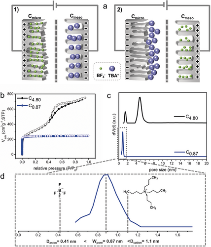
a) Schematic illustration of the working mechanism of CAPode: 1) Cmicro is positively charged and Cmeso negatively charged (forward bias, U>0). 2) Cmicro is negatively charged and Cmeso positively (reverse bias, U<0). b) N2 physisorption isotherms of C4.80 and C0.87 at 77 K. c) The corresponding DFT pore size distribution of C4.80 and C0.87. d) Size relationship for cation, anion, and the pore size in C0.87.
In our proof-of-concept asymmetric CAPode we use tetrabutylammonium tetrafluoroborate (TBABF4, 1 m) in acetonitrile (AN) as electrolyte, while mesoporous carbon CMK-3 (Table 1, C4.80) and microporous carbon fibers (C0.87) serve as dissimilar electrodes. According to N2 physisorption data, the textural characteristics of C4.80 show the expected type IV isotherm typical for an ordered mesopore architecture (Figure 1 b).8 C0.87 shows a characteristic type I(a) isotherm with a substantial uptake at low relative pressure, implying the predominant existence of micropores. The corresponding pore size distributions (PSD, Figure 1 c) show that the peak pore sizes are 0.87 and 1.5/4.8 nm for C0.87 and C4.80, respectively. Argon measurements at 87 K show similar results, but for C0.87 the PSD is slightly broader compared with that derived from N2 measurements (Figure S2 a in the Supporting Information). The ions TBA+ (1.1 nm) and BF4− (0.41 nm) can both enter C4.80, but only the BF4− anions fit into C0.87 (Figure 1 d, Table 1, and Table S1).
Sample[a] |
SA[b] |
Vmicro[c] |
V>1.1[d] |
Vmeso[e] |
Vtotal[f] |
dpeak |
|---|---|---|---|---|---|---|
|
[m2 g−1] |
[cm3 g−1] |
[cm3 g−1] |
[cm3 g−1] |
[cm3 g−1] |
[nm] |
C4.80 |
1153 |
0.13 |
1.1 |
0.98 |
1.11 |
1.5/4.80 |
C0.60 |
680 |
0.29 |
0.068 |
0.04 |
0.31 |
0.60 |
C0.87 |
806 |
0.36 |
0.011 |
0 |
0.36 |
0.87 |
C1.00 |
1307 |
0.57 |
0.187 |
0 |
0.57 |
1.00 |
- [a] Label Cx specifies x as the peak pore size dpeak from DFT theory. [b] SA specific surface area calculated using Brunauer-Emmett-Teller method applied in the relative pressure range of 0.05–0.2. [c] Vmicro cumulative pore volume up to 2 nm calculated by QSDFT method. [d] V>1.1 is the pore volume for pores larger than 1.1 nm. [e] Vmeso is the difference between Vtotal and Vmicro. [f] Vtotal is the cumulative pore volume extracted from the QSDFT method.
Prior to the full cell CAPode electrochemical characterization, individual symmetric cells of the two carbon materials were investigated (Figure S3). Symmetric cells based on C4.80 present the expected rectangular cyclic voltammograms, indicative of double layer behavior, while C0.87 shows only negligible capacitance, since the majority of pores are inaccessible for the large TBA+ cations (detailed in Supporting Information). For the CAPode concept, an asymmetric cell using C0.87 as working electrode and C4.80 as counter electrode was assembled. Figure 2 a gives typical cyclic voltammograms for the CAPode at varying scan rates. There is only negligible capacitance (current) in the negative voltage range as the bulky TBA+ cations cannot access the pores of C0.87 (referred to case 2 in Figure 1 a), except the minor region near 0 V, which is mainly attributed to the small amount of larger pores and external surface area in C0.87 (Figure 1 d and Figure S5) confirming the accuracy of pore size distributions derived by physisorption. At forward bias the small anions (BF4−) are stored in C0.87 and the large cations (TBA+) in C4.80 leading to a high capacity and the CV curve in this section exhibits a rectangular shape (case 1 in Figure 1 a) due to electric double layer formation on both electrodes.
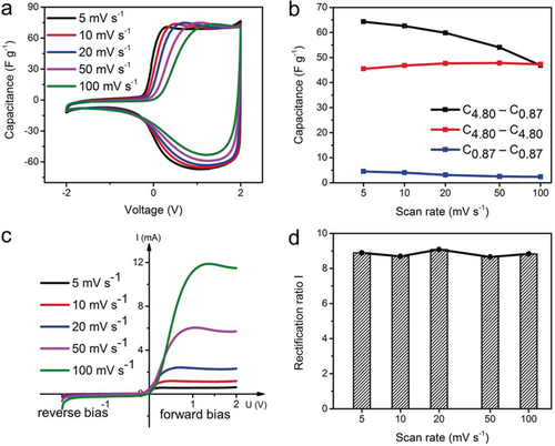
Electrochemical and “diode” performances of the CAPode C4.80| TBABF4(AN) |C0.87. The electrolyte concentration is 1 M. a) Cyclic voltammetry at varying scan rates. b) The capacitances between C0.87 and C4.80 based symmetric supercapacitor as well as the C4.80–C0.87 based CAPode at different scan rates. The capacitance for the CAPode is based on the positive part (0–2 V). c) I–U curves of CAPode at different scan rates. d) Rectification ratio I of the CAPode at varying scan rates, the points for RRI calculation are 1.5 V and −1.5 V for positive and negative charging, respectively.
As we increase the scan rate, the CAPode retains the asymmetric capacitive behavior (Figure 2 a), but decreases its overall capacitance (Figure 2 b). The main reason is the limited diffusion of BF4− anions in the small micropores of C0.87, which is inevitable for purely microporous carbon electrodes.9 Interestingly, the capacitances of CAPode at low scan rates are even higher than for both symmetric cells based on C4.80 and C0.87, respectively (Figure 2 b and Table 2), indicating the importance of size matching of anions and cations to the respective cathode and anode for increased electrode surface utilization and consequently enhanced capacity.
Cell type |
Electrodes |
Capacitance[a] F g−1 |
Rectification ratio I[b] |
Rectification ratio II[c] |
|---|---|---|---|---|
Symm. |
C4.80| TBABF4(AN) |C4.80 |
52 |
– |
– |
Symm. |
C0.87| TBABF4(AN) |C0.87 |
5 |
– |
– |
CAPode |
C4.80| TBABF4(AN) |C0.87 |
70 |
9 |
90 % |
Symm. |
C0.60| TBABF4(AN) |C0.60 |
6 |
– |
– |
CAPode |
C4.80| TBABF4(AN) |C0.60 |
65 |
12 |
90 % |
Symm. |
C1.00| TBABF4(AN) |C1.00 |
59 |
– |
– |
CAPode |
C4.80| TBABF4(AN) |C1.00 |
83 |
3 |
61 % |
- [a] Capacitance calculated here is based on the mass of Cmicro (equals to the mass of Cmeso) and in the positive scan range (0–2 V). In case of C1.00, the value is based on the range of 0–2.5 V. [b] Rectification ratio I is the current ratio at certain voltage when the response current reaches a plateau (1.5 V and −1.5 V for C4.80–C0.87 and C4.80–C0.60; 2.0 V and −2.0 V and for C4.80–C1.00). [c] Rectification ratio II is derived as the ratio of capacitance in the positive range versus the capacitance in the entire voltage range.
The asymmetric electrode assembly (CAPode) shows promising diode characteristics with high capacity, a decisive feature for CAPode applications such as alternating current (AC) rectification or alternative signal management.10 Due to the exclusion effect of cations from the small C0.87 electrode, ideal CAPode can only deliver current in one direction during charging. The current–voltage curves indicate the blocking efficiency of our CAPode (Figure 2 c). In contrast to semiconductor diodes, CAPodes allow backward and forward current, but only one (positive) bias direction is allowed. Hence, CAPodes traverse two times through almost identical charging states at one bias in the rectangular section of the CV. For simplification only one state is shown in Figure 2 c. In the negative bias range, there is almost no charging current across the CAPode. Only below −2 V, an insignificant current is detected potentially indicating parasitic electrolyte redox reactions. In the range of forward bias, an increasing scan-rate dependent current is observed reaching a plateau. CAPodes can not only rectify voltage but also stabilize currents, an important feature for grid stabilization. A high rectification ratio (RR) was calculated, using two methods, either RRI at defined voltage points (±1.5 V and ±2.0 V) or RRII derived from the integral positive vs. entire voltage range capacitance. A steady rectification ratio RRI=9 can be obtained at all scan rates (Figure 2 d). At this voltage the CAPode reaches a plateau and no obvious electrode polarization is observed (for ±2.0 V see Figure S6 a). We also calculated the positive voltage capacitance proportion (RRII) for the entire scan range to confirm the rectification performance (Figure S6 b). RRII is close to 90 % and constant at all scan rates, comparable to RRI at ±1.5 V. RRII decreases only by 0.41 % after 100 cycles (Figure S7). Moreover, in the galvanostatic charge-discharge measurements (Figure S8), we can confirm the high rectification ratio by comparing the positively and negatively polarized CAPode. The forward bias capacitance is even 15 times higher than the reverse bias capacitance, confirming the data from cyclic voltammetry. Traditional diode based devices typically reach rectification ratios of 40.5 % (half-wave) and 81 % (full-wave), however, these values are not directly comparable with RRII as they rely on a different operating mechanism.14
Tailoring electrode pore size distributions significantly affects the CAPode performance, as demonstrated by integrating microporous carbons with only slightly changed pore sizes compared to C0.87 into an asymmetric cell versus C4.80 using the same electrolyte TBABF4. C0.60 (Figure 3 a) has a relatively wide PSD but peaking at about 0.6 nm and the pore size is mainly below 1.2 nm, while C1.00 (Figure 3 b) contains large micropores centered at about 1.0 nm reaching up to 1.5 nm. The C0.60 based CAPode exhibits the same asymmetric behavior as C0.87 but the positive voltage capacitance drops more quickly at increasing scan rates as compared to a C0.87 based CAPode (Figure S9 b) due to the smaller pores in C0.60 (Table 1, Figure S1) reducing anion (BF4−) capacity in C0.60 significantly. The broad PSD contributes to undesired capacitance at reversed bias and the RR also slightly drops (Figure S9 a).
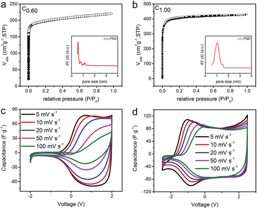
a) N2 physisorption isotherms at 77 K and the corresponding PSD (inset) for C0.60 b) N2 physisorption isotherms at 77 K and the corresponding PSD (inset) for C1.00. c) CV curves at varied scan rates for CAPodes C4.80| TBABF4(AN) |C0.60 and d) C4.80| TBABF4(AN) |C1.00.
The selectivity decrease is even more significant for C1.00 based CAPodes with additional larger micropores (>1.1 nm, Figure S1, Figure 3 d): At 5 mV s−1 the cut-off voltage significantly extends into the negative voltage range (−1 V). However, as scan rates rise, the onset of the diode behavior is shifted to higher voltage and at 100 mV s−1, CV curves are comparable to those of C0.87 based CAPodes, due to diffusion limitation of TBA+ cations in the larger micropores. The large mesopores in C4.80 offer enough space for fast anion diffusion and cannot be responsible for this shift. Interestingly, the positive voltage capacitances of both C0.60 and C1.00 based CAPodes are again higher than those of their symmetric cells (Table 2, Figure S4), further confirming the enhanced capacitive performance achieved by ion size matching in CAPodes.
Further tuning of the rectification characteristics is achieved by adjusting the electrolyte ion sizes (concentration: 1 m) for example, varying the cation size from TBA+ (1.1 nm) to tetrapropylammonium (TPA+, 0.92 nm) and tetraethylammonium (TEA+, 0.68 nm) in an asymmetric setup of C0.87 versus C4.80 (Table S1). The CV curves for TPA+ (Figure 4 a) are comparable to those observed for TBA+ (Figure 2 a) while TEA+ produces broader cyclic voltammograms in the range from −1 to 0 V (Figure 4 b). TPA+ and TBA+ reach almost the same RRII at varying scan rates but TEA+ delivers always smaller values (Figure 4 c). The latter can be ascribed to the extra accommodation of the smaller TEA+ ions in the C0.87 based CAPode when the device is negatively charged. The importance of size selective electroadsorption to achieve high RR values in CAPodes was further demonstrated using 1 m H2SO4 as electrolyte (Table S1). Since both the cation and anion are smaller than the pore size of C0.87, the asymmetric assembly performs with highly symmetric CV curves (Figure 4 d).
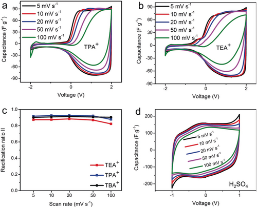
Electrochemical performance of C4.80–C0.87 based CAPodes using different electrolytes (1 m). a) Cyclic voltammetry at varied scan rates for TPABF4. b) Cyclic voltammetry at varied scan rates for TEABF4. c) The positive capacitance proportions (rectification ratio II) at different scan rates for the three electrolytes. d) Cyclic voltammetry curves for H2SO4.
To confirm the ion-selective adsorption mechanism proposed, the highest performing CAPode (C4.80| TBABF4(d-AN) |C0.87) was monitored via NMR spectroscopy. Firstly, 1H, 2H and 11B solid-state magic angle spinning nuclear magnetic resonance spectra (MAS NMR) were recorded without applied voltage. Each carbon material was loaded with 1 PV 1 m TBABF4 dissolved in d-AN (1 PV corresponds to the pore volume of the electrode). Measuring 1H, 11B, and 2H NMR spectra, the different electrolyte components could be studied selectively. NMR signals of species confined inside the pores of carbon materials show the characteristic diamagnetic shift caused by the ring-current effect.11 The 2H NMR spectra of carbon materials C0.87 and C4.80 exhibit one signal at chemical shifts clearly lower than the chemical shift of bulk electrolyte (Figure 5 a). This demonstrates that the d-AN molecules penetrate into the pores. The 1H and 11B NMR spectra of C4.80 (Figure 5 b,c) show signals for cations and anions confirming the penetration of all electrolyte components into the mesopores. A different behavior is observed for the microporous C0.87. The 1H NMR spectrum shows signals ascribed to protons in the carbon structure which exhibit chemical shift and line shape changes after electrolyte loading. These differences between pure and loaded material are likely to be due to interactions between protons of carbon material and acetonitrile as can be seen from the following discussion. The 1H NMR signal of the cations has a very low amplitude in C0.87. This is due to the low pore volume/size and indicates, furthermore, severe line broadening compared with C4.80. Their size prevents the cations from penetrating into the material, that is, they remain outside the particles. Although sufficiently small, the BF4− anions are then also prevented from entering the pores for charge balance reasons. This is indicated by the chemical shift of 11B exactly corresponding to the bulk value (Figure 5 c). In contrast, the negative 2H chemical shift (Figure 5 a) in C0.87 shows that acetonitrile molecules enter the pores. The ions remain outside thus forming a solvent-depleted external phase. The 1H NMR signals of this phase may thus be broadened making the cations practically undetectable in C0.87. In contrast, the electrolyte can access the pore system of C4.80 giving rise to the aforementioned, expected behavior, that is, decreasing chemical shifts compared with the bulk for all resonances.
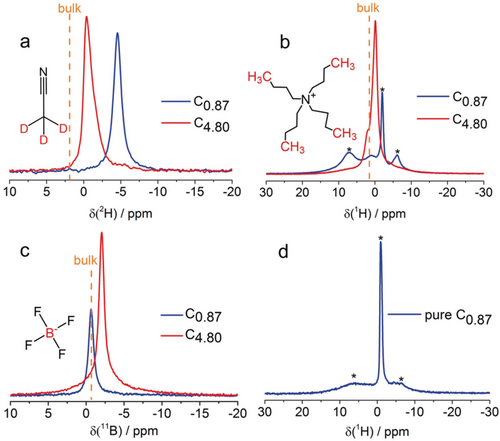
a) 2H, b) 1H, and c) 11B MAS NMR spectra of C0.87 (blue) and C4.80 (red) loaded with 1 m TBABF4 in d-AN. d) 1H spectrum of pure carbon material C0.87. Signals labeled with asterisks are characteristic for the carbon material.
The adsorption of BF4− anions inside individual electrodes of the CAPode device was further investigated by in situ NMR spectroscopy at varied voltage (Figure 6 and Figure S10). The CAPodes for those experiments were assembled such that only one electrode is detected by in situ NMR experiments in order to disambiguate spectra interpretation. Figure 6 a shows the spectra of the C0.87 electrode. As electrolyte, the cell contained 0.33 m TBABF4 dissolved in d-AN. It was loaded with a total volume corresponding to 7.5 PV. This higher volume at lower concentration is used to achieve complete wetting but simultaneously keep the amount of the electrolyte ions identical as in the static NMR measurements. For the whole applied voltage range (+2 V/ −2 V) in the spectra only one peak is detected centered around 2 ppm (Figure 6 a) indicating that adsorbed anions are not distinguishable from the bulk excess electrolyte. This effect could be explained by fast exchange between adsorbed and desorbed species and/or the pronounced line broadening in the absence of magic angle spinning.12 The applied voltage affects the chemical shift of BF4− in the following manner: Forward bias (U>0) results in a chemical shift decrease while δ(11B) increases for U<0. The chemical shift of nuclei in electrolytes adsorbed inside carbon materials is influenced by ring currents in the aromatic rings of the graphene-like walls giving rise to lower, even negative chemical shifts.15 It is established that the chemical shift decreases if the nuclei come closer to the walls.11a, 16 On the other hand, the presence of charges due to electric fields during the measurement could reduce the ring current shifts, that is, this would result in a higher chemical shift.17 The observation of a chemical shift decrease for U>0 in our spectra—despite the tentative charge influence—therefore indicates, that the BF4− ions on average come closer to the walls. This could be explained by a rearrangement of the electrolyte in the pores and/or the tendency of BF4− to preferentially occupy smaller pores at U>0. This effect is accompanied by pronounced increase of signal intensity for U>0 and a less pronounced decrease for U<0 compared to zero voltage (Figure 6). If the C4.80 electrode is placed inside the coil, a different behavior is observed (Figure S11). There is still one signal at around 2 ppm arising from the anions. Applying positive voltage does not lead to an accumulation of large amount of BF4− inside the electrode despite large pore size (the value of normalized integral is equal to 1 (Figure S11 b)). This is due to the fact that the cations are too large and cannot enter the small micropores of the C0.87-containing electrode. Almost no charge can now be stored inside the CAPode and both, anions and cations are predominantly found in the free bulk. If reversed bias is applied, the amount of anions decreases by about 40 % (Figure S11 b) indicating a fraction of anions to exit the negatively charged electrode and adsorb on the positively charged electrode. After discharging, an equilibrium state is reached.
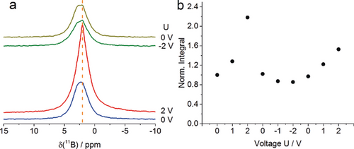
a) 11B in situ NMR spectra of the (C4.80| TBABF4(d-AN) |C0.87) CAPode. The electrode C0.87 is observed. b) Normalized integral of the 11B signal as a function of the applied voltage (U in Volt).
The NMR experiments clearly confirm the suppression of ion adsorption inside C0.87 without applied voltage, a result of charge balancing. Charge is only stored in the CAPode if the large cations are electrochemically attracted by the electrode C4.80. In contrast, no charge is stored at potentials where the large cations should be adsorbed inside C0.87. These observations confirm our hypotheses derived from electrochemical experiments.
Conclusion
The novel CAPode concept is a supercapacitor-based AC “ionic diode” analogue of DC semiconductor based diodes. In contrast to established semiconductor devices the storage mechanism allows forward and reverse current but only one polarization direction is permitted. This feature has high potential for AC rectification and simultaneous grid stabilization and buffering. A decisive CAPode prerequisite for high rectification ratios is at least one nanoporous electrode material with narrow pore size distribution for ion sieving to achieve a sharp cut-off at small pore size restricting the accessibility exclusively to the smaller anions. The counter electrode has a large pore size accessible for cations and anions. In theory, the inverse concept, using an anion significantly exceeding cation size would also be applicable. However, this approach is at current stage less variable in terms of availability of suitable electrolyte systems. The CAPode concept extends supercapacitors to new technological applications, for simultaneous energy storage and rectification. A series connection of an AC-power-source, CAPode, and load, leads to a half-wave modulation with integrated buffer and intrinsic voltage stabilization.
In future CAPodes may play a crucial role in ion-based logic circuits for energy efficient computing as efforts at miniaturization of electrochemical double layer capacitors are making great progress.13 Logic operations, such as AND, OR, NAND, are realized through combinations of diodes and transistors. Simultaneous information storage and logic operation is a crucial element of neuromorphic computing architectures.
Acknowledgements
We gratefully thank the Deutsche Forschungsgemeinschaft (Project No.: KA 1698/27-1) for financial support. K.K. is partially supported by JST OPERA project. We thank Kynol GmbH for providing active carbon fiber.
Conflict of interest
The authors declare no conflict of interest.


