
A feasibility study of a quantitative microwave tomography technique for structural monitoring
ABSTRACT
Quantitative microwave tomography is an imaging method based on the solution of a non-linear inverse scattering problem, which is able to provide an objective assessment of a region under test. Such a capability is relevant in the framework of non-destructive structural monitoring, where it allows to process ground-penetrating radar data so to achieve accurate information on the inner status of the probed structure. In this paper, we propose a two-step quantitative microwave tomography approach in which the morphological characterization of the targets is first pursued and then their electric contrast is determined by exploiting the information previously gained. A feasibility assessment of the proposed strategy is given against synthetic data concerning the imaging of a leaking pipeline embedded in a wall.
INTRODUCTION
The capability of electromagnetic waves to penetrate optically dense media is of practical importance for civil security purposes and damage monitoring. As a matter of fact, it provides a means to perform a non-destructive and minimal invasive screening of critical infrastructures, such as bridges, roads and historical monuments, with the possibility to promptly detect risk factors and timely address maintenance operations. In this framework, ground-penetrating radar (GPR) is one of the most feasible and widespread tools, which investigates the inner status of a natural or manmade structure by recording and processing the traveltime of the electromagnetic wave along the transmitter-target-receiver path (Daniels 2004). In particular, by shifting the antennas along the measurement line and joining together the acquired radar traces, an image, which is referred to as raw-data ‘radargram’, is provided.
However, despite their widespread adoption, GPR surveys are actually limited by the difficulties related to the interpretation of the radargrams, which strongly depends on the user’s expertise and its subjective evaluation. Moreover, a radargram does not allow to infer morphological and constitutive characterizations but only a rough localization of the detected anomalies. This drawback, jointly with the demand of exhaustive investigations, capable of providing as much information as possible on hidden objects, motivates an ongoing interest in developing advanced data processing strategies able to attain an objective assessment of the probed region. To achieve these added value results, imaging techniques based on the solution of an inverse scattering problem (Colton and Kress 1992) are worth considering, owing to their capability of providing information on both geometrical and constitutive features (i.e., the dielectric parameters) of targets. However, this processing of the measured scattered fields involves the non trivial task of solving a non-linear and ill-posed inverse problem (Bertero and Boccacci 1998).
In the last years, several efforts have been addressed to assess the performances of inverse scattering strategies against experimental data and in various applicative contexts, ranging from structural monitoring to archaeological investigations. In particular, in the framework of GPR surveys, it has been shown that linearized inverse scattering approaches are able to provide well-focused qualitative images from which buried structures can be reliably identified (Soldovieri et al. 2007; Pettinelli et al. 2009; Castaldo et al. 2009).
These results, together with the claim for exhaustive non destructive inspections able to provide information on the dielectric features of the detected targets, motivate an increasing interest in quantitative microwave tomography techniques, since these latter tackle the inverse scattering problem in its full complexity, thus offering enhanced reconstruction capabilities as compared to linearized approaches (Catapano et al. 2007; Crocco and Litman 2009).
However, quantitative microwave tomography procedures suffer the occurrence of false solutions, due to non-linearity of the problem at hand. Therefore, to improve the achievable performances and the reliability of the results, huge efforts have been addressed to understand the advantages offered by diversity in data acquisition (multifrequency/multistatic/multiview data) (Bucci et al. 2001; Persico et al. 2005) as well as on the analysis of the factors affecting the non-linearity of the relationship among data and unknowns (Isernia et al. 2001; Bucci et al. 2001). In addition, the progress in computational capabilities as well as the development of advanced GPR systems, designed to collect a larger amount of data (Counts et al. 2007), has made the stage of development a closer goal.
With respect to this framework, in this paper we propose a two-step quantitative microwave tomography strategy aimed at reconstructing the electric contrast distribution in the investigated region by taking advantage of a preliminary morphological characterization and by processing data collected under a multiview, multistatic and multifrequency measurement configuration. Since geometrical features of hidden objects are usually unknown, the first goal of the proposed strategy is to retrieve their presence, location and size. To this end, we exploit the linear sampling method (Cakoni and Colton 2006), which is a shape reconstruction technique able to deal with single or multiple dielectric and metallic targets. The second task that is the reconstruction of the contrast function, which encodes the dielectric features of the targets, is then pursued by looking for the global minimum of a regularized cost functional (Catapano et al. 2004) in which the ‘morphological’ information gained in the first step is properly embedded.
The advantages offered by the proposed imaging procedure are several. First of all, the imaging problem is split up into two subproblems whose solutions are simpler than the overall one. Second, the knowledge of the targets’ support gives some benefits in terms of a reduction of ill-conditioning and false solutions occurrence in the inversion, as was discussed and verified in Catapano et al. (2007). Third, in all those applicative contexts wherein a qualitative reconstruction is sufficient, only the first step has to be tackled, so reducing the overall computational burden and processing time.
The paper is organized as follow. In the next section the reference geometry and the adopted mathematical model are introduced with respect to the canonical 2D case and by assuming and dropping the time dependence factor  . The inversion procedure is described in the section ‘Inversion procedure’. In section ‘Feasibility assessment’ a proof of concept assessing the achievable reconstruction capabilities in the framework of masonry surveys is given by processing synthetic data concerning the pipe’s leak monitoring.
STATEMENT OF THE PROBLEM
The reference scenario considered in the following is sketched in Fig.1. The background medium is constituted by a three-layered medium, in which the middle layer is representative of the probed region and the first one is free-space. The third layer can be either free-space or another structure. The targets to be imaged (as well as the three layers) are supposed to be invariant along the  -axis of the considered right-handed coordinate system and the target’s cross-sections are supposed to be located within the investigated domain
  , embedded in the second layer.

Sketch of the reference scenario.
 ) and their complex equivalent permittivity is expressed through the ohmic dispersion rule:
 (1)
(1)where  is the free-space permittivity, while
  and
and  are the relative permittivity and DC conductivity, respectively. They are supposed to be frequency independent.
 the contrast function:
 (2)
(2)relates the complex equivalent permittivity of the targets,  , to that of the second medium,
  which is supposed to be homogeneous.
To probe the investigated region  , we assume that an array working in a multiview-multistatic stepped-frequency mode is used. Hence, for each frequency in the considered range, each antenna works as a transmitter and receiver and when one antenna transmits all others collect the data. The array is located in the first layer along the rectilinear domain
  placed close to the first interface and it is made of
  evenly spaced antennas, while the exploited bandwidth
  is evenly sampled through
  frequencies.
 as the incident field due to the
  -th antenna of the array at the generic angular frequency
  , the corresponding pair of equations is (Balanis 1989):
 (3)
(3) (4)
(4)where  represents the two-dimensional Green function for a layered medium at the considered angular frequency (Chew 1995) and
  is the wavenumber in the second medium.
  and
and  denote the scattered and the total fields corresponding to the incident field
  ), respectively. Equation (3) is named the observation or data equation whereas equation (4) is the object or state equation.
 in terms of that at the maximum frequency in
  , as:
, as:
 (5)
(5)where  ,* stands for the conjugation and
  synthetically denotes the operator that transforms
  into the contrast at the desired angular frequency.
 from the collected multiview, multistatic and multifrequency scattered field data. By adopting an operator notation, the problem is thus synthetically cast for each transmitter
  and at each frequency
  as:
as:
 (6)
(6) (7)
(7)where  and
and  are the internal and external radiation operators that provide the scattered field in
  and on
  , respectively.
INVERSION PROCEDURE
Morphology estimation: the linear sampling method
The first step of the proposed imaging strategy aims at retrieving geometrical features of objects embedded in  and it is based on the linear sampling method (Cakoni and Colton 2006). In the following, we briefly recall the ratio and the implementation of this method, by referring the reader to Cakoni and Colton (2006) for a detailed description of the mathematical theory and to Catapano et al. (2007) for a physical interpretation of the linear sampling method, which provides a general basis for its applicability, as shown in Catapano and Crocco (2009) and Catapano et al. (2008).
The idea underling the linear sampling method is to sample the investigated region into a grid of points and, for each of them, look for a superposition of the scattered fields such to match the field radiated by an elementary source located in the sampling point1. The better the match occurs, the higher the degree of affiliation of the point to a scatterer.
 be the monochromatic
  multistatic response data matrix, whose generic element,
  , is the scattered field at the
  -th receiver for the
  -th transmitter and the selected frequency. For an arbitrary grid of points that samples the investigated region
  , the linear sampling method requires to solve, in each sampling point
  the matrix equation:
 (8)
(8)where  is the
  -dimensional unknown vector and the
  -dimensional vector
  contains the values of the field radiated at the
  receiving positions on
  by an elementary source located in
  , when the targets are not present in
  . It is worth remarking that the linearity of the problem to be solved is exact, i.e., it does not descend from approximations on the scattering phenomenon (Cakoni and Colton 2006).
 (9)
(9)can be assumed as an indicator of objects location and morphology.
 equation (8) is solved through the singular value decomposition (SVD) (Colton and Kress 1992) of
  and the Tikhonov regularization (Colton and Kress 1992). By doing so, one obtains the following explicit expression for the linear sampling method indicator:
 (10)
(10)where  are the singular values of the multistatic response data matrix,
  are the left singular vectors;
  is the Tikhonov weighting coefficient, while
  and
and  denote the scalar product and the
  norm, both defined on
  , respectively.
 blowing up owing to the decreasing behaviour of the singular values of
  with respect to the scalar product appearing in equation (10). Such an observation suggests that, despite the standard implementation of the linear sampling method requires to compute the coefficient
  for each sampling point by means of the Morozov’s discrepancy principle (Cakoni and Colton 2006), the same
  can be actually used for all the
  . In particular, a practical criterion to choose
  is to take it such that (Catapano et al. 2008):
 (11)
(11)where the overline stands for the average as computed on the sampling grid. By doing so, one implicitly accounts for the presence of noise that corrupts  (and its SVD) but does not need an explicit knowledge of the noise level. Moreover, to avoid computing the regularizing parameter in each sampling point, the computational efficiency of the method is further increased allowing quasi real-time results.
 located far from
  . This effect is similar to what happens in the subsurface imaging case (Catapano et al. 2008) and can be mitigated by considering the modified indicator:
 (12)
(12) (13)
(13)which continuously varies between 0–1 and assumes larger values in points belonging to the scatterers.
Constitutive assessment: the ‘bilinear’ method
 . To pursue this goal, the multiview-multistatic-multifrequency data are simultaneously processed by means of a full-wave inversion procedure belonging to the class of modified gradient methods (Van den Berg and Kleinman 1997; Isernia et al. 1997). In this class of approaches both equations (6) and (7) are minimized in the least square sense and both the contrast function
  and the total fields in
  are considered as unknowns. Although this leads to an increase in the number of unknowns, it allows to reduce the overall non-linearity of the problem, with beneficial effects on the false solution occurrence2. Therefore, the inverse scattering problem is faced as the minimization of the cost functional (Catapano et al. 2004):
 (14)
(14) and
and  are the number of frequencies and primary sources, respectively. The residual errors with respect to state equation (7),
  and the data equation (6),
  , as well as the normalization terms
  and
and  are defined as follows:
 (15)
(15) (16)
(16) (17)
(17)To tackle the ill-posedness arising from the finite amount of data, a regularization by projection is introduced (Bertero and Boccacci 1998). In this way, the unknown functions are projected over a suitable basis and the resulting coefficients are taken as problem unknowns. Hence, we look for a finite dimensional representation for both the unknowns. In particular, the total electric field is represented by means of discrete spatial Fourier harmonics defined over the grid sampling  , while a wavelet basis (Vetterli and Kovacevic 1995) is used for the contrast function
  . Such a choice is determined by the advantages offered by a wavelet basis in representing functions exhibiting discontinuities and sharp peaks. Accordingly,
  can be well approximated by means of a reduced number of wavelet coefficients. By exploiting the information provided by the linear sampling method, these coefficients are distributed in a nonuniform way inside
  and concentrated in the region wherein the anomalies are expected to be located.
 can be regarded as a piecewise function and an additional term, which enforces the expected nature of the contrast, is introduced in the expression of the cost functional. Hence, the final expression of the cost functional to minimize is (Catapano et al. 2004):
 (18)
(18) denotes the number of sub-domains
  where the regularization term acts, while the quantity
  in the second term on the right-hand side is:
 (19)
(19) , being the homogeneous contrast, at the higher processed frequency, pertaining to the objects expected to be in the generic sub-domain
  and
and  is the number of pixels belonging to
  . It is worth noting that different regularizing terms act in each subdomain partitioning
  by forcing, in each pixel, the values of the reconstructed contrast to be 0 or
  . The regions
  can be selected by exploiting a priori knowledge on the investigated scenario or the information provided by the linear sampling method. On the other hand,
  can be either known or unknown.
The optimization problem is iteratively faced by means of the conjugate gradient procedure, whose implementation is made effective owing to an extensive use of fast Fourier transform codes (Catapano et al. 2004). Moreover, since the multi-frequency data can be processed in an almost independent fashion, the processing time can be further reduced by exploiting a parallelized encoding.
FEASIBILITY ASSESSMENT
To assess the reconstruction capabilities of the proposed strategy, we illustrate three examples concerning the monitoring of a purely dielectric plastic pipe  . The external radius of the pipe is
  and the internal one is
  . The pipe contains a fluid having
  and
and  , which are close to those of oil petroleum and it is located in a concrete wall, 50 cm thick, whose dielectric parameters, in the investigated region, randomly vary around their average values (
 and
and  ) with deviation of ±10%. Note we have assumed that the frequency dependence of the involved materials is described by the complex equivalent permittivity given in equation (1).
The data are supposed to be collected at  ,
,  and
and  by using
  transmitting and receiving antennas uniformly spaced on a line
  1 m long located close to the air-wall interface (see Fig. 2a). Synthetic data have been generated by means of a method of moments-based full-wave forward solver and corrupted with an additive Gaussian noise, to account for the unavailable measurement noise. The signal-to-noise ratio is
  .
.

Case 1: imaging of an undamaged pipe. a) Reference distribution: map of  ; b) morphological reconstruction: plot of
  ; c) quantitative reconstruction: map of
  .
.
In the following, a rectangular domain 1 m × 0.5 m is taken as the investigated region  and it is partitioned into 64 × 32 square pixels. The actual unknown of the inverse problem is
  , i.e., the contrast function at 600 MHz.
 , is shown, the imaginary part being negligible. Moreover, the reconstruction capabilities are quantitatively assessed by means of the reconstruction error:
 (20)
(20) being the reconstructed contrast function.
As a fist example, let us suppose that an undamaged pipe is located in  , as Fig. 2(a) shows. Herein, the colourbar denotes the actual values of
  in
in  .
.
According to the proposed procedure, the data collected at  are initially processed by means of the linear sampling method. The indicator
  is shown in Fig. 2(b), where the colour bar is referred to as the dynamic range of
  . Since the latter is expected to approach 1 when
  belongs to the targets, from Fig. 2(b) one can state that an object is located in the region [–0.15, 0.05] m × [0.0, 0.25] m. Such information is exploited in the second step to restrict the spatial domain wherein the contrast wavelet coefficient unknowns are looked for. In this respect, a first level coarse wavelet representation is adopted and the DAUB20 wavelet, belonging to the Daubechies family, is used as the mother wavelet. In addition, the regularization term is such to act in a region
  completely covering
  , the positive weight factor
  is fixed equal to 0.09 and a priori information on the electric features of the pipe are exploited to set the value of
  . By doing so an accurate image of the pipe is obtained, as Fig. 2(c) shows. In particular, by comparing Fig. 2(c), where the colour bar is referred to as
  , with Fig. 2(a) one can state that a quantitative reconstruction is achieved. As a matter of fact,
  approaches –0.5 in points belonging to the pipe and zero elsewhere and the reconstruction error is err = 0.31.
It is worth noting that the choice of the weighting coefficients  is a critical point, since in the framework of non-linear problems, such as the one at hand, as general no rule exists to perform an optimal choice. A possible strategy to fix their value is to exploit a statistical analysis (Pascazio and Ferraiuolo 2003). However, this study is beyond the aim of this paper and in the following
  are heuristically fixed (
 ).
).
Now, let us consider a damaged pipe and suppose that the concrete is fluid-soaked. To this end, a rectangular object 0.21 m × 0.06 m having electric parameters  and
and 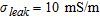 is added in the region under test to represent a leak, as Fig. 3(a) shows. Despite an accurate model of a leaking pipeline requires the use of a suitable mixing formula to set the dielectric features of the leak, in order to provide proof of the concept of the achievable performances, it has been herein arbitrarily chosen.

Case 2: imaging of a damaged pipe. The leakage is modelled as a fluid and concrete mixture. a) Reference distribution: map of  ; b) morphological reconstruction: plot of
  ; c) quantitative reconstruction: map of
  .
.
Figure 3(b) shows that the reconstruction provided by the linear sampling method not only allows us to detect and approximately localize the pipe but also suggests that an anomaly is present. According to this result, the second step is carried out by looking for the wavelet coefficients corresponding to the region [–0.15, 0.15] m × [0.0, 0.42] m. Again, a first level coarse representation is used and the DAUB20 is chosen as the mother wavelet. In order to separately image the pipe and the leak, the regularization term in equation (18) is defined by considering two different regions  and
and  , which are selected by exploiting the information provided by the linear sampling method. In particular,
  denotes the sub-domain [–0.15, 0.15] m – [0.0, 0.25] m where the pipe is supposed to lie, while
  is the region [–0.5, 0.5] m × [0.25, 0.5] m, where the leak is expected. This appears a reasonable hypothesis, since the images given in Fig. 3(b) suggest that the pipe is located in the shallower part of
  . As in the previous example, the electric features of the pipe are supposed to be given, hence the value of the contrast
  , appearing in the regularization term acting on
  is assumed to be known. On the other hand, since we assume that no a priori information on the electric features of the leak is available, the value of
  in equation (18) is taken as a further unknown.
The real part of the reconstructed contrast function,  is given in Fig. 3(c), which shows that
  approximates –0.5 in points belonging to the pipe, its maximum value in the region of the leak is 0.27 (while the actual one is 0.29) and it is zero elsewhere. Hence, a quantitative characterization is actually possible also in this more complex scenario. Moreover, the size of the leak in the
  -direction is well retrieved while that along the
  -axis is underestimated. In this case the reconstruction error is err = 0.34.
To further stress the reconstruction capabilities of the proposed strategy, let us consider the case of a cavity, 0.21 m × 0.06 m large located behind the pipe and consider this cavity completely filled by the leaked fluid. As such, the ‘leak target’ has the same electric features of the fluid, see Fig. 4(a). As in the previous example, the linear sampling method allows detecting an anomaly behind the pipe as shown in Fig. 4(b), so identifying the region wherein the contrast unknowns have to be concentrated and the sub-domains wherein the regularization term has to act. In this case,  and
and  are the sub-domains [–0.5, 0.5] m × [0.0, 0.35] m and [–0.5, 0.5] m × [0.35, 0.5] m, respectively, the wavelet coefficients are looked for in the region [–0.15, 0.15] m × [0.0, 0.5] m and
  is assumed as unknown. Figure 4(c) shows that a quantitative reconstruction of the leak is again achieved, indeed a target approximately 0.15 cm × 5 cm in size and such that
  –0.5 appears close to the pipe. However, in this case the reconstruction error is higher than in the previous examples, being err = 0.43.

Case 3: imaging of a damaged pipe. The leakage fills a cavity so that its dielectric features are those of the fluid inside the pipe. a) Reference distribution: map of  ; b) morphological reconstruction: plot of
  ; c) quantitative reconstruction: map of
  .
.
CONCLUSIONS
Moving towards objective GPR surveys capable of achieving accurate images of the investigated regions, a two-step quantitative microwave tomography strategy has been proposed. In particular, the imaging problem has been split into two subproblems. The first one pursues a morphological characterization by means of the linear sampling method, while the second one addresses the reconstruction of the electric contrast function. To cope with this task, a modified gradient approach, exploiting the morphological characterization gained in the first step as well as suitable regularization techniques, has been taken into account. Such an approach takes advantage of frequency diversity without neglecting the dispersive behaviour of the probed media, provided that it is described by a known constitutive relationship. In this paper an ohmic dispersion rule has been assumed, since it is a reasonable hypothesis in many applications. However, the approach can be extended to more sophisticated dispersion models.
A preliminary assessment of the performances of the proposed strategy has been given against numerical data mimicking structural monitoring scenarios. The obtained results, which have shown that a quantitative reconstruction of the contrast function distribution is actually feasible, suggest to further investigate the achievable reconstruction capabilities. Therefore, future work will be aimed at considering more complex scenarios and experimental data. Moreover, the formulation of the strategy in the three-dimensional vectorial case will be addressed.
REFERENCES
- 1 This field corresponds to the background Green function (Chew 1995) of the scenario under test (a three-layer medium in the case at hand).
- 2 As a matter of fact, the integral operators
 and
and  are bilinear with respect to the unknown pair
  and
and  , being linear operators with respect to the product