Mixed Convection Boundary Layer Flow from a Solid Sphere with Newtonian Heating in a Micropolar Fluid
Abstract
The steady mixed convection boundary layer flow from a solid sphere in a micropolar fluid, generated by Newtonian heating in which the heat transfer from the surface is proportional to the local surface temperature, is considered. The governing boundary layer equations are first transformed into a system of nondimensional equations via the non-dimensional variables, and then into nonsimilar equations before they are solved numerically using an implicit finite-difference scheme known as the Keller-box method. Numerical solutions are obtained for the skin friction coefficient, wall temperature and heat transfer coefficient, as well as the velocity and temperature profiles with several parameters considered, namely the mixed convection parameter, the material or micropolar parameter, and the Prandtl number.
1. Introduction
The essence of the theory of micropolar fluid flow lies in the extension of the constitutive equation for Newtonian fluid, so that more complex fluids such as particle suspensions, liquid crystal, animal blood, lubrication, and turbulent shear flows can be described by this theory. The theory of micropolar fluid was first proposed by Eringen [1]. Extensive review of the theory and applications can be found in the review article by Ariman et al. [2] and quite recent papers by Rees and Bassom [3], Pop et al. [4], Nazar et al. [5–8], and so forth. This clearly shows the fast development of the theory of micropolar fluid. In summary, all the papers above considered the boundary condition of either a constant wall temperature or constant heat flux.
Generally, in modeling the boundary layer flow and heat transfer of these problems, the boundary conditions that are usually applied are either a constant wall temperature (CWT) or a constant wall heat flux (CHF). However, there is a class of boundary layer flow and heat transfer problems in which the surface heat transfer depends on the surface temperature. Perhaps the simplest case of which is when there is a linear relation between the surface heat transfer and surface temperature. This situation arises in conjugate heat transfer problems (see, e.g., Merkin and Pop [9]), and also when there is Newtonian heating of the convective fluid from the surface. The latter case has been first discussed in detail by Merkin [10]. The situation with Newtonian heating arises in what are usually termed conjugate convective flows, where the heat is supplied to the convecting fluid through a bounding surface with a finite heat capacity. This results in the heat transfer rate through the surface being proportional to the local difference in the temperature with the ambient conditions. However, the Newtonian heating conditions have been used only recently by Lesnic et al. [11–13] and Pop et al. [14] to study the free convection boundary layer over vertical and horizontal surfaces as well as over a small inclined flat plate from the horizontal surface embedded in a porous medium. The asymptotic solution near the leading edge and the full numerical solution along the whole plate domain have been obtained numerically, whilst the asymptotic solution far downstream along the plate has been obtained analytically. Chaudhary and Jain [15, 16] studied the unsteady free convection boundary layer flow past an impulsively started vertical infinite flat plate with Newtonian heating.
This configuration occurs in many important engineering devices, for example, in heat exchanger where the conduction in solid tube wall is greatly influenced by the convection in the fluid flowing over it. Furthermore, for conjugate heat transfer around fins where the conduction within the fin and the convection in the fluid surrounding it must be simultaneously analyzed in order to obtain the vital design information and also in convection flow setup when the bounding surfaces absorb heat by solar radiation [15, 16]. This results in the heat transfer rate through the surface being proportional to the local difference in the temperature with the ambient conditions.
Recently, Salleh et al. [17, 18] employed an implicit finite-difference scheme, namely the Keller-box method to obtain numerical solutions for mixed convection boundary layer flow near the lower stagnation point of a solid sphere and forced convection boundary layer flow at a forward stagnation point with Newtonian heating in viscous fluids, respectively.
Therefore, the aim of the present paper is to study the problem of mixed convection boundary layer flow from a solid sphere with Newtonian heating in a micropolar fluid. The governing boundary layer equations are first transformed into a system of non-dimensional equations via the non-dimensional variables, and then into non-similar equations before they are solved numerically by the Keller-box method, as described in the books by Na [19] and Cebeci and Bradshaw [20]. To the best of our knowledge, this present problem (for the case of Newtonian heating) has not been considered before, so that the reported results are new.
2. Analysis
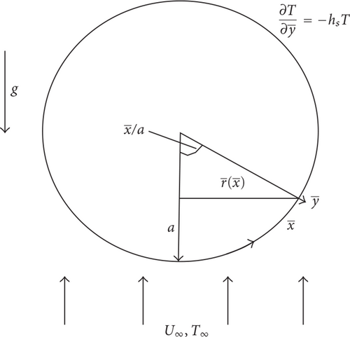
Consider a heated sphere of radius a, which is immersed in a viscous and incompressible micropolar fluid of ambient temperature T∞, which is subjected to a Newtonian heating (NH) as shown in Figure 1. The convective forced flow is assumed to be moving upward, while the gravity vector g acts downward in the opposite direction, where the coordinates and are chosen such that measures the distance along the surface of the sphere from the lower stagnation point and measures the distance normal to the surface of the sphere. We assume that the equations are subjected to a Newtonian heating of the form proposed by Merkin [10]. Under the Boussinesq and boundary layer approximations, the basic equations are (Nazar et al. [6, 8])
Let be the radial distance from the symmetrical axis to the surface of the sphere and the local free stream velocity, which are given by
We introduce now the following non-dimensional variables:
Further, the stream function ψ is introduced and it is defined as
Equations (6) to (8) then become
At the lower stagnation point of the sphere, x ≈ 0, (13) reduces to the following ordinary differential equations:
The quantities of physical interest are the skin friction coefficient, Cf and the local wall temperature distribution, θw(x), which are given by
3. Solution Procedure
Equations in (13) subject to the boundary conditions (14) are solved numerically using the Keller- box method as described in the books by Na [19] and Cebeci and Bradshaw [20]. The solution is obtained in the following four steps.
- (i)
Reduce (13) to a first-order system.
- (ii)
Write the difference equations using central differences.
- (iii)
Linearize the resulting algebraic equations by Newton’s method, and write them in the matrix-vector form.
- (iv)
Solve the linear system by the block tridiagonal elimination technique (see Salleh et al. [25] for the details of this method).
4. Results and Discussion
Equations in (13) subject to the boundary conditions (14) are solved numerically using an efficient implicit finite-difference scheme with various parameters, namely the mixed convection or buoyancy parameter λ, the material or micropolar parameter K and the Prandtl number Pr. In this paper, the numerical solutions start at the lower stagnation point of the sphere, x ≈ 0, as given in (15) subjects to the boundary conditions (16) and proceed round the sphere up to the separation point xs. The values of the skin friction coefficient, Cf and the local wall temperature distribution, θw(x) have been obtained at different positions 0 ≤ x ≤ 1200 for following values of the material parameter K = 0 (Newtonian fluid), 1, 2, and 3 (micropolar fluid), with various values of the mixed convection parameter λ. It should be noticed that the present results were obtained up to the value of x = 1200, as given by Nazar et al. [6, 8]. Values of Pr considered are Pr = 0.7, 1, and 7 which correspond to air, electrolyte solution and water, respectively.
Due to the decoupled boundary layer equation (15) when the mixed convection parameter λ = 0 and K = 0, there is a unique value of the reduced skin friction coefficient, f′′(0) = 2.4104 for all Prandtl number Pr, which is in good agreement with the value f′′(0) = 2.4151 found by Nazar et al. [6–8]. The values of f′′(0), −θ′(0) and θ(0) for the cases of CWT, CHF, and NH are shown in Tables 1, 2, and 3, respectively. Some results reported by Nazar et al. [6, 8] for the cases of CWT and CHF and Salleh et al. [17] for the case of NH in viscous fluid (K = 0) are also included in these tables. It is found that the agreement between the previously published results with the present ones is very good. We can conclude that this method works efficiently and we are also confident that the results presented here are accurate.
Tables 4(a) and 4(b) show comparisons on the values of θ(0) and −θ′(0) as well as f′′(0), respectively, for different boundary conditions (CWT, CHF, and NH cases) with fixed Pr = 7 and K = 1 (micropolar fluid). Table 4(a) shows the values of the heat transfer coefficient −θ′(0) for the case of CWT, the wall temperature θ(0) for the case of CHF, and the wall temperature θ(0) or the heat transfer coefficient −θ′(0) for the case of NH. It is noticed from Table 4(a) that for the case of CWT, as λ increases, the heat transfer coefficient −θ′(0) also increases. This table also shows that for the case of CHF, as λ increases, the wall temperature θ(0) decreases. However, for the case of NH, as λ increases, both the heat transfer coefficient and the wall temperature decrease. The trend for NH case is similar to the CHF case but different from the CWT case. On the other hand, Table 4(b) shows the values of the skin friction coefficient f′′(0) for the cases of CWT, CHF, and NH. It shows that for all the three cases, as λ increases, the skin friction coefficient f′′(0) also increases. The trend for NH case is similar to the CWT and CHF cases, but the values of f′′(0) are closer to the CWT case than the CHF case.
| λ | CWT | CHF | NH | |
|---|---|---|---|---|
| −θ′(0) | θ(0) | θ(0) | −θ′(0) | |
| −2.0 | 1.6670 | 0.5878 | — | — |
| −1.0 | 1.6980 | 0.5847 | — | — |
| 0.0 | 1.7272 | 0.5790 | 1.2748 | 2.2748 |
| 2.0 | 1.7805 | 0.5688 | 1.2410 | 2.2410 |
| 4.0 | 1.8286 | 0.5598 | 1.1750 | 2.1750 |
| 6.0 | 1.8725 | 0.5517 | 1.1190 | 2.1190 |
| 8.0 | 1.9159 | 0.5445 | 1.0745 | 2.0745 |
| 10.0 | 1.9509 | 0.5379 | 1.0378 | 2.0378 |
| 20.0 | 2.1101 | 0.5115 | 0.9165 | 1.9165 |
| λ | CWT | CHF | NH |
|---|---|---|---|
| f′′(0) | f′′(0) | f′′(0) | |
| −2.0 | 1.4748 | 1.6244 | — |
| −1.0 | 1.6179 | 1.6761 | — |
| 0.0 | 1.7568 | 1.7568 | 1.7568 |
| 2.0 | 2.0236 | 1.9102 | 2.1176 |
| 4.0 | 2.2785 | 2.0547 | 2.3937 |
| 6.0 | 2.5235 | 2.1918 | 2.6367 |
| 8.0 | 2.7603 | 2.3227 | 2.8568 |
| 10.0 | 2.9901 | 2.4483 | 3.0597 |
| 20.0 | 4.0590 | 3.0160 | 3.9136 |
The values of f′′(0) and θ(0) for various values of λ, K and Pr are shown in Tables 5 and 6, respectively. From Table 5, it is found that as K increases, the values of f′′(0) are higher and θ(0) are lower for K = 1 than those for K = 2 and 3. On the other hand, from Table 6, it can be seen from this table that the values of f′′(0) and θ(0) are higher for Pr = 0.7 than those for Pr = 1 and 7.
| λ | K = 1 | K = 2 | K = 3 | |||
|---|---|---|---|---|---|---|
| f′′(0) | θ(0) | f′′(0) | θ(0) | f′′(0) | θ(0) | |
| 0.05 | 1.7662 | 1.3736 | 1.4597 | 1.5677 | 1.2777 | 1.7382 |
| 1.0 | 1.9332 | 1.2988 | 1.5980 | 1.4970 | 1.3990 | 1.6551 |
| 5.0 | 2.4950 | 1.1527 | 2.0583 | 1.3055 | 1.7992 | 1.4333 |
| 7.0 | 2.7268 | 1.1019 | 2.2469 | 1.2450 | 1.9623 | 1.3643 |
| 10.0 | 3.0386 | 1.0378 | 2.5001 | 1.1755 | 2.1807 | 1.2853 |
| λ | Pr = 0.7 | Pr = 1 | Pr = 7 | |||
|---|---|---|---|---|---|---|
| f′′(0) | θ(0) | f′′(0) | θ(0) | f′′(0) | θ(0) | |
| 0.05 | 5.3893 | 582.9966 | 3.3508 | 269.9892 | 1.4597 | 1.5677 |
| 1.0 | 5.9345 | 33.9767 | 4.0100 | 18.9700 | 1.5980 | 1.4970 |
| 5.0 | 7.5188 | 9.7701 | 5.5475 | 6.5872 | 2.0583 | 1.3055 |
| 7.0 | 8.1221 | 7.8312 | 6.0922 | 5.4627 | 2.2469 | 1.2450 |
| 10.0 | 8.9099 | 6.2842 | 6.7908 | 4.5284 | 2.5001 | 1.1755 |
Tables 7 and 8 show the values of Cf and θw(x) for Pr = 0.7, K = 1 (micropolar fluid) and various values of λ, respectively. It can be seen from these tables that as the parameter λ increases, Cf increases while θw(x) decreases. The actual value of λ = λk, which first gives no separation is difficult to determine exactly as it has to be found from the equations. However, the numerical solution indicates that the value of λk which first gives no separation lies between 0.05 and 1 for fixed Pr = 0.7 and K = 1.
| x | λ | |||||
|---|---|---|---|---|---|---|
| 0.005 | 0.02 | 0.05 | 1 | 5 | 7 | |
| 00 | 0.0000 | 0.0000 | 0.0000 | 0.0000 | 0.0000 | 0.0000 |
| 100 | 2.2261 | 2.2280 | 2.2319 | 2.2995 | 2.5190 | 2.5862 |
| 200 | 4.6769 | 4.6803 | 4.6870 | 4.8001 | 5.1915 | 5.3111 |
| 300 | 7.0750 | 7.0797 | 7.0889 | 7.2419 | 7.7920 | 7.9602 |
| 400 | 9.4615 | 9.4673 | 9.4789 | 9.6676 | 10.3657 | 10.5797 |
| 500 | 11.6907 | 11.6976 | 11.7113 | 11.9338 | 12.7718 | 13.1966 |
| 600 | 13.7553 | 13.7631 | 13.7788 | 14.0312 | 15.0807 | 15.8120 |
| 700 | 15.7534 | 15.7622 | 15.7796 | 16.0600 | 17.4505 | 18.2886 |
| 800 | 17.4679 | 17.4775 | 17.4965 | 17.8096 | 19.4869 | 20.3704 |
| 900 | 19.0260 | 19.0362 | 19.0566 | 19.4335 | 21.2685 | 22.1885 |
| 1000 | 20.2155 | 20.2370 | 20.6934 | 22.5758 | 23.5257 | |
| 1100 | 21.1823 | 21.6963 | 23.5557 | 24.5200 | ||
| 1200 | 22.1532 | 23.9418 | 24.8979 |
| x | λ | |||||
|---|---|---|---|---|---|---|
| 0.005 | 0.02 | 0.05 | 1 | 5 | 7 | |
| 00 | 3972.1601 | 997.6703 | 402.7344 | 24.9385 | 7.7892 | 6.3404 |
| 100 | 14946.0423 | 3741.4930 | 1500.5887 | 78.2596 | 18.0482 | 13.3545 |
| 200 | 15962.9645 | 3995.3036 | 1601.7763 | 82.9188 | 18.8185 | 13.8678 |
| 300 | 16578.9876 | 4149.1161 | 1663.1461 | 85.8007 | 19.3253 | 14.2146 |
| 400 | 17114.5642 | 4282.9142 | 1716.5875 | 88.3705 | 19.8096 | 14.5542 |
| 500 | 17663.7427 | 4420.1691 | 1771.4575 | 91.0592 | 20.3424 | 14.8667 |
| 600 | 18250.9445 | 4566.9709 | 1830.1793 | 93.9733 | 20.9019 | 15.0610 |
| 700 | 18940.4194 | 4739.3755 | 1899.1698 | 97.4257 | 21.4484 | 15.3222 |
| 800 | 19744.1335 | 4940.3723 | 1979.6231 | 101.4657 | 22.0515 | 15.7276 |
| 900 | 20692.2273 | 5177.4964 | 2074.5533 | 106.1772 | 22.8095 | 16.2955 |
| 1000 | 5460.6204 | 2187.9111 | 111.7045 | 23.7877 | 17.0402 | |
| 1100 | 2324.9537 | 118.3370 | 25.0444 | 17.9891 | ||
| 1200 | 126.5161 | 26.6599 | 19.1931 |
Tables 9 and 10 present the values of the local skin friction coefficient Cf and the wall temperature distribution θw(x) for λ = 1, K = 1 and various values of Pr, respectively. It is found that, for fixed λ = 1 and K = 1, as Pr increases, both the Cf and θw(x) decreases. On the other hand, for fixed Pr, as x increases, that is, from the lower stagnation point of the sphere, x ≈ 0, and proceeds round the sphere up to the point, x = 1200, both the values of Cf and θw(x) increase.
| x | Pr | ||
|---|---|---|---|
| 0.7 | 1 | 7 | |
| 00 | 0.0000 | 0.0000 | 0.0000 |
| 100 | 2.2995 | 1.5053 | 0.1490 |
| 200 | 4.8001 | 3.1609 | 0.3806 |
| 300 | 7.2419 | 4.7598 | 0.5211 |
| 400 | 9.6679 | 6.3723 | 0.7668 |
| 500 | 11.9338 | 7.8549 | 0.8887 |
| 600 | 14.0312 | 9.2817 | 1.0657 |
| 700 | 16.0600 | 10.7771 | 1.3207 |
| 800 | 17.8096 | 12.0495 | 1.4135 |
| 900 | 19.4335 | 13.2069 | 1.6429 |
| 1000 | 20.6934 | 14.0239 | 1.6813 |
| 1100 | 21.6963 | 14.6790 | 1.8646 |
| 1200 | 22.1532 | 14.9131 | 1.9266 |
| x | Pr | ||
|---|---|---|---|
| 0.7 | 1 | 7 | |
| 00 | 24.9385 | 13.7810 | 1.2988 |
| 100 | 78.2596 | 47.5798 | 3.4913 |
| 200 | 82.9188 | 50.5583 | 3.8423 |
| 300 | 85.8007 | 52.3905 | 4.0603 |
| 400 | 88.3705 | 54.0104 | 4.2166 |
| 500 | 91.0592 | 55.6998 | 4.3814 |
| 600 | 93.9733 | 57.4598 | 4.5348 |
| 700 | 97.4257 | 59.2523 | 4.6891 |
| 800 | 101.4657 | 61.1798 | 4.8683 |
| 900 | 106.1772 | 63.4915 | 5.0758 |
| 1000 | 111.7045 | 66.3902 | 5.3383 |
| 1100 | 118.3370 | 70.0617 | 5.6635 |
| 1200 | 126.5161 | 74.7520 | 6.0838 |
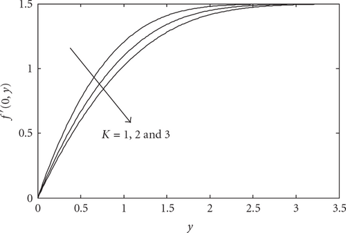
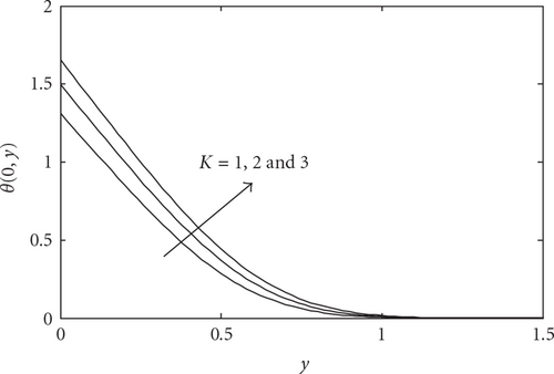
The velocity and temperature profiles near the lower stagnation point of the sphere, x ≈ 0, for various values of K with fixed Pr = 7 and λ = 1 are plotted in Figures 2 and 3, respectively. From these figures, it is shown that as K increases, the velocity profiles decrease and the temperature profiles increase.
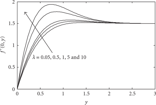
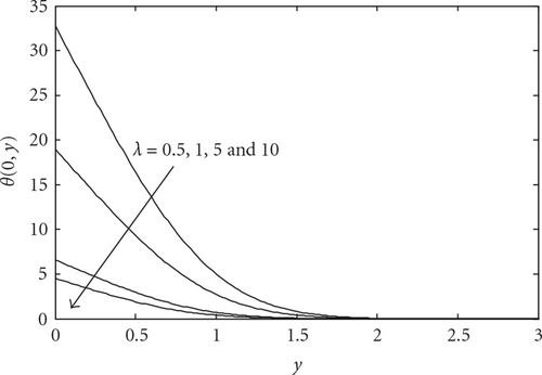
Figures 4 and 5 illustrate the velocity and temperature profiles near the lower stagnation point of the sphere, x ≈ 0, for various values of λ with fixed Pr = 1 and K = 1, respectively. We found that the velocity profiles increase while the temperature profiles decrease when the mixed convection parameter λ increases. Also, it is noticed that there are overshoots of the velocity profiles when λ > 1 where these overshoots take place higher for λ = 10 than for λ = 1.
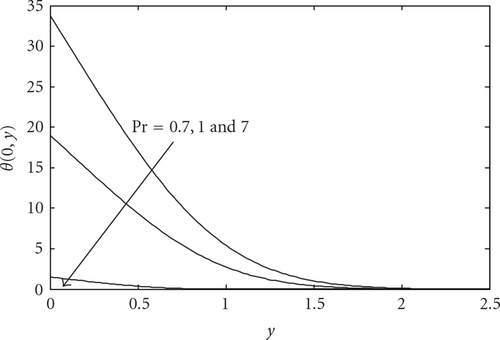
Figures 6 and 7 illustrate the velocity and temperature profiles near the lower stagnation point of the sphere, x ≈ 0, for various values of Pr with fixed K = 2 and λ = 1, respectively. It is seen that, as the Prandtl number Pr increases, both the velocity and temperature profiles decrease. At large Pr(≫1), the thermal boundary layer is thinner than at smaller Pr. This is because for small values of Pr (≪1), the fluid is highly conductive. Physically, if Pr increases, the thermal diffusivity decreases and this phenomena leads to the decreasing of energy ability that reduces the thermal boundary layer. It is also noticed that there are overshoots of the velocity profiles when Pr ≤ 1 where these overshoots are higher for Pr = 0.7 than for Pr = 1.

5. Conclusions
In this paper, we have numerically studied the problem of mixed convection boundary layer flow from a solid sphere in a micropolar fluid, generated by Newtonian heating. It is shown that the mixed convection or buoyancy parameter λ, the material or micropolar parameter K, and the Prandtl number Pr affect the flow and heat transfer characteristics. We can conclude that (for the case of NH):
- (i)
when Pr and K are fixed, an increase in parameter λ leads to the decrease of both the heat transfer coefficient −θ′(0) and the wall temperature θ(0);
- (ii)
when Pr and λ are fixed, an increase in parameter K leads to the decrease of the skin friction coefficient f′′(0) and the increase of the wall temperature θ(0);
- (iii)
when Pr and K are fixed, an increase in parameter λ leads to the increase of the skin friction coefficient f′′(0) and the decrease of the wall temperature θ(0);
- (iv)
when K and λ are fixed, an increase in parameter Pr leads to the decrease of the skin friction coefficient f′′(0) and the wall temperature θ(0);
- (v)
near the lower stagnation point of the sphere, the velocity profiles decrease while the temperature profiles increase when the parameter K increases;
- (vi)
near the lower stagnation point of the sphere, the velocity profiles increase while the temperature profiles decrease when the parameter λ increases;
- (vii)
near the lower stagnation point of the sphere, both the velocity and temperature profiles decrease when the Prandtl number Pr increases.
Acknowledgment
The authors gratefully acknowledge the financial supports received from the Ministry of Higher Education, Malaysia (UKM-ST-07-FRGS0036-2009) and a research grant (RDU 090308) from the Universiti Malaysia Pahang.


