Pulsed Nd:YAG Laser Microtexturing AISI-O1 Surface for Thermal Spray Coating
Abstract
Pulsed Nd:YAG laser was used to microtexture AISI-O1 cold work steel to control the substrate surface characteristics for later thermal spray coating to enhance the wearability. Influence of microtexturing parameters on the 3D surface morphology was studied by Atomic Force Microscopy (AFM), Scanning Electron Microscopy (SEM), and Optical Microscopy (OM). Results show that when AISI-O1 specimens are irradiated with various parameters the morphology of AISI-O1 cold work steel is changed correspondingly. It demonstrates that for a given laser the influence of laser microtexturing parameters on the morphology of the machined surface could be established successfully attractive to the thermal spray world. In the meantime, the wearability and antifatigue of the succedent thermal spray coating are significantly increased with the appropriate microtextured surface.
1. Introduction
In recent years, microtechnology has become one of the key disciplines, having a significant effect on the development of new products and production technologies, as well as on the introduction of new methods for medical treatment and diagnostics. Moreover, due to the enormous potential for new applications, in future, microtechnology will increasingly affect our daily life with an impact, comparable to that of the industrial revolution in the 19th century, or the development of information technologies in the 20th century [1–4].
To date, a key issue associated with thermal spray coating is controlling the substrate characteristics, such as surface preparation. Therefore, knowledge of surface machining from the micrometer scale is of critical importance to future thermal spray technological growth. Consequently, the complicated problems due to micromachining should be overcome.
It is well known that laser has been widely used as a machine tool to modify the surface of the engineering materials, such as laser surface alloying, laser cladding, surface texturing, laser physical vapor deposition, and so forth, [2, 3, 5]. In recent years, laser micromachining is becoming an attractive new technique to polish diamond, lens, and so on [2–9].
By considering the unique characteristics of the laser radiation and excellent noncontact micromachining possibility with the laser, an attempt has been made to microtexture AISI-O1 employing the concepts of microprocessing in this research to overcome current problems in the thermal spray technology.
2. Experimental Material and Procedures
2.1. Experimental Material
The chemical composition of AISI-O1 is shown in Table 1.
| Element | C | Si | Mn | Cr | W | V | Fe |
|---|---|---|---|---|---|---|---|
| (wt.%) | 0.9 | 0.3 | 1.2 | 0.5 | 0.5 | 0.1 | Bal. |
2.2. Experimental Procedures
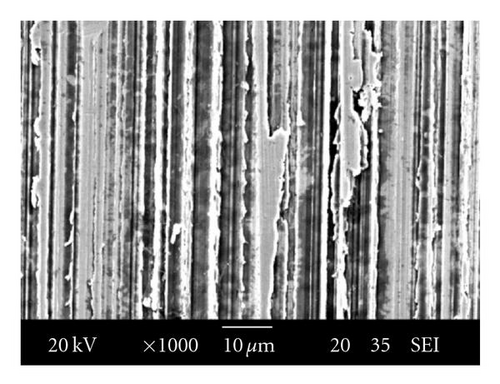
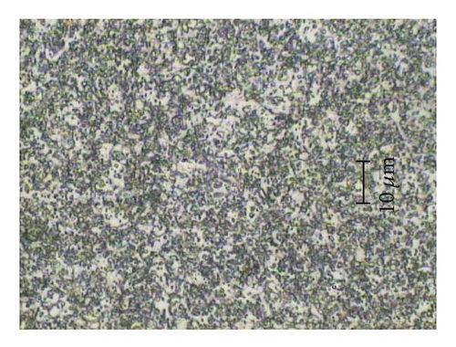
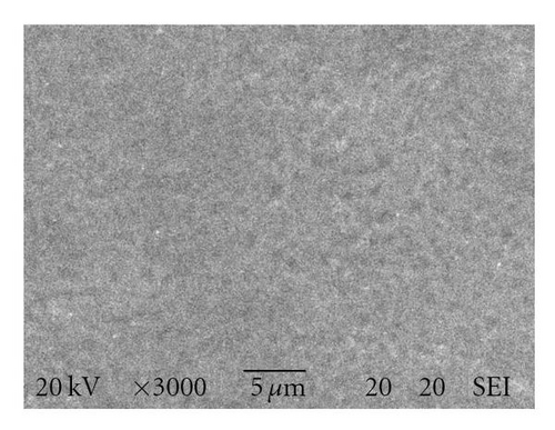
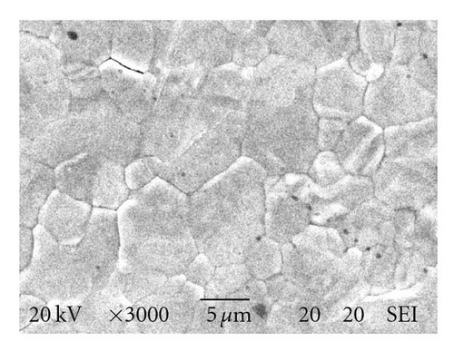
The materials were machined into 10 mm × 10 mm × 25 mm and carefully cleaned by acetone and pure ethyl alcohol to remove any contaminants on its surface. The initial morphology was shown in Figure 1. Figure 2 illustrated the microstructure of AISI-O1.
A GSI Lumonics Model JK702H pulsed Nd:YAG TEM00 mode laser system, with wavelength of 1.06 μm, defocused distance of 15 mm, and beam diameter of approximately 1.26 mm on sample, was used to irradiate the AISI-O1. The corresponding processing parameters are listed in Table 2.
| Processing parameters | Laser input energy | Feed rate | Pulse duration | Frequency |
| P (J) | v (mm/min) | PD (ms) | f (Hz) | |
| 1, 2, 3 | 100, 200, 300, 400 | 2, 3, 4 | 15, 20, 25, 30 |
After processed, the surface morphology was observed by Atomic Force Microscopy (AFM), Scanning Electron Microscopy (SEM) JEOL/JSM-5600 and Optical Microscopy (OM).
3. Results and Discussion
3.1. Morphology of Laser Microtexturing AISI-O1 Surface
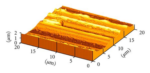
The initial microtexture of AISI-O1 measured by AFM is shown in Figure 3. It shows that a lot of debris/scraps distribute on the surface. Also, ridges and grooves before laser processing are obviously observed.
According to onset of laser processing temperature [8–11], the texture of the laser irradiated surface will be changed with the various laser input energy (such as laser power (P), feed rate (v), pulse duration (PD), and frequency (f)). Figure 4 shows the three-dimensional morphologies of the laser microtextured surface with various input energy measured by AFM.
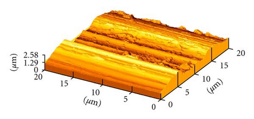
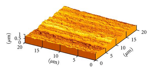
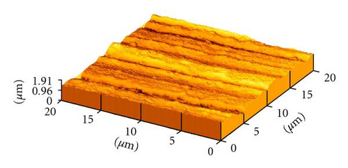
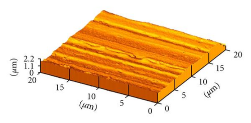
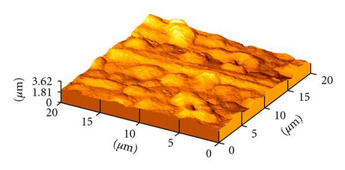
It shows that when the input energy is lower the effect of laser processing parameters on the morphology of AISI-O1 is not distinct, as shown in Figure 4(a). Only little surface area is melted slightly. Moreover, ridges/grooves and debris are still detected evidently. With the increase of input energy, there are large amount of micropits distributed on the microtextured surface (Figure 4(b)). In addition, it is well known that the morphology of microtextured surface relies on the removal of surface material by melting and evaporation, and its subsequent resolidification. Due to lower input energy effecting on substrate, the influence of laser microtexturing during this procedure will be mainly relied on melting the base metal locally in the microscale on the basis of the substrate surface profile. When the AISI-O1 surface is processed with higher input energy than that of conditions in Figure 4(b), the morphology of the AISI-O1 will be changed correspondingly as shown in Figure 4(c). Compared with Figure 4(b), the micropits are almost melted and the surface is processed little more smoothly. The influence of laser microtexturing at the moment will be a combination of the base metal melting and vaporizing, which is dominant factor relying on the input energy. With the input energy increasing higher, the morphology of laser processing will lie on the metal melting shown in Figure 4(d). It can be found that the surface is covered by melted metal with smoother texture. But, if the input energy is increased further, the metal melting will coexist with the metal vaporizing in the laser processing procedure. Figure 4(e) shows that with the further increasing of the input energy the surface of AISI-O1 will be processed seriously with lots of cracks, craters, and protuberances distributed on the surface resulting in coarser surface textutre and leading to the poor properties of surface. Finally the laser microtexturing on the surface does not have any meaning on such scale as shown in Figure 4(e). It illustrates that the surface of AISI-O1 will be processed with various morphologies successfully under the controlled laser input energy.
3.2. Texture of Laser Microtexturing AISI-O1 Surface
Generally, increase in input energy simultaneously raised up the heat input to the surface substrate. Too high energy is likely to melt the surface of substrate which subsequently changes the surface morphology and mechanical properties of the AISI-O1 specimens resulting in the failure of laser microtexturing. Compared with the originally machined surface (Figure 1), the processed surface (Figure 5(a)) shows the smoother surface, and micropits scatter over on the surface; cf., Figures 4(b) and 5(a). Such surface morphology with scattering of micropits features (Figure 5(a)) implies that there is some level of change of properties of AISI-O1 surface. With pulse energy increasing further, the irradiated surface will be relatively more melted and resolidification is observed; cf., Figures 4(e) and 5(b). Furthermore, due to higher input energy into the substrate, during resolidifying the melt and subsequent shrinkage, it leads to lots of cracks scattered on the irradiated surface. Obviously, the properties of the initial surface are changed to some degree (Figure 5(b)), and the laser microtexturing on AISI-O1 surface for coating later does not have the significance to some extent.
3.3. Microstructure of Laser Microtexturing
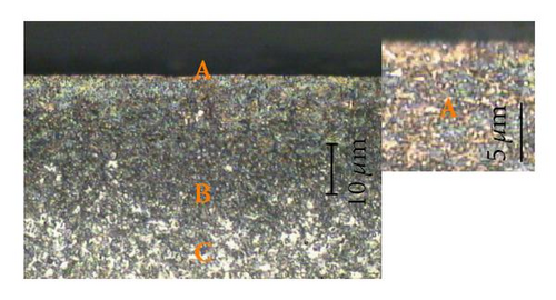
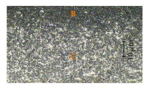
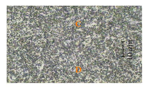
The cross-section micrograph of laser microtextured specimen with the processing parameters same in Figure 4(b) is shown in Figure 6. The alteration can be observed obviously. The processed surface that is significantly improved by laser resulted in smoother surface with microstructure changed as shown in Figure 6(a) labeled as A zone. The zone A has been known to be a hardened layer with some of the spheroidized carbide particles largened to some extent (Figure 6(a)). As zone B, finer spheroidized carbide particles disperse in the matrix of ferrite resulting in improving the higher properties of mold applications (cf., Figures 6(a) and 6(b)). It is well known the zone C is the heat affect zone (HAZ) as shown in Figures 6(b) and 6(c). The zone D is the microstructure of AISI-O1, cf., Figures 1 and 6(c). Contrasted zone C with zone D, it illuminates that the microstructure of zone C is nearly as same as zone D; it indicates that the input energy into the base metal is too low to affect the mechanical properties of AISI-O1 to large scale during the laser microtexturing. According to Figure 6(a), it depicts the average thickness of the zone A and B is approximately 40 μm, whereas the average thickness of the zone A is about 10 μm.
3.4. Practical Application
3.4.1. Wear Test
Wear was studied using a Cameron-Plint TE67 wear test rig (Made in UK) under dry conditions with a sliding speed 1.34 m/s at constant applied loading of 36.7135 N. The stroke was set to 400, 600, and 1600 mm, respectively.
Ultrasonic cleaner with 28 ~ 34 Hz frequency was used for cleaning samples. EIS-200ER plasma thermal spray system made by Elionix, with accelerated voltage 2500 V, Ar gas flow rate 0.61 SCCM, current 16 ~ 20 mA and focus spot diameter of approximately 8 mm, was used to coat WC/NiCrSi on the AIS-O1 surface. All well-coated samples were ultrasonically cleaned in an acetone bath for 2 minutes and carefully dried before/after wear testing. The weight of samples was measured by the Sartorius electronic weight before and after the wear testing with a minimum accuracy of 0.0001 g. The results are listed in Table 3 and plotted in Figure 7. The corresponding coating thickness is expressed in Table 4. Generally speaking, the wear loss of coating with laser microtexturing is lower than that without coating. However, when the thickness of coating thickened, the wear loss will be increased further, especially for the thicker thickness as shown in Figure 7 line D resulting in the lower quality coating.
| Sample | Load | Sliding distance | Initial weight | Finished weight | Lost weight |
|---|---|---|---|---|---|
| (N) | (mm) | (g) | (g) | (g) | |
| A | 36.7135 | 400 | 6.0694 | 6.0684 | 0.0010 |
| 600 | 5.7536 | 5.7523 | 0.0013 | ||
| 1600 | 5.5323 | 5.5304 | 0.0019 | ||
| B | 36.7135 | 400 | 6.5421 | 6.5413 | 0.0008 |
| 600 | 6.2667 | 6.2657 | 0.0010 | ||
| 1600 | 6.0356 | 6.0343 | 0.0013 | ||
| B* | 36.7135 | 400 | 5.9155 | 5.9142 | 0.0013 |
| 600 | 5.6722 | 5.6704 | 0.0018 | ||
| 1600 | 5.2968 | 5.2945 | 0.0023 | ||
| C | 36.7135 | 400 | 5.7397 | 5.7388 | 0.0009 |
| 600 | 5.2394 | 5.2383 | 0.0011 | ||
| 1600 | 6.0682 | 6.0667 | 0.0015 | ||
| D | 36.7135 | 400 | 5.5043 | 5.5033 | 0.0010 |
| 600 | 6.3472 | 6.3457 | 0.0015 | ||
| 1600 | 6.5172 | 6.5153 | 0.0019 | ||
- *Without laser microtexturing on the surface.
| Sample | A | B | B* | C | D |
|---|---|---|---|---|---|
| Precoating | Non | 0.3 mm | 0.3 mm | 0.5 mm | 1 mm |
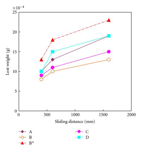
Also, the antiwear quality of the coating with laser microtexturing at the thickness of 0.3 mm (line B) and 0.5 mm (line C) is better than that without coating (line A) in all three sliding cases. Furthermore, the wear loss of samples without laser microtexturing (line B*) is higher than that of without coating as initial condition and coating with microtexturing both. It demonstrates that because of the laser microtexturing on the surface the coating will be bonded with the substrate more effectively. As for the coating without laser microtexturing, in addition to ridges and grooves, there are still a lot of particles/debris distributed on the surface even though after being carefully cleaned by acetone and pure ethyl alcohol as shown in Figures 1 and 3. Therefore the strength between the coating and substrate will be decreased obviously resulting in the lower antiwear quality as shown in Figure 7 line B*.
3.4.2. Fatigue Test
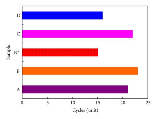
The fatigue test was also carried on the Cameron-Plint TE67 wear test rig, where the maximum heating temperature was 800°C with 2 minutes preservation, and the heating speed was 20°C/min. Subsequently, samples were put into the 25°C water. After cooling, samples were cleaned by acetone and alcohol and dried by the drier. Finally, samples were observed by optical microscopy. The results are listed in Table 5, and its corresponding bar type chart is shown in Figure 8. It shows that with the laser microtextured surface the fatigue properties of spray coating are increased to some extent, especially for the coating with 0.3 ~ 0.5 mm thickness. But, for spray coating with 1 mm thickness, the quality is decreased even lower than that of wear test listed in Table 3. However, for the coating on the surface without laser microtexturing, the quality of surface related to fatigue has not been improved essentially with the easily peeled off coating at the lowest cycles as shown in Figure 8 (bar B*).
| Sample | Cycles (1 unit = 200 cycles) | |||||||||||||||
|---|---|---|---|---|---|---|---|---|---|---|---|---|---|---|---|---|
| 1 | 2 | 3 | 4 | 5 | …… | 15 | 16 | 17 | 18 | 19 | 20 | 21 | 22 | 23 | 24 | |
| A | + | + | + | + | + | …… | + | + | + | + | + | + | + | − | ||
| B | + | + | + | + | + | …… | + | + | + | + | + | + | + | + | + | − |
| B* | + | + | + | + | + | …… | + | − | ||||||||
| C | + | + | + | + | + | …… | + | + | + | + | + | + | + | + | − | |
| D | + | + | + | + | + | …… | + | + | − | |||||||
4. Conclusion
Microsurface texturing of AISI-O1 is attained irradiated by pulsed Nd:YAG laser with various microprocessing parameters. Studied by Atomic Force Microscopy (AFM), Scanning Electron Microscopy (SEM), and Optical Microscopy (OM), it shows that the wearability and antifatigue of AISI-O1 with the thermal spray coating are significantly increased with the appropriate microtextured surface.
Acknowledgment
The work described in this paper was supported by a grant from City University of Hong Kong (no. SRG7002236).


