Torsion Effect and Suppression Scheme of a Translation–Tilt Compensation Pendulum for Accelerometer Performance Investigation
Abstract
Seismic noise is a major limitation for high-precision electrostatic accelerometer performance investigation on the ground. Various pendulums were developed to isolate the seismic noise, and the translation–tilt compensation pendulum is a new low-frequency passive horizontal vibration isolation pendulum. But the test level of the accelerometers mounted on the pendulum bench is influenced by the cross-coupling from the rotational axis of the bench. In this study, we discuss the influence of the torsional behavior of the translation–tilt compensation pendulum in depth and propose a suppression scheme based on a novel “four-wire” suspension structure. An experimental platform was developed to validate the theoretical analysis and examine the vibration isolation performance. The results show that the acceleration noise of the pendulum with “four-wire” suspension structure reached 2 × 10⁻⁹m/s2/Hz1/2 around 0.1 Hz which is usually the working frequency band of the accelerometer. This result is two orders of magnitude lower than the previous noise level. The seismic noise suppression of the translation–tilt compensation pendulum is improved, and the frequency band of vibration isolation is expanded. The pendulum can be applied in more precise experiments that are required to suppress seismic noise.
1. Introduction
Seismic vibration isolation is a focus of attention in many fields, such as the safety of ground-based infrastructures [1–3], ground-based gravity wave detectors [4–6], and other precision experiments and precision manufacturing [7–9]. For ground-based gravity wave detectors, seismic disturbance is the dominant disturbance among all environmental disturbances at low frequencies. Therefore, the detectors have stringent requirements in terms of vibration isolation [10]. To avoid the impact of seismic vibrations, many precision experiments have focused on the spatial environment. Spaceborne gravitational wave detection missions such as LISA [11], TianQin [12], and TaiJi [13] have successfully launched their own exploration satellites, which have a lower measurement frequency band and higher resolution. As the key payload of those satellites, electrostatic accelerometer plays an important role in the space science mission. In the satellite gravity measurement mission, electrostatic accelerometer also serves as the core payload due to its high resolution and limited measurement range. However, the lack of performance detection and evaluation methods directly hinders the advancement and practical application of space electrostatic accelerometers [14]. Especially, the accelerometer performance investigation is still affected by the environmental noise on the ground. The extremely high resolution and narrow dynamic range of accelerometers make seismic noise the dominant limitation in ground-based studies [15–17].
The investigation of the accelerometer is inevitably affected by seismic waves on the ground, so the vibration isolation bench must be studied. The electrostatic accelerometer’s low measurement bandwidth, usually approximately 0.1 Hz, makes it difficult for many vibration isolation systems to function properly at such low frequencies [18–20]. The translation–tilt compensation pendulum is a potential solution for seismic noise suppression in the low-frequency band, and the seismic noise can be attenuated by more than 40 dB below 0.1 Hz on this pendulum bench [21]. Subsequently, a vibration isolation pendulum bench based on the translation–tilt compensation principle was established for accelerometer performance investigation and the experimental results demonstrated that the translation–tilt compensation pendulum can isolate seismic noise in a broad frequency range [22]. However, the translation–tilt compensation pendulum can only suppress the seismic motion in the translational direction, whereas the torsional motion is usually coupled to the translational direction to generate the torsion–translation coupling noise (i.e., the torsional effect). Therefore, the torsional behavior of the translation–tilt compensation pendulum should be studied further.
The study of the structural torsion effect has been conducted by many researchers, but mainly in the field of civil architecture [23–25]. Few studies have been conducted on the torsional effect of the vibration isolation pendulum for accelerometer performance investigations. According to previous research, the torsional effect can be suppressed by tuning the position of an electrostatic accelerometer in a translation–tilt compensation pendulum [26]. However, obtaining an optimum location is always difficult or impossible. Further investigation is warranted into additional factors affecting torsional effects and strategies for their suppression. To bridge this research gap, our study conducts a comprehensive torsion analysis of translation–tilt compensation pendulums and introduces a “four-wire” suspension scheme for torsional suppression. Finally, experimental validation of the “four-wire” suspension scheme confirms the theoretical analysis.
2. Torsion Effect
2.1. The Six-Degree-of-Freedom Model of the Accelerometer
The electrostatic accelerometer can simultaneously realize acceleration measurement with six degrees of freedom at the same time. Its basic principle is that the relative position and attitude of the test mass (TM) between the frames of the capacitor plates can be obtained by combining the capacitance changes between the capacitor plates around the TM. Then, the TM is controlled at the center of the frame of the capacitor plate by applying the corresponding control voltage on the different capacitor plates. Finally, the acceleration in the direction of each degree of freedom of the TM was inverted by the applied control voltage.
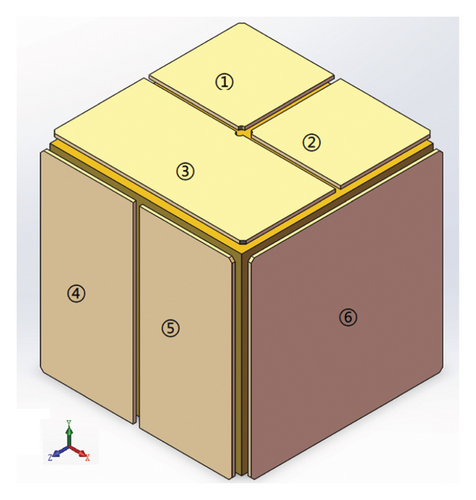
The structures of the TM and frame of the capacitor plates are shown in Figure 1. The capacitive plate frame was composed of six pairs of capacitive plates, and the motion of six degrees of freedom of the TM was measured by six pairs of capacitive plates. No. 1, No. 2, and No. 3 capacitor plates are used to measure the horizontal acceleration along the Y-axis and the rotational acceleration around the Z-axis and X-axis. No. 4 and No. 5 capacitor plates are used to measure the horizontal acceleration along the Z-axis and the rotational acceleration around the Y-axis. No. 6 capacitor plate is used to measure the horizontal acceleration along the X-axis. So, the TM was sensitive not only to translational motion but also to torsional motion.
2.2. Pendulum Motion Model
In our previous research, it was found that the accelerometer placed on the pendulum based on translation–tilt compensation concept is insensitive to the low-frequency horizontal vibrations, but it is sensitive to the torsional motion of the bench [26]. So, a typical pendulum bench is proposed to study the cross-coupling noise from the rotational axis of the bench. A simplified model of the translation–tilt compensation pendulum consists of a bench and a two-dimensional flexible flexure, and the pendulum bench is suspended by the flexure to ensure that the pendulum bench can swing around suspension point along the horizontal direction. An accelerometer was mounted on the pendulum bench, and it was simplified to a simple pendulum. The TM of the accelerometer was suspended in the center of the accelerometer, surrounded by electrodes, as shown in Figure 2(a). The small yellow square and yellow strips represent the TM and the electrodes, respectively. The horizontal vibration acceleration caused the horizontal movement of the suspension point, which drove the bench to move and tilt toward the direction of the vibration acceleration. The inertial force on the TM is opposite to the component of the gravitational force along the bench surface direction owing to the tilt of the bench. As a result, the accelerometer on the pendulum bench is insensitive to horizontal vibration acceleration, which explained by the translation–tilt compensation principle.
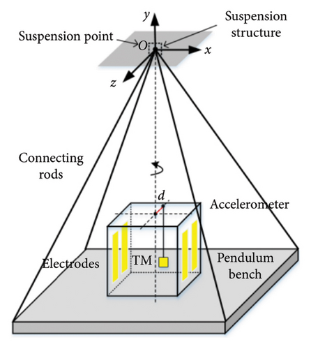
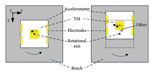
In the following joint experiment of accelerometer and pendulum bench, we found that the TM of the accelerometer is subjected not only to horizontal accelerations but also to rotational accelerations on the pendulum bench. The location of the TM of the accelerometer is inevitably subject to an offset in the z-axis owing to installation errors, and this is the main reason of the cross-coupling noise. The offset is expressed in terms of d as shown in Figure 2, which is the three-dimensional diagram of the translation–tilt compensation pendulum. Figure 2(b) shows the top view diagram of the translation–tilt compensation pendulum. When TM is right on the rotational axis of the pendulum bench as shown in the left figure of Figure 2(b), the electrodes and the TM of the accelerometer would be subjected to a rotational acceleration due to the torsional motion of the pendulum bench. As shown in the right figure of Figure 2(b), the rotational acceleration of the bench makes the TM of the accelerometer subject to a horizontal acceleration along the tangent direction owing to the offset d. The rotational acceleration of the bench is coupled to the horizontal acceleration of the accelerometer. Then the cross-coupling noise is generated which affected the accelerometer performance investigation on the ground.
Interpretation of the notation in equations (1) and (2) is summarized in Table 1.
| Parameter | Interpretation |
|---|---|
| M | System mass (excluding the mass of TM) |
| m | Mass of TM |
| L | Distance between CoM and suspension point O |
| L0 | Distance between the TM and its suspension point |
| h | Distance from CoM to TM |
| d | TM offset |
| Iy | System MoI around y axis at suspension point |
| IZ | Bench MoI around z axis at suspension point |
| IZ0 | Bench MoI (moment of inertia) around z axis at its CoM |
| kb | Bending stiffness of the flexure |
| ktwist | Twist stiffness of the bench |
| γ | Damping coefficient of the bench |
| γ0 | Damping coefficient of the TM |
According to term A, the cross-coupling noise disappears when offset d is exactly equal to zero. In fact, it is difficult to set the TM of the accelerometer at the center axis of the bench. In addition to the installation error of the pendulum bench, the TM of the accelerometer will not be in the center of the accelerometer because of its own installation error. In addition to the offset, the cross-coupling noise is related to the bending stiffness kb of the flexure and the twist stiffness ktwist of the bench. So, the effects of the bending stiffness kb and twist stiffness ktwist on the vibration isolation performance of the pendulum bench are worth investigating.
2.3. Analysis of the Cross-Coupled Noise
This indicates that the performance of low-frequency vibration isolation is determined by the bending stiffness kb. The amplitude–frequency curves of H1(s) for different values of kb are shown in Figure 3.
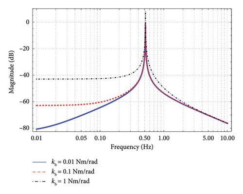
As shown in Figure 3, the vibration isolation ratio of the pendulum increases with a decrease in the bending stiffness kb in the low-frequency band (below 0.5 Hz of a swing resonance frequency).
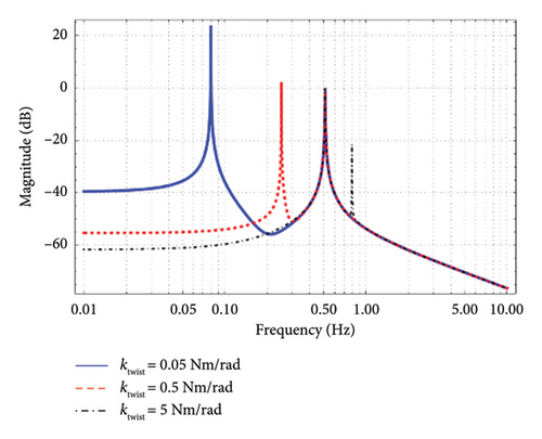
This shows that, in addition to kb and d, the twist stiffness ktwist also affects the vibration isolation ability. Figure 4 shows the amplitude–frequency curves of the pendulum with different ktwist values. The peaks around 0.08, 0.25, and 0.8 Hz are the resonant frequencies of the twist mode corresponding to three different ktwist values. It can be observed that the greater the twist stiffness, the higher the twist resonance frequency, and the better the vibration isolation performance of the pendulum.
3. Design of the Suspension Flexure
Based on the above theoretical analysis, the vibration isolation performance of the pendulum can be improved by properly designing the bending stiffness of the suspension flexure and twist stiffness of the pendulum. However, to ensure the structural stability of the suspension flexure, the bending stiffness of the flexure must satisfy a certain strength design criterion.
3.1. 2D Flexural Suspension Scheme
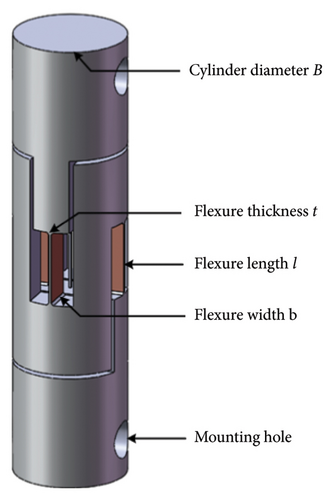
To this end, a two-dimensional flexural suspension structure made of a beryllium bronze bar is proposed in this study, as shown in Figure 5. There was a pair of flexures in both the horizontal and orthogonal directions to guarantee that the pendulum bench could swing freely in the horizontal and orthogonal directions.
3.2. “Four-Wire” Suspension Scheme
Therefore, a new type of a “four-wire” suspension scheme is proposed in this study, which can increase the value of B without changing the size of the suspension flexure, to improve the twist stiffness of the pendulum.
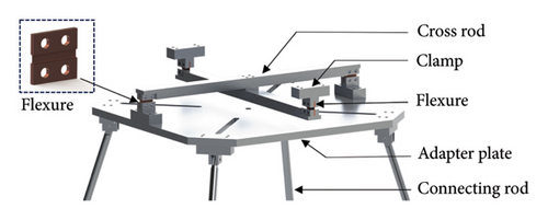
The three-dimensional structural model of the “four-wire” suspension scheme is shown in Figure 6. The suspension structure is composed of two pairs of independent flexures arranged in the horizontal and orthogonal directions. One pair in the horizontal direction was fixed directly on the top surface of the frame through a pair of clamps, and the other pair in the orthogonal direction was fixed on the adapter plate through another pair of clamps. Four aluminum alloy connecting rods secured the pendulum bench to the adapter plate. Two pairs of beryllium bronze flexures were mounted at identical heights via a cross-rod assembly, and one of them is enlarged in Figure 6. To ensure that the pendulum bench swings in two orthogonal directions, one pair of flexure is mounted in the horizontal direction and the other pair is mounted in the orthogonal direction. In this suspension scheme, the maximum span B of the suspension flexure was equal to the length of the cross rod. Hence, the maximum span B can easily be increased by increasing the length of the cross rod.
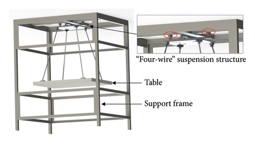
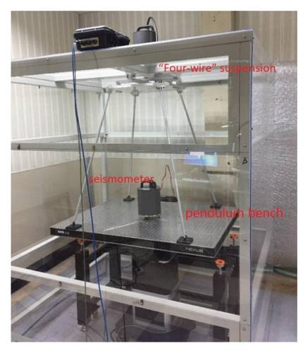
The pendulum bench with the “four-wire” suspension structure is shown in Figure 7. The main mechanical structure of the pendulum bench includes a rectangular table, the “four-wire” suspension structure, and an external support frame. The upper end of the suspension structure was mounted on top of the support frame through the pair of clamps which are circled in red in Figure 7, and the table was mounted under the “four-wire” suspension structure through four connecting rods.
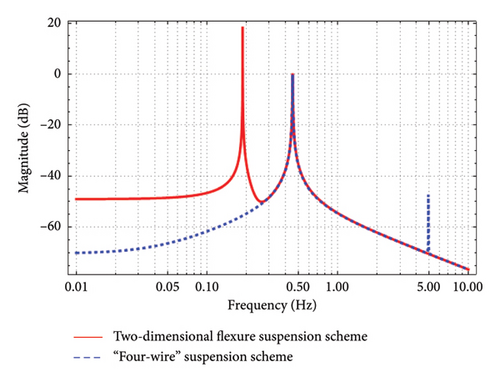
A commercial optical table was used as the pendulum bench. The table size was 900 × 1200 mm, thickness was 60 mm, and weight was 106 kg. To compare the performance of the “four-wire” suspension scheme, another pendulum bench equipped with a two-dimensional flexural suspension scheme was built, as shown in Figure 5. The parameter values of the two suspension schemes are listed in Table 2. Compared with the two-dimensional flexible suspension scheme, the twist stiffness of the pendulum bench with the “four-wire” suspension scheme increased by approximately 700 times, and the twist resonance frequency of the pendulum bench increases from 0.18 to 4.5 Hz.
| Parameter | 2D flexural suspension scheme | “Four-wire” suspension scheme |
|---|---|---|
| Flexure size (l, b, t) (mm) | 10 × 25 × 0.25 | 4 × 60 × 0.2 |
| Flexure max-span B (mm) | 30 | 500 |
| Flexure max-load (kN) | 7.5 | 14.40 |
| Twist stiffness | 30.27 Nm/rad | 20.94 kNm/rad |
| Twist resonance frequency (Hz) | 0.18 | 4.5 |
The theoretical transfer function curves of the pendulum bench with different suspension schemes are shown in Figure 8. As can be seen in Figure 8, compared with the two-dimensional flexural scheme, the twist resonance frequency of the pendulum with the “four-wire” suspension scheme increases from 0.18 to 4.5 Hz and the vibration isolation rate at 0.1 Hz increases from 47 to 62 dB. As a result, the vibration isolation performance of the “four-wire” suspension is much better than that of two-dimensional flexural schemes.
4. Experiment Results
A translation–tilt compensation pendulum with the “four-wire” suspension scheme was built for accelerometer performance evaluation. As shown in Figure 9, the pendulum bench was suspended in a closed steel frame of 1700 × 1400 × 2000 mm. A triaxial broadband seismometer (CMG-3ESPC) was fixed at the center of the bench to measure vibration noise. The experiment was conducted in a cave lab, where the temperature was stable and the temperature fluctuation was less than 40 mK/h.
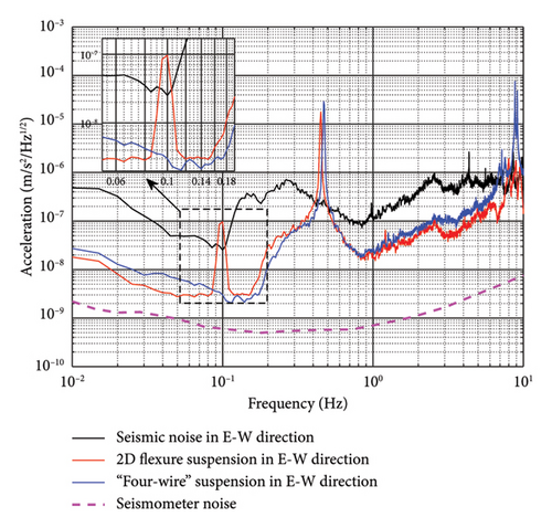
The measurement results of the acceleration noise of the pendulum bench and seismic noise along the east–west direction are shown in Figure 10. As can be seen from Figure 10, both of the two suspension schemes have a same swing resonance frequency of 0.45 Hz. However, the twist resonance frequency of the two-dimensional flexural suspension scheme is 0.1 Hz, which is exactly within the working frequency band of the electrostatic accelerometers which are widely used in the satellite gravity gradiometry missions. The twist resonance frequency of the “four-wire” suspension is much higher than the working frequency band of the electrostatic accelerometer at approximately 9 Hz. The acceleration noise of the bench with the two-dimensional flexural suspension was 1 × 10⁻⁷m/s2/Hz1/2 at 0.1 Hz, while the acceleration noise suppressed by the “four-wire” suspension was 2 × 10⁻⁹m/s2/Hz1/2 at 0.1 Hz. The acceleration noise suppression is close to two orders of magnitude at 0.1 Hz. Compared with the seismic noise, the acceleration noise has been attenuated by more than 20 dB below 0.1 Hz.
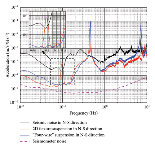
In the other direction of the horizontal orthogonality of the pendulum bench, we also carried out the experimental verification. Figure 11 shows the acceleration noise curves of the pendulum bench and seismic noise along the north–south direction. The results are similar to the measurement results in the east–west direction, and the torsional cross-coupling noise is also obviously suppressed. The twist resonance frequency was increased to 7 Hz, which is slightly below the twist resonance frequency in east–west direction. This is due to the difference in the structure of the two orthogonal directions of the pendulum bench.
5. Discussion and Conclusion
Electrostatic accelerometers play important roles in space missions because of their high precision and simultaneous measurement of six degrees of freedom. Meanwhile, this brings many difficulties and challenges to the research of accelerometers on the ground. It includes challenges of ground research of accelerometer caused by seismic noise. Therefore, various vibration isolation pendulums have been widely studied for accelerometer performance investigations on the ground.
In this study, the torsional motion coupling noise of a pendulum bench based on the translation–tilt compensation principle was investigated on the ground. A “four-wire” suspension scheme is developed to suppress the cross-coupling noise. The pendulum bench with the “four-wire” suspension has been manufactured, and the experiment validation has been carried out. The analysis results demonstrate that the twist resonance frequency of the pendulum bench is effectively suppressed by the “four-wire” suspension scheme, and the acceleration noise of the bench reached 2 × 10⁻⁹m/s2/Hz1/2 at 0.1 Hz, which is one order of magnitude lower than the seismic noise level. The pendulum bench provides a lower noise environment for the electrostatic accelerometer performance investigation on the ground.
According to a preliminary analysis, the connection cable of the accelerometer limits the movement of the bench, which may affect the vibration isolation performance of the pendulum bench. In addition, the influence of environmental factors, such as air disturbances and temperature fluctuations, needs to be further investigated.
Conflicts of Interest
The authors declare no conflicts of interest.
Funding
This study was supported by the Key Scientific and Technological Projects of Henan Province, 242102220097, and the Innovation Research Team of Sci-Tech, Henan Province, 25IRTSTHN020.
Acknowledgments
The authors would like to thank the National Precise Gravity Measurement Facility (Huazhong University of Science and Technology, Wuhan 430074, P. R. China) for the experimental conditions.
Open Research
Data Availability Statement
The data that support the findings of this study are available from the corresponding author upon reasonable request.


