Design and Evaluation of Hybrid Drivetrain Damper Considering the Influence of Engine Misfire on Torsional Shock
Abstract
Engine misfire is an accidental failure mode in internal combustion vehicles that can lead to the malfunction of power transmission system components. However, previous studies on engine misfire have generally focused on the engine rather than the drivetrain. In this study, we established a simulation model of a hybrid drive system with multiple degrees of freedom to investigate the torsional shock characteristics of the engine under normal and engine misfire conditions. Factors such as the torsional stiffness, gear-pair meshing stiffness, and moments of inertia for the damper, generator, and drive motor were considered. The dual-mass flywheel (DMF) was subsequently applied in the drivetrain model, and its stiffness parameters were varied to optimize their effects on the torsional shock experienced by the power transmission system. According to the results, the first- and second-stage stiffnesses of the DMF were set as 5.1 and 15.0 Nm/deg, respectively. Finally, the performance of the designed DMF damper was evaluated through simulations and physical tests of the drivetrain. The engine at full load under normal and engine misfire conditions as well as under a steady-state load when generating power at the engine output was investigated. The simulation results indicated that the torsional shock on the power transmission system satisfied the design limit of 500 Nm with an angular acceleration below 500 rad/s2. The errors between the simulated and measured peak impact torques and resonance speeds under the misfire condition were approximately 15% and 5%, respectively.
1. Introduction
Engine misfire refers to the condition in which one or more cylinders of an engine operate inadequately or fail to operate altogether during the combustion process. It is a common engine issue that reduces functional capacity, degrades performance, destabilizes operation, and can cause overload and major failures under full-load conditions if not detected promptly [1]. Common factors contributing to engine misfire include ignition system failure, fuel injection system malfunction, inadequate air flow, mismatched fuel pressure, the presence of impurities or moisture in the fuel, and mechanical failures within the engine [2]. An engine misfire event generates a torsional shock, and if multiple misfires transpire in rapid succession, this torsional shock can be excited repeatedly within a short timeframe, leading to component failure. For instance, during an engine misfire, the flywheel of an extended-range engine is subjected to an excessive impact torque that can cause cracks to develop within [3]. Thus, ensuring the reliability of power transmission system components under engine misfire conditions represents a critical engineering challenge.
Engineers have directed considerable effort toward diagnosing engine misfires via techniques such as monitoring the fluctuations in oxygen sensor signals [4], measuring the angular velocity of the crankshaft [5, 6], analyzing surge sensor data [7], and assessing variations in engine speed [8]. Since 2012, researchers have employed artificial neural network algorithms to detect engine misfires [9–12], and since 2020, new techniques such as convolutional neural networks and transfer learning have been applied to diagnose misfires [13–16]. Technology for engine misfire diagnosis is rapidly maturing, and detection systems that immediately activate emergency protocols to minimize potential damage have been developed [17–19].
Research on the dynamic responses of the vehicle powertrain to engine misfire has primarily focused on engine components. For example, the engine crankshaft is subjected to periodic dynamic loads, and engine misfires can aggravate its torsional vibration. Mehrgou [20] conducted a complete engine dynamics simulation using the ADAMS/Engine multibody dynamics software package to investigate the effects of engine cranktrain dynamics on the valvetrain considering backlash in the gear train and a torsionally flexible camshaft. Solmaz and Karabulut [21] developed a kinematic mathematical model of a four-cylinder diesel engine to examine the effects of cyclic variations and misfire issues on the engine crankshaft speed. Hmida et al. [22] proposed a torsional model of a four-cylinder crankshaft excited by acyclic phenomena; the inertia and gas torque of each engine cylinder were taken as external forces, and the vibration responses of the crankshaft were computed to investigate the effects of misfires. Wu et al. [23] employed the lumped-mass method to model a crankshaft and derived its dynamic equations using Lagrange’s equation. The torsional vibration responses of a coupled engine crankshaft–gearbox system were investigated with consideration of misfiring and breathing slant cracks, and the natural frequencies of both healthy and cracked systems were analyzed.
However, there is limited research on the torsional shock applied to an integrated drivetrain system by engine misfire. Published work has primarily focused on drivetrain system matching under traditional working conditions and developing innovative damper designs. For example, Wakabayashi et al. [24] studied the torsional damping of diesel engines using a rubber damper pulley. Shangguan and Niu [25] designed a multielement rubber damper to control the torsional vibration of the engine crankshaft. Shu, Wang, and Liang [26] reported that the application of a variable torsional damper to the engine crankshaft limited torsional vibration. Haris et al. [27, 28] investigated the mitigation of torsional vibration in automotive drivetrains using absorbers featuring both smooth and nonsmooth nonlinear characteristics. Paillot et al. [29] demonstrated a novel hybrid self-supplied torsional vibration damper for the crankshaft. Ma, Du, and Chen [30] studied the attenuation of torsional vibration in a closed-loop engine crankshaft system using a tuned-mass damper and nonlinear energy sink under various operating conditions.
Researchers have also performed simulations and experiments to evaluate the effectiveness of driveline matching for reducing torsional vibration. Liu, Dai, and Mou [31] observed that the installation of a silicone oil damper in an engine reduced the primary resonant torsional vibration amplitude, the maximum tension stress in the crankshaft, and the amount of noise emitted by the front end of the engine. Wu and Wu [32] developed an innovative three-stage stiffness clutch damper that effectively mitigated severe driveline vibration and gear rattle phenomena. Yan et al. [33] developed a damper equipped with a torque limiter and conducted experiments to enhance the noise, vibration, and harshness performance of a hybrid powertrain. Yücean and Mugan [34] developed and implemented a model predictive controller for a novel active torsional vibration damper that provided variable inertia, stiffness rate, and damping rate parameters to minimize the transmission of torsional vibration to the vehicle power transmission system.
Hybrid transmission systems exhibit distinct dynamics from conventional powertrains. The hybrid drive system incorporates multiple power sources and features various modes of drive-mode switching. Researchers [35–37] have investigated the vibrations and shocks induced by these transitions, along with techniques for their suppression. This system consists of components such as motors, engines, and gear pairs and is characterized by a complex structure and diverse operational modes. Scholars [38–41] have explored system mode matching and gear modifications to address NVH issues such as gear whine. Additionally, the hybrid drive system includes parts with significant moments of inertia, such as motors. In a previous study [42], we examined the effects of sudden changes in road excitation on differential impact loads.
To reduce the noise and vibration, several methods can be used in transmission systems, such as the clutch torsional damper (CTD), single-mass flywheel (SMF), dual-mass flywheel (DMF), and centrifugal pendulum vibration absorber (CPVA). For hybrid drive systems, we mainly study an SMF with a slipping clutch and a DMF.
The CTD [43] primarily comprises a damping disc, a driven disc hub, a damping spring, and a friction plate. Because of spatial constraints within the clutch-driven disk assembly, the damper has a limited torsion angle, while exhibiting high torsional stiffness. Consequently, its vibration-damping performance is moderate, and it is best suited for low-torque engines. The SMF is mounted at the end of the engine crankshaft, serving to store and release energy primarily through its substantial inertia and thereby ensuring smooth and continuous operation of the engine. The SMF dampers designed for hybrid drive systems equipped with a slipping clutch effectively isolate vibrations by utilizing a conventional pressure spring, thus providing protection against peak torque conditions. The DMF divides the mass of a traditional flywheel into two distinct components: the first component is affixed to the crankshaft end of the engine, and the second component is located on the transmission side of the drivetrain. These two segments are connected as a cohesive assembly by a curved-spring shock absorber. The curved spring can be selected from either Circumferential Short Spring or Circumferential Spring configurations. Positioning the curved spring externally to the flywheel enhances both the spring space and relative torsion angle. The DMF [44, 45] exhibits exceptional vibration isolation characteristics and is well-suited for application within hybrid drive systems. The CPVA [43, 46] is a device that utilizes centrifugal force to mitigate vibrations. While the centrifugal pendulum DMF damper exhibits superior damping performance to traditional DMF systems, it incurs higher manufacturing costs. Given that the operational conditions of hybrid drive systems are relatively simple and their vibrational intensity is moderate. Taking into account both cost-effectiveness and performance objectives, there are limited applications of CPVA within hybrid drive systems; thus, CPVA is predominantly utilized in dual-clutch transmission.
As the application of torsional vibration damping to limit the torsional shock transmitted to hybrid drive systems has not been addressed in previous research, in this study, we established a simulation analysis model for a hybrid electric vehicle drive system. This model facilitates analysis of the effects of various engine conditions on torsional shock within the power transmission system and optimization of the damper design parameters. The designed damper was subsequently applied in simulations and physical experiments to evaluate its performance. Thus, the effects of engine misfire on a hybrid power transmission system were systematically investigated for the first time.
2. Target Hybrid Powertrain
The powertrain architecture of a hybrid engine-driven vehicle is schematically illustrated in Figure 1, and its three-dimensional structure is shown in Figure 2.
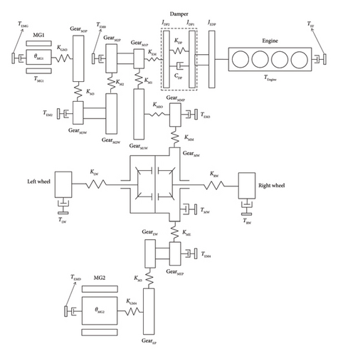
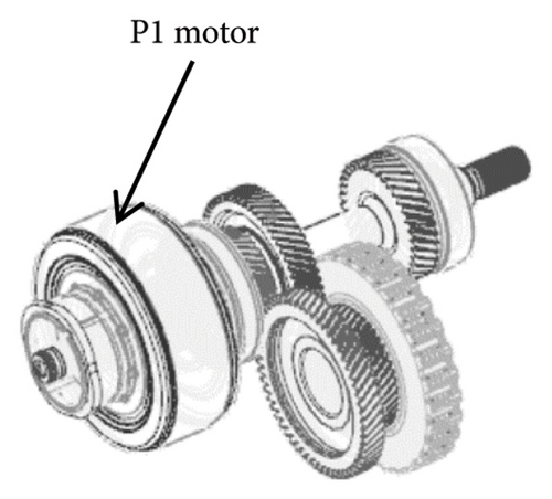
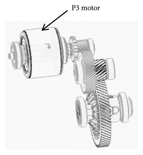
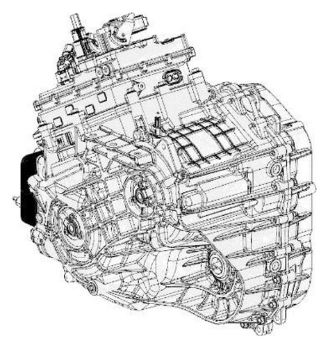
The considered powertrain consisted of an engine, damper, mechanical low (ML) pinion gear (GearM1P), ML wheel gear (GearM1W), mechanical high (MH) pinion gear (GearM2P), MH wheel gear (GearM2W), charge pinion gear (GearM3P), charge wheel gear (GearM3W), mechanical main pinion gear (GearMMP), mechanical main wheel gear and differential (GearMW), electrical pinion gear (GearEP), electrical wheel gear (GearEW), electrical main pinion gear (GearMEP), P1 motor at the engine output (MG1), P3 motor at the transmission output (MG2), left wheel, right wheel, and other components.
Hybrid vehicles can operate in the engine-driven mode, electric motor-driven mode, hybrid-driven mode (in which power from the engine and electric motor is combined), regen mode, engine initiated by the motor start mode, and charging mode. The power transmission pathways for these operational modes are presented in Table 1.
| Operating mode | Power input | Power transmission pathway | Power output |
|---|---|---|---|
| Engine-driven model in ML gear pair | Engine | Damper ⟶ GearM1P ⟶ GearM1W⟶GearMMP ⟶ GearMW |
|
| Engine-driven model in MH gear pair | Engine | Damper ⟶ GearM2P ⟶ GearM2W⟶GearMMP ⟶ GearMW |
|
| Electric motor-driven mode | P3 motor | GearEP ⟶ GearEW⟶GearMEP ⟶ GearMW |
|
| Hybrid-driven model in ML gear pair | Engine | Damper ⟶ GearM1P ⟶ GearM1W⟶GearMMP ⟶ GearMW |
|
| P3 motor | GearEP ⟶ GearEW⟶GearMEP ⟶ GearMW | ||
| Hybrid-driven model in MH gear pair | Engine | Damper ⟶ GearM2P ⟶ GearM2W⟶GearMMP ⟶ GearMW |
|
| P3 motor | GearEP ⟶ GearEW⟶GearMEP ⟶ GearMW | ||
| Regen model |
|
GearMW⟶GearMEP ⟶ GearEW ⟶ GearEP | P3 motor |
| Engine initiated by motor start mode | P1 motor | GearM3P ⟶ GearM3W⟶GearM2W ⟶ GearM2P ⟶ Damper | Engine |
| Charging model | Engine | Damper ⟶ GearM2P⟶GearM2W ⟶ GearM3W ⟶ GearM3P | P1 motor |
3. Powertrain Simulation Model
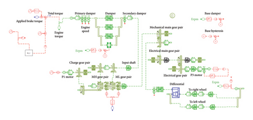
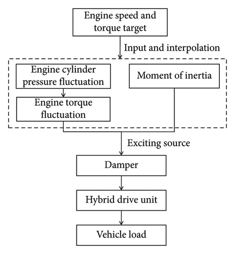
The Simcenter Amesim multidomain system analysis software was used to construct a dynamic simulation analysis model of the hybrid powertrain system described in Section 2, as shown in Figure 3, using the modeling logic presented in Figure 4.
Here, u denotes the specific internal energy; p denotes the pressure of the working medium within the cylinder; Vh denotes the working volume of the cylinder; QB denotes the heat released during fuel combustion in the cylinder; QW denotes the heat transfer through the cylinder walls; ms describes the quality of the air entering the cylinder; me describes the quality of the exhaust gas exiting the cylinder; hs and he denote the specific enthalpies at the inlet and exhaust valves, respectively; ε denotes the compression ratio; φ denotes the crankshaft angle; and λs denotes the connecting-rod crank ratio.
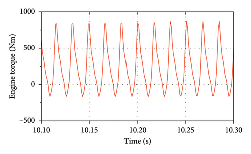
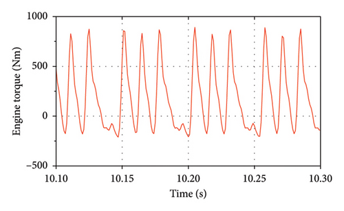
As the inertial forces must be included within the model, the engine torque information was derived as a function of the crankshaft angle across diverse speeds and torques for analyzing the impact transmitted to the hybrid drive system [48]. Figure 5(a) shows the fluctuation in the crankshaft torque during full-load operation under the normal engine driving condition, and Figure 5(b) shows the fluctuation in the crankshaft torque during full-load operation under the single-cylinder engine misfire condition. The engine undergoes four ignitions in 2 revolutions in the former case and undergoes three ignitions in 2 revolutions in the latter case.
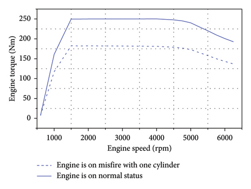
Furthermore, Figure 6 presents the engine torque under normal driving and single-cylinder misfire conditions during full-load engine operation. The peak torque of the engine reached 250 Nm in the former case and was reduced to 187.5 Nm in the latter case.
The influence of engine excitation on the hybrid power transmission system under misfire conditions must be assessed by computing the pertinent structural parameters of the system, which include the gear parameters, component moments of inertia, gear mesh stiffness, and shaft torsional rigidity.
The moment of inertia for each component of the power transmission system was measured using the three-dimensional Amesim model, and the results are presented in Table 2.
| Code | Component | Value | Unit |
|---|---|---|---|
| JEDP | Inertia moment of engine crankshaft | 0.0260 | kg·m2 |
| JDP1 | Inertia moment of primary flywheel | 0.1050 | kg·m2 |
| JDP2 | Inertia moment of second flywheel | 0.0050 | kg·m2 |
| JMIN | Inertia moment of mechanical input shaft | 0.0026 | kg·m2 |
| JM3W | Inertia moment of charge wheel gear | 0.0172 | kg·m2 |
| JM2W | Inertia moment of MH wheel gear | 0.0043 | kg·m2 |
| JM3P | Inertia moment of charge pinion gear | 0.0017 | kg·m2 |
| JMG1 | Inertia moment of generator rotor | 0.0175 | kg·m2 |
| JM1W | Inertia moment of ML wheel gear | 0.0059 | kg·m2 |
| JMMP | Inertia moment of mechanical output shaft | 0.0015 | kg·m2 |
| JMEP | Inertia moment of electric output shaft | 0.0008 | kg·m2 |
| JMW | Inertia moment of main driven gear and differential | 0.0480 | kg·m2 |
| JJEP | Inertia moment of motor input shaft | 0.0008 | kg·m2 |
| JMG2 | Inertia moment of drive motor rotor | 0.0298 | kg·m2 |
| JLW | Inertia moment of left wheel | 1.5364 | kg·m2 |
| JJRW | Inertia moment of right wheel | 1.5364 | kg·m2 |
| Code | Component | Value | Unit |
|---|---|---|---|
| KM1 | Mesh stiffness of ML gear pair | 4.06 × 10⁸ | N/m |
| KM2 | Mesh stiffness of MH gear pair | 3.93 × 10⁸ | N/m |
| KM3 | Mesh stiffness of charge gear pair | 3.19 × 10⁸ | N/m |
| KM5 | Mesh stiffness of electric gear pair | 5.02 × 10⁸ | N/m |
| KMM | Mesh stiffness of mechanical main gear pair | 5.53 × 10⁸ | N/m |
| KME | Mesh stiffness of electrical main gear pair | 5.53 × 10⁸ | N/m |
Finally, the dynamic torsional rigidity of the driveline shaft system was calculated using a finite-element model. The results are presented in Table 4.
| Code | Component | Value | Unit |
|---|---|---|---|
| KEM | Torsional stiffness of mechanical input shaft | 569 | Nm/deg |
| KGM3 | Torsional stiffness of P1 motor shaft | 600 | Nm/deg |
| KM1O | Torsional stiffness of mechanical output shaft | 3482 | Nm/deg |
| KGM4 | Torsional stiffness of P3 motor shaft | 686 | Nm/deg |
| KLW | Torsional stiffness of left axle | 109 | Nm/deg |
| KRW | Torsional stiffness of right axle | 74 | Nm/deg |
4. Evaluation of Torsional Dampers
As SMF and DMF torsional dampers, which possess single- and dual-stage torsional rigidities, respectively, are commonly used in hybrid drivetrains, we evaluated their effects on the torsional vibration of the modeled hybrid power transmission system. The parameters of these dampers are compared in Table 5.
| Type | SMF torsional damper | DMF torsional damper | |
|---|---|---|---|
| Illustration |  |
 |
|
| Primary damping parameters | Torsional stiffness (Nm/deg) | 13 | 5.1 |
| Torsion angle (deg) | ±25 | ±6.75 | |
| Secondary damping parameters | Torsional stiffness (Nm/deg) | N/A | 15.0 |
| Torsion angle (deg) | N/A | ±45 | |
| Maximum torsion angle (deg) | N/A | ±65 | |
| Hysteresis damping (Nm) | 15 Nm | 40 Nm–80 Nm | |
| Abuse torque (Nm) | 375–500 Nm | 500 Nm min | |
| Notes |
|
|
|
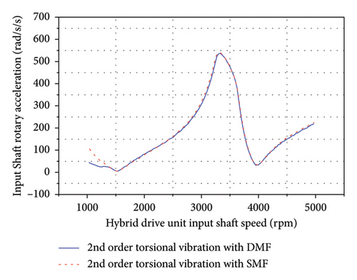
Considering that the engine adopts a four-cylinder configuration, it operates in one cycle with two cylinders engaged in work, and the main excitation of the engine is two-order. By conducting a fast Fourier transform analysis of the input-shaft speed fluctuations, we can derive the second-order angular acceleration to assess the vibration damping performance of various dampers.
As shown in Figure 7, when the engine drove the vehicle forward through the ML pinion–wheel gear pair at full load, the simulation results indicated that the maximum angular acceleration on the input shaft equipped with the SMF under the second-order torsional vibration was 540 rad/s2, as was that on the shaft equipped with the DMF under the same condition. Indeed, the damping performance of the SMF was generally comparable to that of the DMF, with the simulation results indicating that the input-shaft rotary accelerations of the SMF and DMF remained nearly identical over the range of 1500–5000 rpm.
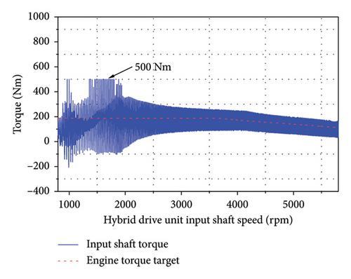
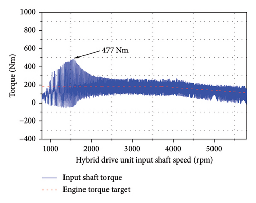
As shown in Figure 8, under the single-cylinder engine misfire condition, the peak transmission torque propelling the vehicle forward though the ML pinion–wheel gear pair was 187.5 Nm. Thus, the maximum impact torque on the power transmission system reached 1200 Nm when the SMF was used. However, the addition of a torque-limiting ring restricted the maximum impact to 500 Nm. Alternatively, when the DMF was used with properly designed first- and second-stage stiffnesses, the impact torque was limited to 477 Nm.
An SMF with a slipping clutch has been developed on the basis of the CTD, and this technology has been mastered by numerous local enterprises in China. In recent years, it has gained prominence with the advancement of new energy solutions, leading to an increase in its application. The DMF has been utilized within traditional drive systems, and although this technology presents certain complexities, it is more mature than the SMF and predominantly supplied by global vendors operating in China. Currently, the costs associated with the SMF with a slipping clutch and the DMF are comparable, with potential for the SMF with a slipping clutch to become more cost-effective in the future. The SMF with a slipping clutch has more parts and a more complex structure than the DMF; thus, the DMF is easier to assemble. In this study, we selected the DMF with consideration of the product robustness. As applications of the SMF with a slipping clutch continue to increase, it is expected that the DMF and SMF will develop together in the future. Vehicle manufacturers typically choose between the SMF with a slipping clutch and DMF according to their specific requirements.
In this study, we applied the DMF to the hybrid powertrain to evaluate the effects of the first- and second-stage DMF stiffnesses on the power transmission system using the 10 cases presented in Table 6.
| Case 1 | Case 2 | Case 3 | Case 4 | Case 5 | Case 6 | Case 7 | Case 8 | Case 9 | Case 10 | |
|---|---|---|---|---|---|---|---|---|---|---|
| First-stage stiffness (K1, Nm/deg) | 2.5 | 3.5 | 4.5 | 5.5 | 6.5 | 7.5 | 5.5 | 5.5 | 5.5 | 5.5 |
| Second-stage stiffness (K2, Nm/deg) | 10 | 10 | 10 | 10 | 10 | 10 | 7 | 15 | 20 | 25 |
In Cases 1–6, the second-stage stiffness was set as 10 Nm/deg to analyze the effects of different first-stage stiffnesses on the impact torque applied to the input shaft. The corresponding simulation results are presented in Figure 9.
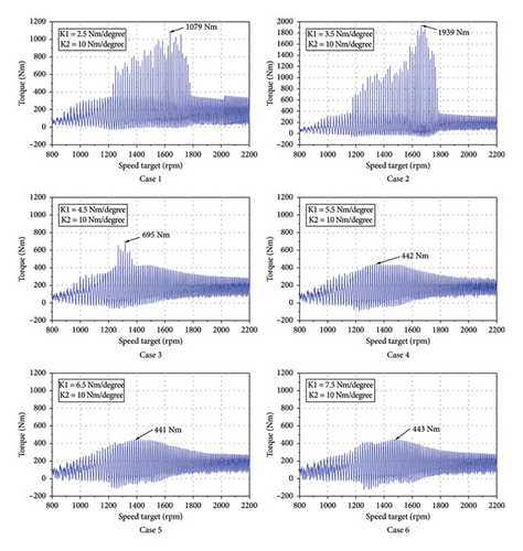
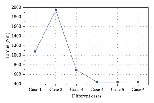
The maximum impact torques determined in Cases 1–6 are plotted in Figure 10. A lower first-stage stiffness clearly resulted in a larger impact torque, which reached a maximum of 1939 Nm. This is because the first-stage stiffness of the DMF was associated with torsion angles between −6.75 deg and −45 deg and between 6.75 deg and 45 deg, its second-stage stiffness was associated with torsion angles between −45 deg and −65 deg and between 45 and 65 deg, and when the torsion angle exceeded the second-stage limits—either falling below −65 deg or exceeding 65 deg—the spring was flattened into parallel circles, significantly increasing the contact stiffness. Thus, when the first-stage stiffness was low, the first-stage spring absorbed minimal impact torque energy, and the residual impact torque directly influenced the second-stage spring deformation. This resulted in a considerably higher impact torque when the first-stage stiffness was approximately one-third of the second-stage stiffness (Cases 1 and 2). In extreme cases where the torsion angle corresponding to this first-stage stiffness failed to effectively counteract the system impact torque, the second-stage spring engaged and rotated, thereby producing a more pronounced impact. Once the first-stage stiffness increased to 5.5 Nm/deg, the impact torque was limited to 500 Nm, with subsequent increases in the first-stage stiffness exhibiting no significant influence on the impact torque.
In Cases 4 and 7–10, the first-stage stiffness was set as 5.5 Nm/deg, and the effects of the second-stage stiffness on the impact torque were evaluated, as shown in Figure 11.
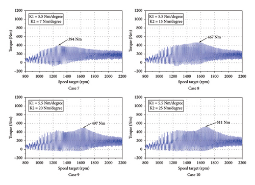
The maximum impact torques in Cases 4 and 7–10 are presented in Figure 12. For second-stage stiffness values of 7, 10, 15, 20, and 25 Nm/deg, the impact torque increased slightly with an increase in the stiffness, with minimum and maximum values of 400 and 530 Nm for stiffnesses of 7 and 25 Nm, respectively.
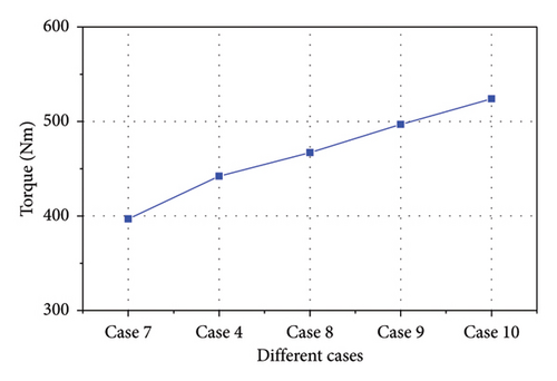
According to the analysis results, the optimal values for the DMF damper were determined to be a first-stage stiffness of 5.5 Nm/deg and a second-stage stiffness of 15.0 Nm/deg. In alignment with these stiffness targets, we engaged in discussions with the damper supplier, taking into account their specifications for the spring curvature radius and wire diameter, as well as the dimensions of the curved-spring cavity. We selected a spring stiffness parameter that was close to the development target and confirmed the vibration damping performance. After confirming that all requirements were met, the first and second stiffness parameters were locked. Finally, the hybrid power transmission system was designed to provide a first-stage stiffness of 5.1 Nm/deg and a second-stage stiffness of 15.0 Nm/deg.
The significant moment of inertia in the hybrid drive system is primarily attributed to the motor. However, under engine-driven conditions, the moment of inertia associated with components such as gears and shafts is relatively small, limiting its influence on the system’s impact load. Furthermore, the meshing stiffness of the gear is determined by its design parameters, which exhibit minimal variability in practical engineering applications; thus, this paper does not discuss the factors influencing these aspects.
5. Simulation and Experimental Verification of Torsional Damping
The optimal DMF damper parameters and structural characteristics of the hybrid power transmission system described in Sections 2 and 4 were applied in the simulation model to evaluate the impact torque and verify the robustness of the damper design. Evaluations were conducted when driving the ML pinion–wheel gear pair with the engine at full load under normal and engine misfire conditions and generating electricity using the P1 motor with steady-state engine conditions under normal conditions. The simulation and experimental verification of the torsional damping logic is presented in Figure 13.
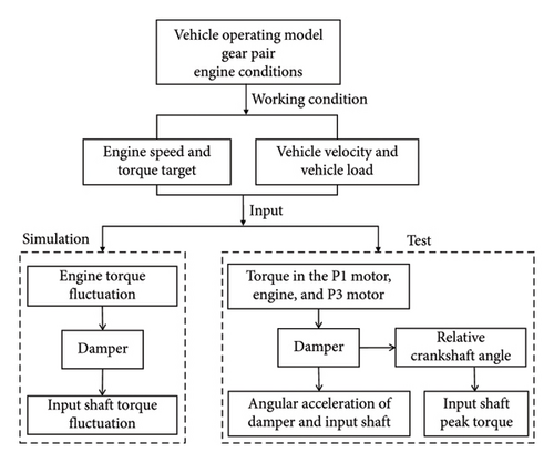
The maximum transmission torque of the hybrid drivetrain was set as 250 Nm, and the impact torque was designed to remain below twice this value, corresponding to a threshold of 500 Nm. Furthermore, the angular acceleration of the mechanical input shaft was limited to 500–600 rad/s2 to mitigate gear rattle.
5.1. ML Pinion–Wheel Gear Pair Driven by Engine at Full Load Under Normal Conditions
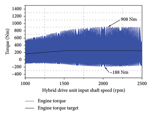
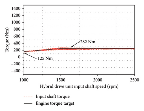
A vehicle velocity of 30–60 km/h was applied with the ML pinion–wheel gear pair driven by the engine at full load under normal conditions. A peak torque output of 250 Nm was targeted as the rotational speed of the engine increased from 1200 to 2400 rpm. As indicated by the simulation results in Figure 14, the engine output torque varied between −188 and 908 Nm while the input shaft torque fluctuated from 125 to 282 Nm, suggesting that the DMF damper exerted a significant vibration isolation effect.
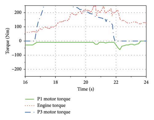
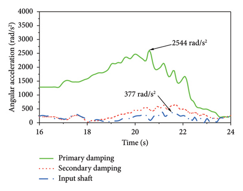
Next, the angular accelerations of the vehicle components were determined when the ML pinion–wheel gear pair was driven by the engine at full load under normal conditions for 16.8–21.2 s as the speed increased from 20 to 90 km/h and the generator produced power. As shown in Figure 15, the engine torque reached 250 Nm, the primary angular acceleration of the damper was 2544 rad/s2, and the dampened angular acceleration of the input shaft was 377 rad/s2, which was below the threshold of 500 rad/s2 for effective internal control.
5.2. ML Pinion–Wheel Gear Pair Driven by Engine at Full Load Under Single-Cylinder Misfire Condition
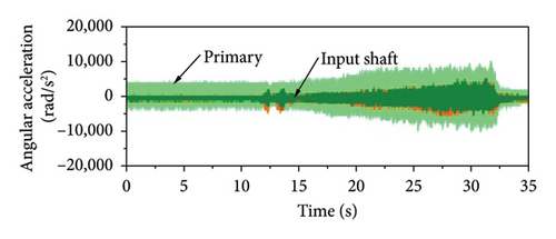
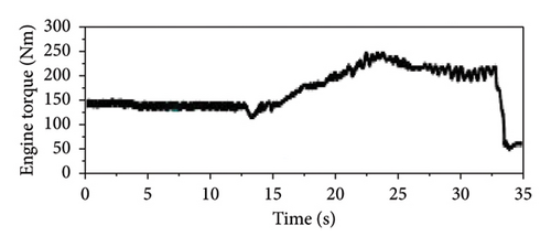
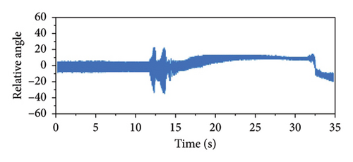
According to the vehicle testing conducted under single-cylinder misfire conditions at full load, we evaluated various parameters, including the engine speed, relative angle, primary flywheel angular acceleration, secondary flywheel angular acceleration, input shaft angular acceleration, engine torque, generator torque, drive motor torque, and accelerator pedal position and speed signals.
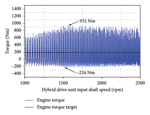
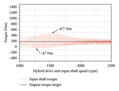
The vehicle velocity was increased from 30 to 60 km/h with the engine driving the ML pinion–wheel gear pair at full load under single-cylinder misfire. A peak torque of 187.5 Nm was targeted as the engine’s rotational speed increased from 1200 to 2400 rpm. As shown in Figure 16, the engine output torque varied between −224 and 932 Nm while the input shaft torque fluctuated from −47 to 477 Nm, indicating that the DMF damper exerted a significant vibration isolation effect.
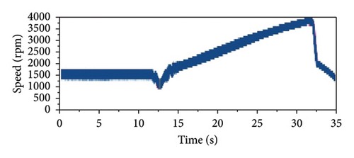
The experimental results indicated that with the ML pinion–wheel gear pair driven by the engine at full load under single-cylinder engine misfire conditions, an engine torque of approximately 150 Nm was generated when the vehicle was operating at approximately 40 km/h and the engine was running at approximately 1500 rpm. Figure 17(d) presents the experimental results calculated using the relative crankshaft angle, indicating an impact torque of approximately 380 Nm. The maximum impact torque and reverberation speed under misfire conditions were calculated according to these results, as shown in Table 7. The error between the simulated and experimental peak impact torques on the hybrid drivetrain was approximately 15%, and that between the simulated and experimental resonance speeds was approximately 5%, indicating that the simulation accurately captured the torsional behavior of the drivetrain.
| Parameter | Simulation | Experiment | Error (%) |
|---|---|---|---|
| Peak impact torque (Nm) | 436 | 380 | 86 |
| Reverberation speed (rpm) | 1050–1770 | 1000–1700 | 95 |
5.3. Engine Charging P1 Motor Under Steady-State Load
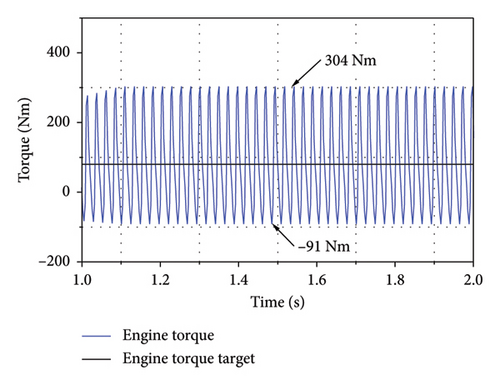
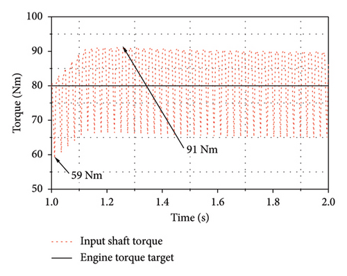
Finally, the engine was applied to generate electricity using the P1 motor at a steady-state torque of 80 Nm and a constant speed of 1300 rpm under the single-cylinder engine misfire condition. The simulation results in Figure 18 indicate that under this condition, the engine output torque varied between −91 and 304 Nm while the input shaft torque fluctuated within 59–91 Nm, indicating that the DMF damper exerted a significant vibration isolation effect.
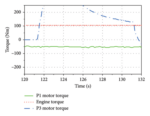
The experimental results obtained when the vehicle was propelled forward at full load by the P3 motor while the engine provided a steady-state output torque of approximately 100 Nm to the P1 motor are shown in Figure 19. The primary angular acceleration of the damper mass was 1926 rad/s2; following isolation by the damper, the angular acceleration of the input shaft was 263 rad/s2, which was below the threshold of 500 rad/s2 for effective internal control.

6. Conclusion
We established a simulation model of a hybrid drive system with multiple degrees of freedom to investigate the torsional shock characteristics of the engine under normal and engine misfire conditions. Factors such as the torsional stiffness, gear-pair meshing stiffness, and the moments of inertia for the damper, generator, and drive motor were considered.
The effects of SMF and DMF torsional dampers on the impact torque applied to the power transmission system were evaluated under normal and misfire conditions. The results indicated that when the engine drove the vehicle forward, the maximum angular accelerations experienced in the second-order vibration mode when the SMF and DMF dampers were used were both close to 540 rad/s2, indicating comparable performance. When the engine using the SMF damper with a torque ring experienced a single-cylinder misfire, the impact torque was < 500 Nm. Similarly, properly designed first- and second-stage DMF stiffnesses limited the impact torque to 500 Nm. The DMF damper was subsequently applied to the hybrid powertrain evaluated in this study.
The effects of various combinations of DMF damper stiffnesses on the impact torque experienced by the system under conditions of engine misfire were subsequently investigated. We utilized a second-stage stiffness of 10 Nm/deg while systematically varying the first-stage stiffness. The results indicated that reducing the first-stage stiffness increased the impact torque. Furthermore, when the first-stage stiffness was 5.5 Nm/deg, the impact torque increased slightly with an increase in the second-stage stiffness. Thus, a first-stage stiffness of 5.1 Nm/deg and second-stage stiffness of 15.0 Nm/deg were applied in the subsequent analyses, considering the damper manufacturer constraints.
Finally, the impact torque within the power transmission system was assessed while the vehicle operated under full engine load conditions, both in normal operation and during instances of engine misfire, as well as at a steady-state engine load to operate the P1 motor for electricity generation. The results indicated that the impact torque in the power transmission system met the design requirements, with an error of approximately 15% between the simulated and measured peak impact torques and an error of approximately 5% between the simulated and measured impact resonance speeds.
The DMF damper design methodology presented herein can be adapted for implementation within the power transmission systems of ships, to mitigate the impacts of vibration and shock on the vessel’s structural integrity and its equipment. Moreover, it is applicable to the design of transmission systems in engineering machinery, industrial equipment, and the aerospace industry.
Currently, the simulation method is limited to the analysis of steady-state conditions. In contrast, computing transient conditions involves a substantial workload and results in reduced accuracy; thus, it is essential to explore adaptive control methods. This study primarily focused on single-cylinder misfire scenarios, and there is potential for expansion into additional contexts. This emphasis arises from the fact that misfire events can occur under various circumstances, e.g., a 3% random misfire condition at full throttle, an 11% random misfire condition at full throttle, an 18% random misfire condition at full throttle, single-cylinder misfires under varying loads, and multicylinder misfires at full throttle.
Nomenclature
-
- ML
-
- Mechanical low
-
- MH
-
- Mechanical high
-
- P1 motor
-
- Motor located at the output of the engine
-
- P3 motor
-
- Motor located at the output of the transmission
-
- SMF
-
- Single-mass flywheel damper
-
- DMF
-
- Dual-mass flywheel damper
-
- CTD
-
- Clutch torsional damper
-
- CPVA
-
- Centrifugal pendulum vibration absorber
Conflicts of Interest
The authors declare no conflicts of interest.
Funding
No funding was received for this research.
Acknowledgments
We extend our gratitude to experts Wu Xiaofei from the Pan Asia Automotive Technology Center for their guidance in enhancing the accuracy of the simulation model. We would like to thank Editage for English language editing.
Open Research
Data Availability Statement
The data that support the findings of this study are available from the corresponding author upon reasonable request.


