Rubbing Dynamics of Dual-Disk Rotor System Supported by Oil Film Bearing
Abstract
As the clearance between the rotor and the casing gradually becomes smaller, the probability of collision and friction increases greatly, the rubbing dynamics of the dual disk-shaft-bearing system is studied in this paper. Considering the gyro effect of rotor, a dynamic model of the rotor system under nonlinear oil film force is established; the matrices of Timoshenko beam and coupled rigid disk elements are obtained and the rotor support is described by the analytical formula of Capone nonlinear oil film force. Taking the deformation and energy dissipation into account during the rubbing, the rubbing stiffness is characterized by using nonlinear Hertz contact theory. It is innovative to study the mechanism of the rub-impact dynamics for the rotor system considering the nonlinear oil film force of sliding bearing. The equation of motion for the rotor system is derived to investigate the effect of the rotating speed, the eccentricity, the rubbing clearance, and stiffness on the nonlinear dynamic responses. The results indicate that the rotational speed, the eccentricity, rubbing clearance, and stiffness have significant effect on the nonlinear dynamic behaviors of the dual-disk rotor with the sliding bearings; the system presents complex dynamic behaviors such as period, multiperiod, quasiperiod, jumping, and paroxysmal chaos. From the perspective of rotor stable operation, there are optimal ranges of the speed, eccentricity, and rubbing parameter, and these parameters should be considered comprehensively to avoid the rotor working in nonlinear motion states such as chaos and quasiperiod. The research work has important guiding significance for the selection of rotor balance accuracy level, design of static gap, and structure optimization.
1. Introduction
As the rotor design in modern gas turbines pursues the higher thrust to weight ratio and higher working efficiency, the static gap between the blade and the casing is getting smaller and smaller. Such factors as the mass imbalance, the fluid excitation, the looseness, and the misalignment of the rotor may cause the increase of the rotor vibration, resulting in the rubbing between the rotor and casing. Rubbing, as an instantaneous large external excitation of the rotor-bearing system, is very destructive to the high-speed rotational rotor. It will cause excessive vibrations of rotor, noise deterioration, serious rotor wear, bearing damage, and even shaft fracture. Therefore, the study of rubbing dynamics for rotor has important academic and engineering application values for the safe and stable operations of rotational machinery.
In recent years, researchers have carried out many studies on the nonlinear dynamic modeling of rotor rubbing and made much progress. Wegener et al. [1] investigates impact nonlinear vibrations of a Jeffcott rotor with an elastic retainer bearing. Liu et al. [2] established a dynamic model of a turboshaft engine with nonlinear support and rubbing faults. The variable compliance vibration and bifurcation mechanism considering the bearing clearance, the speed ratio, and the rubbing stiffness are analyzed in detail. Popprath and Ecker [3] developed a mathematical model of rotor contacting an elastically suspended stator to investigate the intermittent contact dynamics between the two components, and the research indicated that the damping of the stator has a significant effect on the movement of the rotor. Tofighi-Niaki (Reference [4]) studied the periodic, quasiperiodic, and chaotic vibrational behaviors of the rotor system with rubbing. Considering the bending and torsional vibrations of the rotor, the influences of the clearance, friction coefficient, and stator stiffness on the rubbing dynamics are investigated by Mokhtar et al. [5]. Guan Hong et al. [6] established a gear-dual-rotor dynamic model by applying the fixed interface component mode synthesis method to study the multiposition rubbing of the system. Prabith and Praveen Krishna [7] developed a dynamic model of a dual-rotor system by adopting conical Timoshenko beam element, rigid disk, and rolling contact bearing, the vibrational response of the multiple disk rubbing is calculated based on the approximate time variational method. The results show that the nonlinearity of multidisk rubbing is enhanced compared with that of single-disk rubbing, and the response characteristics and stability of the system change significantly. Yang et al. [8] built a dynamic model of a dual-rotor system to simulate the unbalanced-partial rubbing coupling fault vibration of an aeroengine. The effects of speed ratio, initial clearance, and convex curvature radius on dynamic characteristics are reported. Ecker et al. [9] studied a intermittent nonlinear contact dynamics between rigid rotor and the backup bearing. Chang-Jian and Chen [10] conducted an analysis of the nonlinear dynamics for a rotor-bearing system supported by oil-film short bearings with nonlinear suspension, and their research particularly emphasized the rubbing interaction between the rotor and stator. Keogh and Cole [11] investigated the effect of contact events on vibrational signals of the rotor in magnetic bearing systems. Hou et al. [12] studied the bifurcation characteristics of the aircraft rotor system with rubbing induced by the maneuver load. Zhang et al. [13] proposed and verified the dynamic analytical method for the friction-crack rod-fastened combined rotor (RFCR) system based on the full spectrum theory and the experiments. Li et al. [14] and Ma et al. [15] proposed an improved rubbing force model which can be used to determine the contact force. Muszynska and Jones [16] presented a multidegree of freedom model of a tuned disk considering friction forces and hysteretic damping. The study showed that the irregularities in friction and excitation patterns lead to mistuning.
Many scholars have conducted extensive research on the rubbing of rotor system under the support of nonlinear oil film. By constructing complex mathematical models and utilizing numerical simulation methods, they have deeply analyzed the dynamic behavior of rotor systems caused by nonlinear oil-film forces. Ma et al. [17] developed a reduced dynamic model of dual-rotor-bearing system with squeeze film damper by combining finite element and component mode synthesis methods to analyze the effects of key parameters such as the bearing clearance and the squeeze film damper (SFD) oil film gap on the vibration of the system. Chang-Jian and Chen [18] carried out a nonlinear dynamic analysis of a system consisting of a flexible rubbing rotor supported by an oil film bearing. Xiang et al. [19] established a mathematical model of asymmetric double-disk rotor-bearing system considering nonlinear oil film force and rubbing force. The research results show that the nonlinear dynamic behavior of the system changes with the variation of rotational speed and model parameters. Pan et al. [20] established a six-node rubbing rotor system model including novel blade-casing rubbing force, the climbing motor load, the rolling bearing nonlinear Hertz contact force, the rotor unbalanced force, the gravity field, and the squeeze oil film force. It is found that the change of oil film clearance has the greatest influence on the rubbing response of the system, and the change of rubbing stiffness has the least influence on the rubbing response of the system. Ma et al. [21] built a lumped mass model of the rotor-bearing-seal system considering the gyroscopic effect, and studied the influence of the rotational speed and eccentricity of the rotor system on the oil film stability of the rotor bearing seal system under two loading conditions. Xu et al. [22] proposed a four-degree-of-freedom (4-DOF) hydrodynamic model of SFD considering the influence of radial displacement on oil film clearance and rotational displacement. The oil film clearance distribution and static characteristics of SFD under different rotational displacements and radial eccentricity were analyzed by simulation and experiment. Xiang et al. [23] studied the parametric instability of a rotor-bearing system with crack and rubbing coupling defects under nonlinear oil film force. Sun et al. [24] proposed the mathematical model of the rotor bearing system. The bifurcation diagram, cascade spectrum, time history, phase diagram, power spectrum, and Poincare diagram were used to analyze the influence of rotational speed, oil film temperature, and rotor eccentricity on the stability of the rotor bearing system. Hu et al. [25] presented a model considering nonlinear friction impact force and nonlinear oil film force and analyzed the complex nonlinear vibration of rotor-bearing system.
The researchers have made lots of study on the rubbing dynamics of the rotor system and the dynamic characteristics of the rotor system under the nonlinear oil film force. However, there are few studies on the rubbing for the rotor system considering the nonlinear oil film force. The rubbing of this complex rotor system has a great influence on the safe and stable operation of the unit. Therefore, the rubbing dynamic model of the dual-disk rotor with sliding bearing considering the gyro effect is established, and the effect of the rotational speed, the mass imbalance, and the rubbing clearance and stiffness on the vibrational responses of the system are analyzed in this paper. This research work is novel in the dynamic modeling of the complicated rotor system under the nonlinear oil film force of sliding bearing. The research has important engineering application value and academic value for the intelligent operation and maintenance of multidisk rotor system with sliding bearing.
2. Modeling of the Shaft-Disk-Bearing System
2.1. Modeling of Shaft Based on Timoshenko Beam Theory

2.2. Modeling of Disk
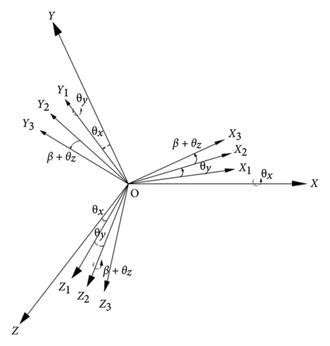
The motion of the disk can be decomposed into the translational motion and rotational motion. The translational motion is the combined motion of the horizontal and vertical directions. The rotation of rotor can be decomposed into the autorotation around the rotor’s center line and the revolution around the static center line. Letting the spin velocity be Ω, and then after time t, the rotation angle is Ωt. The fixed coordinate system OXYZ of the disk is established, as seen in Figure 2. The OXYZ is rotated around the X axis to generate OX1Y1Z1 and then OX1Y1Z1 is rotated around the Y1 axis to generate OX2Y2Z2. The final coordinate system OX3Y3Z3 is obtained by means of rotating OX2Y2Z2 by (β + θZ) around the Z2 axis.
2.3. Modeling of Sliding Bearing
When the nonlinear dynamics of the rotor is studied, the influence of the oil film force on the displacement needs to be focused on. In this study, the short bearing is adopted, the assumption is made that the oil film satisfies the Gumbel oil film boundary condition, that is, there is a complete oil film in the convergence zone of the oil film gap, and the oil film in the diffusion zone is completely broken. In order to analyze the physical cause of the nonlinear oil film force, the schematic diagram of the sliding bearing is drawn, as shown in Figure 3. The bearing forces are regarded as a nonlinear supporting force for studying on the nonlinear dynamic characteristics of the complex rotor system, the more complex mechanical behavior of sliding bearings is not taken into account in this research.
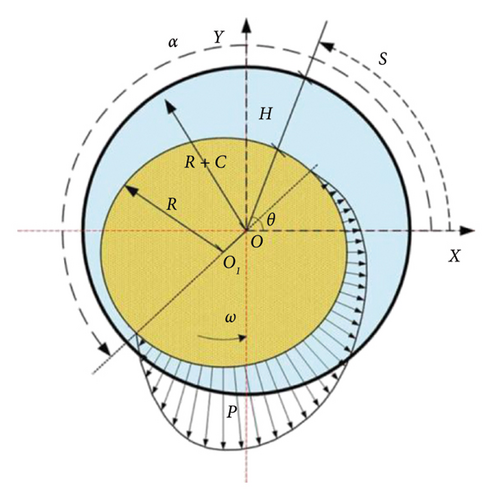
In Figure 3, O and O1 are the geometric center of the bearing inner liner and journal, respectively, ω is the rotating speed of the rotor, P is the dynamic pressure of oil film, S is the circumferential rotational angle displacement of the rotating shaft, α is the initial positive pressure angle of oil film, and R, C, and H are the journal radius, bearing clearance, and oil film thickness, respectively. If there is a thin oil film with an average thickness of H between the journal and the shaft, the thickness H becomes uneven along the bearing wall direction as the rotor rotates, resulting in nonuniform oil pressure along the journal ring direction, producing nonlinear oil film force.
From Equation (31), it can be found that the oil film force on the journal is closely related to the displacement and velocity of the journal in the radial and tangential directions and the initial positive pressure angle of the oil film; the oil film force has strong nonlinearity. The dimensionless nonlinear oil film force of the journal can be calculated by applying Equation (30) on the node where the sliding bearing is located.
2.4. Modeling of Rub-Impact Between Rotor and Stator
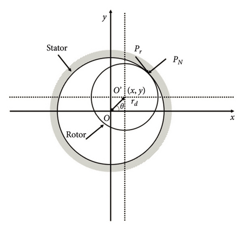
The rub impact studied in this paper refers to the collision and friction between the rotor (impeller or bladed disk) and the stator, the rub-impact may be the blades and the cylinder, the blades and the sealing teeth, the blades and the diaphragm, and the impeller and the stator; this type of rub-impact is often point–point rub-impact, it can be described by using Figure 4. In engineering, the rub-impact often occurs when the rotor system vibration is too large and the amplitude is greater than the gap between the rotor and the stator. The rub-impact poses a great threat to the safe and stable operation of the rotor system. The research on the influence of the rub-impact on the rotor dynamic characteristics has important academic value and engineering application value. In this study, it is assumed that the collision is an elastic collision, and the deformation and energy dissipation of the rubbing process are considered. The dynamic model of rubbing is shown in Figure 4, where rd is the radial displacement of the rotor and θ is the revolution phase angle of the rotor at the rubbing node. PN and PT are the normal force and the tangential friction force during the process of rubbing, respectively. If the initial gap between the rotor and the stator is δ, when the displacement of the rotor is greater than the initial gap δ, the system will have a rubbing fault, and the tangential friction will also generate torque on the rotor.
In this research, the commonly used aluminum–silicon polyphenylene resin is selected as the coating material, and the performance parameters of the material are shown in Table 1.
| Elastic modulus of coating E2 (Gpa) | Poisson ratio of coating a2 | Initial clearance δ (mm) | Coefficient of friction f | Energy consumption constant α (s/m) |
|---|---|---|---|---|
| 2.08 | 0.25 | 0.45 | 0.1 | 0.16 |
2.5. Equation of Motion for the Coupling Rotor System
M, G, C, and K in Equation (37) are the total mass matrix, the total gyroscopic matrix, the total damping matrix, and the total stiffness matrix of the rotor-bearing system, respectively. C = αM + βK, where α and β are two scale coefficients and are related to the mass matrix M and stiffness matrix K, respectively; F is the generalized force vector of the rotor-bearing system.
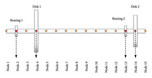
In the calculation example in this research, the number of nodes n = 15 is selected to establish the finite element model of the rotor-bearing system, as shown in Figure 5. The total length of the rotating shaft is 0.7 m, and the diameter of the shaft is 0.02 m. The materials of the disk and the shaft are the same, and the parameters of the rotor-bearing system are shown in Table 2. If the length of each beam element is 0.05 m, the corresponding matrices of 14 beam elements are assembled to obtain the total stiffness matrix, total mass matrix and gyro matrix for the shaft, and then the coupling mass matrix, stiffness matrix, damping matrix and gyro matrix for the Disk 1 and Disk 2 are assembled on the matrix of the corresponding node of the shaft. The sliding bearings are at Nodes 2 and 13, respectively, and the nonlinear oil film force derived in Section 2.3 is loaded in the generalized force vector of the corresponding node. Finally, considering the unbalanced force of the rotor and the gravity of the rotor-bearing system, the bending-torsion coupled vibrational equation of the unbalanced rotor-bearing system is established.
| Parameter names | Unit | Parameter values |
|---|---|---|
| Rotor elastic modulus E1 | Pa | 2.11 × 10¹¹ |
| Material density ρ | kg/m3 | 7850 |
| Poisson ratio μ | / | 0.3 |
| Mass of Disk 1 Ma1 | kg | 2.45 |
| Radius of Disk 1 r1 | m | 0.1 |
| Mass of Disk 2 Ma2 | kg | 1.385 |
| Radius of Disk 2 r2 | m | 0.075 |
| Unbalanced mass of Disk 1 Mb1 | g | 2 |
| Unbalanced mass of Disk 2 Mb2 | g | 1 |
| Eccentricity of Disk 1 e1 | mm | 0.5 |
| Eccentricity of Disk 2 e2 | mm | 0.5 |
| Pole moment of inertia of Disk 1 Ip1 | kg·m2 | 1.23 × 10⁻² |
| Diameter inertia of Disk 1 Id1 | kg·m2 | 6.15 × 10⁻³ |
| Pole moment of inertia of Disk 2 Ip2 | kg·m2 | 3.9 × 10⁻³ |
| Diameter inertia of Disk 2 Id2 | kg·m2 | 1.95 × 10⁻³ |
| Length of sliding bearing l | mm | 12 |
| Clearance of sliding bearing C | mm | 0.11 |
| Radius of sliding bearing R | mm | 25 |
| Oil viscosity μ | Pa·s | 0.018 |
| Diameter of shaft r | m | 0.02 |
3. Influencing Factors of Dynamic Characteristics for the Rotor System
In order to solve the nonlinear set of differential equations, the fourth order fifth order Runge–Kutta method with variable step is adopted in this research, namely, the fourth order method is used to provide candidate solutions, the fifth order method is applied to control the error, and the overall cutoff error can be controlled. The influence of parameters such as the rotational speed, the eccentricity, the rub-impact gap, and the rub-impact stiffness on the nonlinear dynamic characteristics will be studied in the following sections.
3.1. Rotating Speed
Rotational speed is a very important basic parameter in the operation of the rotor system. The variation of rotational speed will affect the unbalanced force and aerodynamic force, resulting in the change of the rotor vibration. In addition, the relative relationship between the working rotational speed and the critical rotational speed will also have a significant impact on the vibrations. Therefore, it is very essential to study the influence of the rotation speed on the safe and stable operation of the rotor system.
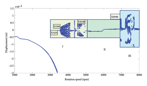
The Disk 2 is taken as research object, the influence of the rotational speed on the nonlinear dynamics of the unbalanced rotor system with the rubbing is studied in this section. With the rotational speed as the horizontal coordinate and the vibration of the Disk 2 (Node 14) as the ordinate, the range of the rotation speed is 1000 rpm–8000 rpm and the step of the rotation speed is 20 rpm, and the bifurcation diagram of the rotor vibration with the rotation speed is drawn, as shown in Figure 6. It can be seen from Figure 6 that the rotor system exhibits rich nonlinear dynamic characteristics. In the low speed range of 1000 rpm–3400 rpm, the bifurcation diagram shows a straight line, the rotor is in the state of a stable period-1 motion; there is an obvious jump phenomenon at the 1st order bending critical speed of 3420 rpm, followed by paroxysmal chaos, that is, repeated switching between the chaos and the periodic motion. There are three typical bifurcation regions after rotor crossing the critical speed: (I) 3420 rpm–5000 rpm: the rotor appears switching between the chaotic and periodic motions, and the chaotic region is more than the periodic region. (II) 5020 rpm–6920 rpm: the system is in the periodic motion state, and the possibility of rubbing between the rotor and the stator is small and the rubbing degree is light. The rotor should be operated in this span of speed as far as possible. (III) 6940 rpm–8000 rpm: the rotor system enters completely into aperiodic motion state.
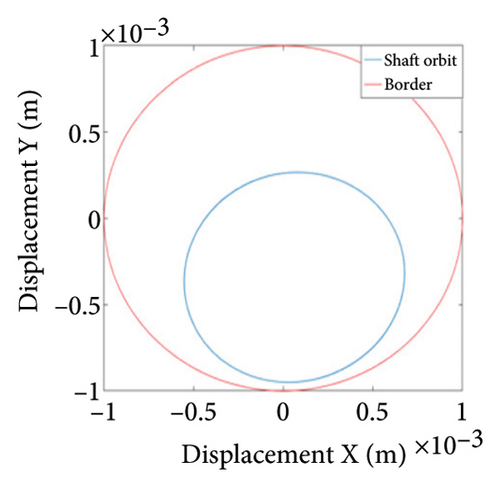
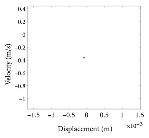
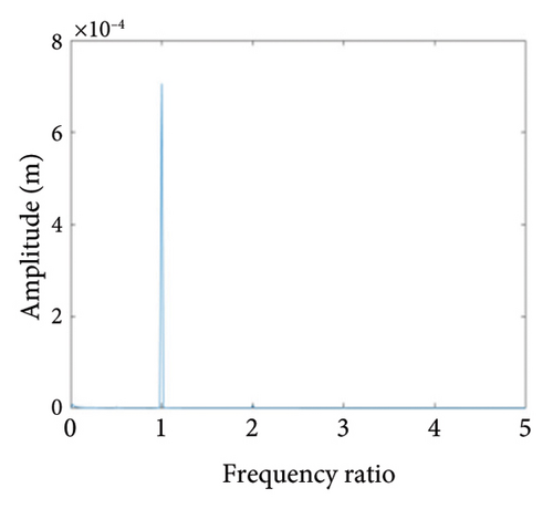
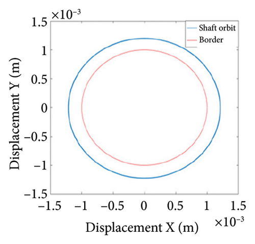
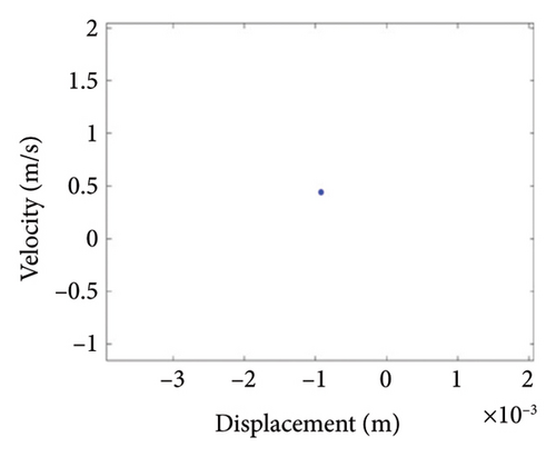
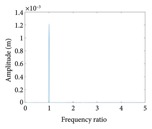
To study the typical dynamic behaviors in each region, the rotational speeds 2000 rpm, 3420 rpm, 4540 rpm, 5200 rpm, and 6000 rpm are selected to obtain corresponding shaft trajectory, Poincare, and frequency spectrum maps, as shown in Figures 7, 8, 9, 10, 11, and 12. As can be seen from Figure 7(a), when the rotating speed is 2000 rpm, the trajectory of shaft (the blue curve) does not exceed the boundary (the red curve), indicating that there is no rubbing between the rotor and the stator; there is a point in Poincare diagram, as shown in Figure 7(b); in Figure 7(c), only 1X frequency exists in the spectrum, confirming the conclusion without rubbing. As can be seen from Figure 8, when the rotation speed increases to 3420 rpm, the rotor system enters Region I, the shaft trajectory and the boundary intersect, as seen in Figure 8(a), and the rotor has slight local rubbing, but the system is still in this state of period-1 motion, as shown in Figures 8(b) and 8(c). When the rotation speed continues to increase to 4540 rpm, the trajectory becomes chaotic, as shown in Figure 9(a); Poincare diagram shows dense scattered points, as seen in Figure 9(b), indicating that the system is in a chaotic state; it can be seen from Figure 9(c) that the main frequency is 1X, and a new 0.5X frequency appears.

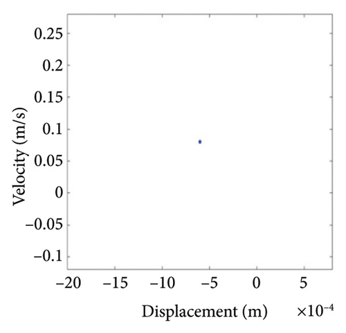
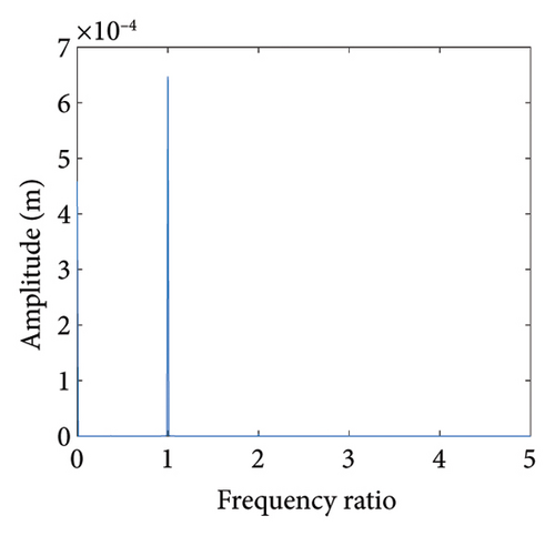
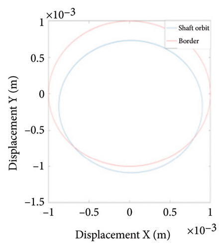
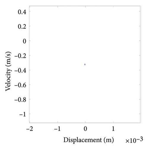
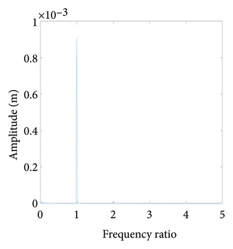
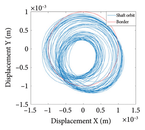
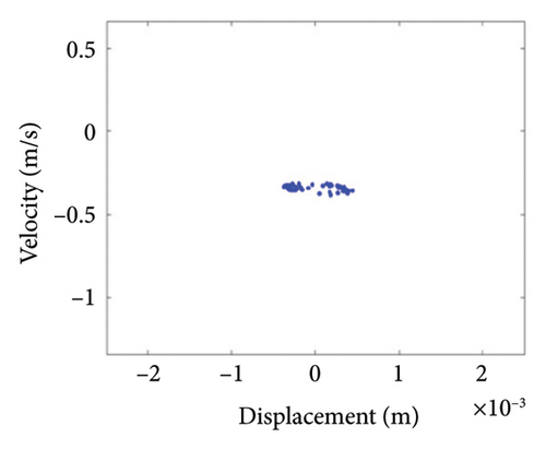
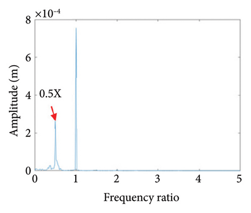
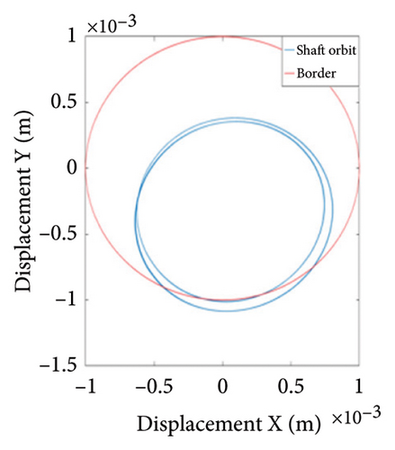
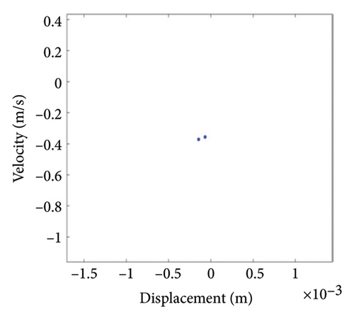
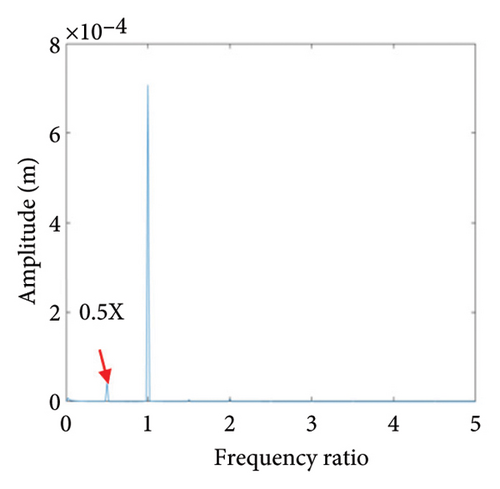
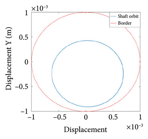
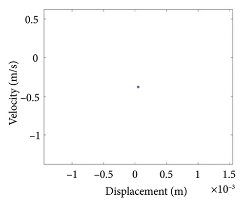

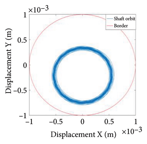
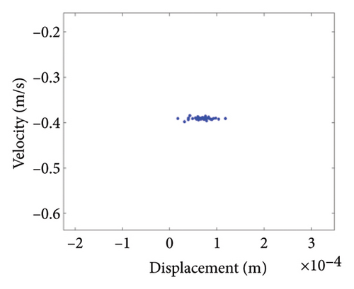
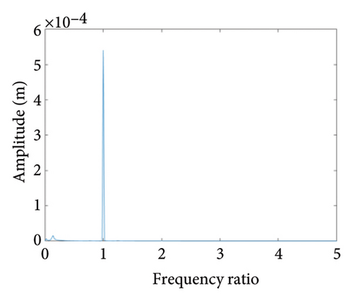
Figure 10 shows the steady-state responses of the rotor at 5200 rpm. The trajectory shows two no-overlapping ellipses, with slight local rubbing between the rotor and stator, as shown in Figure 10(a); Poincare diagram shows two single points, as shown in Figure 10(b); and the 0.5X and 1X frequencies appear in the spectrum, as seen in Figure 10(c). It is deduced from Figure 10 that the system is in state of period-2 motion. As the speed continues to increase to 6000 rpm, the shaft trajectory of the rotor is an ellipse which is not beyond the boundary. Poincare section shows isolated single points and 1X frequency on the spectrum, indicating that the system returns back to period-1 motion, as shown in Figure 11. It can be inferred that, in Region II of 5020 rpm–6920 rpm, the possibility of rubbing between the rotor and the stator is small and the degree of rubbing is slight. Therefore, the rotor should be operated in this interval as far as possible. Figure 12(a) shows a number of noncoincident elliptical tracks, indicating the system is in the state of chaotic motion, but the trajectory does not exceed the boundary, the reason for the chaos without rubbing lies in the oil film whirl; Figure 12(b) presents many random scattered points; and the 1X and some low-frequency components appear in Figure 12(c).
As can be seen from the analysis above, the rotor system shows rich nonlinear dynamic behaviors, the reasons for these phenomena are the nonlinear oil film forces and the rub-impact with strong nonlinear characteristics. The dual nonlinear factors make the dynamic characteristics of the system more complicated.
3.2. Eccentricity
Due to the error of manufacturing and installation, the rotor system has the deviation between its geometric center and centroid, which is called the eccentricity. When the rotor rotates at high speed, the presence of eccentricity will generate additional excitation force resulting in vibrations. If the vibrational amplitude is too large, it is easy to cause regenerative faults such as the rubbing and looseness of the support, the faults may lead to rotor damage. In this section, the eccentricity is selected as the bifurcation parameter and the nonlinear dynamic behaviors of Disk 2 with the different eccentricity under the rubbing fault are analyzed. The eccentricity range of 0.5 mm–1.5 mm and the working speed of 5200 rpm are chosen, and the eccentricity step is 0.005 mm, the bifurcation diagram of the displacement for Disk 2 with the eccentricity e is drawn, as shown in Figure 13.
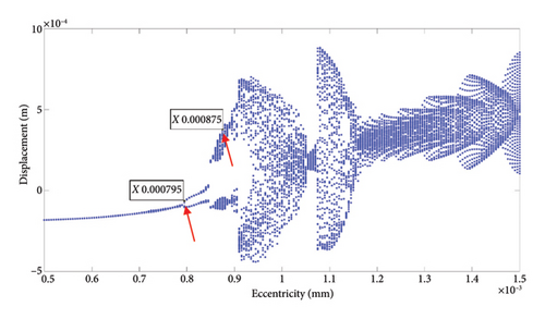
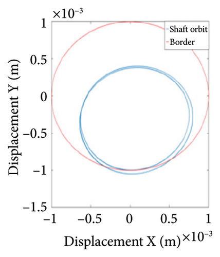
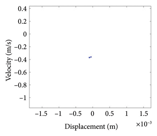
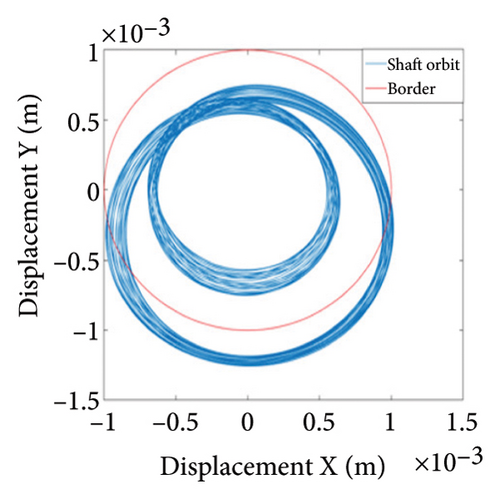
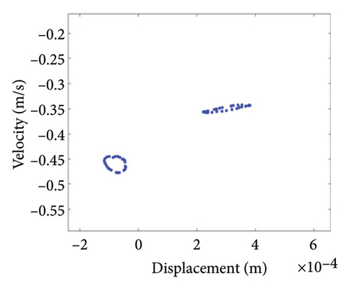
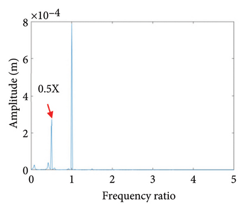
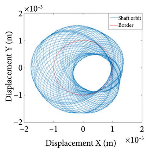
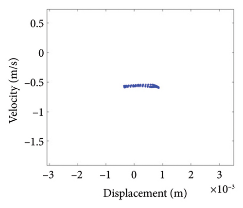
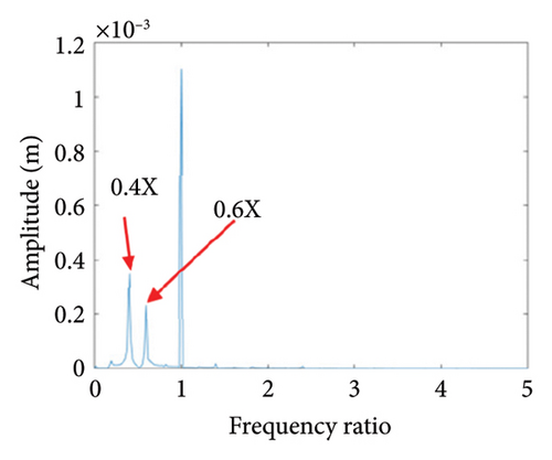
Figure 13 demonstrates abundant nonlinear dynamic characteristics. When the eccentricity is in the range from 0.5 mm to 0.79 mm, the bifurcation diagram presents a straight line, indicating that the system is in the state of period-1 motion. As the eccentricity further increases to 0.795 mm, the rotor undergoes a period-doubling bifurcation, transitioning into period-2 motion. The range of eccentricity for the period-2 motion is relatively short. Afterwards, the system enters a wide chaotic region. Steady-state response analyses are conducted for the eccentricity e = 0.7 mm, 0.8 mm, 0.875 mm, and 1.09 mm, the corresponding trajectory, Poincare and frequency spectrum are got, as shown in Figures 14, 15, 16, and 17.
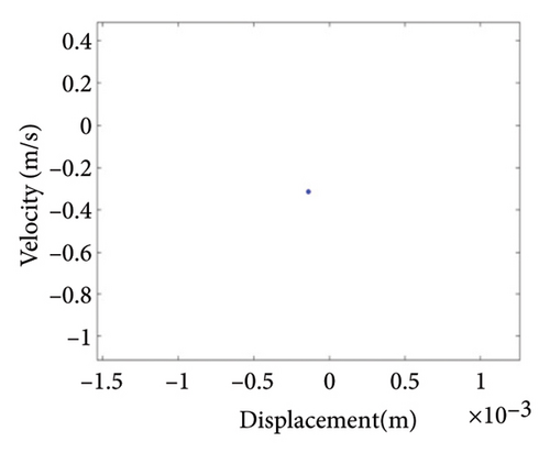
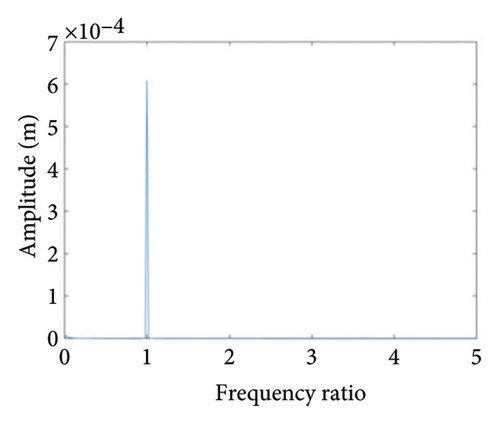
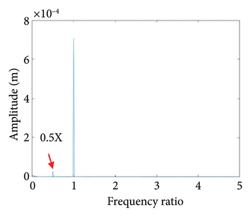
As can be seen from Figure 14(a), when the eccentricity e is 0.7 mm, the shaft trajectory does not exceed the boundary, indicating that there is no friction or impact between the rotor and stator; Poincare diagram is a single point as shown in Figure 14(b); and in Figure 14(c), only 1X frequency appears in the spectrum, indicating that the rotor is in period-1 motion and no rubbing fault occurs. It can be deduced from Figures 13 and 14 that when the eccentricity is from 0.5 mm to 0.79 mm, the unbalanced force of the rotor is small, the system is in period-1 motion state, and no rubbing fault occurs.
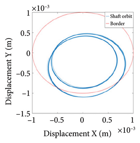
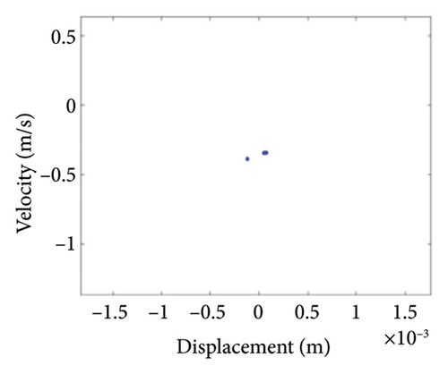
Two nonoverlapping ellipses exist in Figure 15(a), indicating a slight local rubbing between the rotor and the stator; Figure 15(b) shows two isolated points; and Figure 15(c) exhibits the 0.5X and 1X frequencies, showing that the rotor has entered the period-2 motion state and has local rubbing with the stator. As can be seen from Figure 16(a), the trajectory forms many ellipses which never coincide and are similar to two rings. Poincare diagram in Figure 16(b) evolves into two closed rings. In Figure 16(c), in addition to 0.5X frequency, 1X and other division frequencies appear, indicating that when the system enters a quasiperiodic motion, the rotor gradually begins to become unstable and has local rubbing with the stator. When the eccentricity is greater than 0.875 mm, the rotor starts to switch back and forth between the chaotic and quasiperiodic states, and the system becomes extremely unstable. As can be seen from Figure 17(a), the shaft trajectory includes infinite number of stable aperiodic orbits. Figure 17(b) shows many scatter points and Figure 17(c) exhibits 1X, 0.4X, 0.6X, and other frequencies, indicating that the rotor is in a chaotic state and has local rubbing with the stator.
In conclusion, the eccentricity has a significant influence on the nonlinear vibrations of the rotor system, and the system exhibits rich nonlinear dynamic behaviors such as periodic, multiperiodic, quasiperiodic, and chaotic motions. The study shows that a small eccentricity range of 0 mm–0.80 mm puts the system in single periodic motion; this eccentricity range is the best parameter range for the stable operation of the system; as the eccentricity increases, the rotor will enter in the state of quasiperiodic motion and chaotic motion and will collide with the stator. In general, the larger the eccentricity is, the stronger the unbalanced force of the rotor is, the greater the vibrational amplitude is, and the higher the possibility of rubbing is. However, the rubbing process itself has complex nonlinear dynamic characteristics, which cause the rotor entering the state of quasiperiod and chaos, these states are not conducive to the safe and stable operation of the rotor.
3.3. Rubbing Gap
The gap between the rotor and stator is a crucial parameter affecting the intensity of rubbing. As the modern gas turbines become more and more precise, the reserved gap between the blades and the casing is getting smaller and smaller, the smaller gap is easy to produce rubbing faults, and the larger gap will increase the gas leakage rate and reduce the efficiency; accordingly, it is necessary to design reasonable rubbing gap to achieve both stability and high performance.
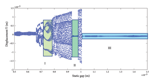
Figure 18 is the bifurcation diagram of the vibration displacement for Disk 2 in the rotor system with change of the gap at the working speed of 5200 rpm, and the step length of the gap is 0.005 mm. To facilitate the discrimination of each typical nonlinear behaviors, the bifurcation diagram is divided into the following regions: (I) 0.715 mm–0.775 mm: the rotor is in period-5 motion, subsequently entering chaos through a multiperiodic bifurcation route. The rotor is less stable in the region (II) 0.93 mm–0.98 mm: this gap region is optimal for rotor, and the system is in the state of period-1 motion without rubbing. (III) 0.98 mm–1.5 mm: the system is also in the period-1 motion without rubbing, but a larger clearance increases the gas consumption rate, resulting in reduction of work efficiency.
To study the dynamics under typical gaps, the gaps δ = 0.67 mm, 0.73 mm, 0.87 mm, 0.96 mm, 1.00 mm, and 1.20 mm are selected for analysis, the corresponding shaft trajectory, Poincare, and spectrum maps are as shown in Figures 19, 20, 21, 22, 23, and 24. It can be inferred from Figures 19, 20, and 21 that with the increase of rubbing gap, the rotor system undergoes the chaos motion with the rubbing, the period-5 motion with the rubbing and the chaotic motion with the rubbing, 0.2X, 0.4X, 0.8X, and other frequency components appear in the spectrum map, and the weight of 0.2X frequency amplitude in the total vibrations gradually increases. As can be seen from Figures 22, 23, and 24, with increasing of rubbing gap, the motion state of the system changes from chaos to period-1 motion first, then the system enters the chaos with rubbing again, and finally enters the stable period-1 motion again. It is worth noting that the amplitude of 0.2X frequency on spectrum diagram exceeds the amplitude of 1X frequency when the rubbing gap is 1 mm, indicating that the characteristic frequency of the rubbing dominates in the total vibrations.
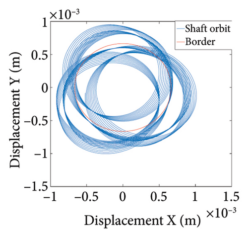
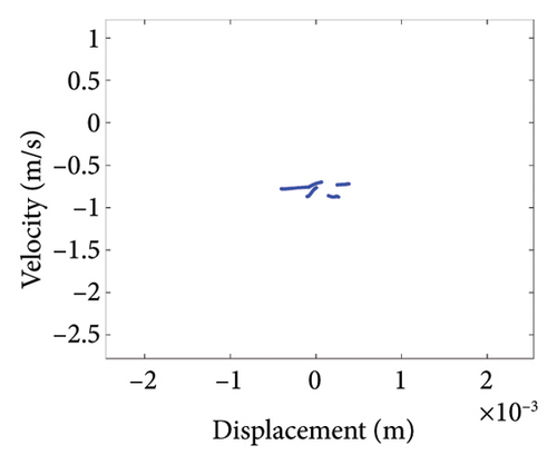
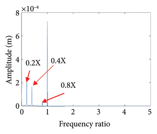
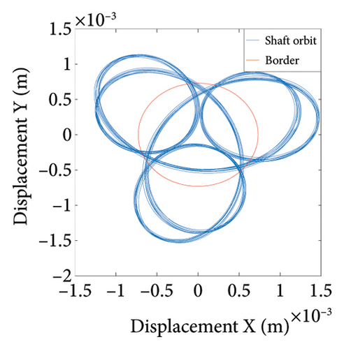
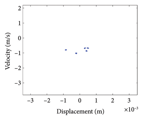
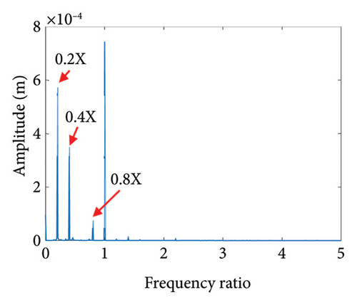
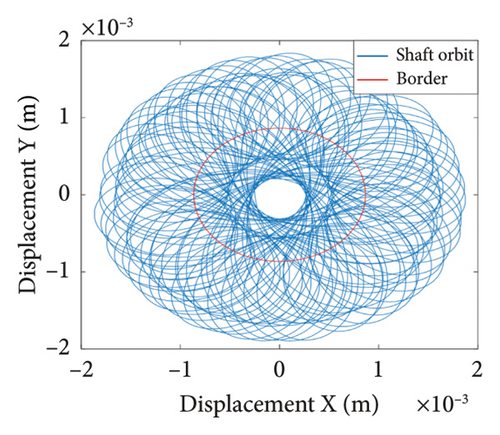
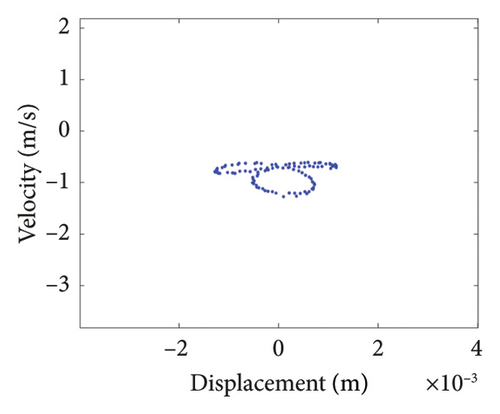
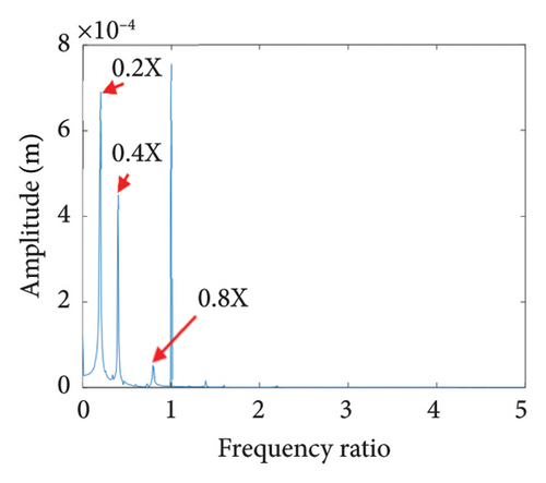
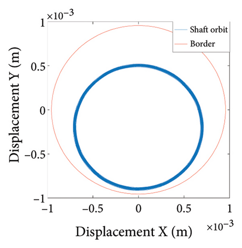
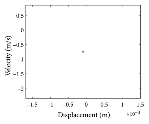
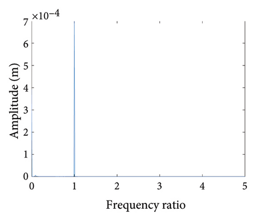
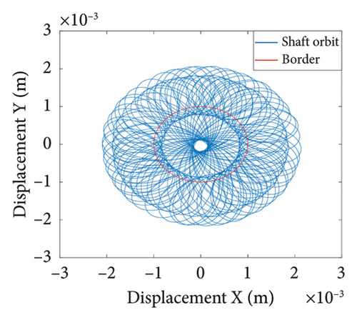
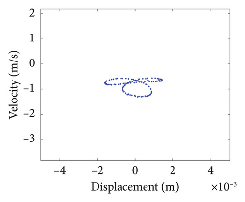
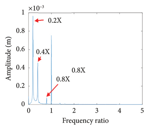
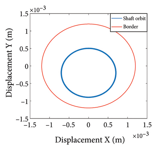
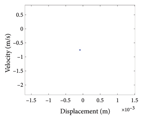
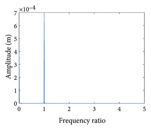
In summary, the rubbing gap is an important parameter affecting the degree of rubbing between the rotor and the stator. The rotor under different gaps has periodic motion, multiple periodic motion and chaotic motion. When the rubbing of the rotor is serious, there are chaos and multiple periodic motions which are not conducive to the safe and stable operation of the gas turbine rotor. The clearance interval of 0.93 mm–0.98 mm is the optimal interval of the rotor system, the rotor system is in period-1 motion without rubbing. The rubbing fault of the rotor occurs in the clearance range of 0.98 mm–1.005 mm, and this clearance interval should be avoided in the design. When the rubbing gap is greater than 1.005 mm, the system is in the period-1 motion and no rubbing occurs, but the larger gap will increase the gas consumption rate, resulting in a decrease of the working efficiency.
3.4. Rubbing Stiffness
The influence of the rubbing stiffness on the nonlinear dynamic behaviors of the rotor is analyzed in this section. The bifurcation diagram of the vibration displacement for Disk 2 with change of rubbing stiffness is shown in Figure 25; the relevant parameters are as follows: the working speed is 5200 rpm, the range of rubbing stiffness is 1 × 10⁶ N/m∼2 × 108 N/m, and the step length of rubbing stiffness is 1 × 10⁶ N/m.
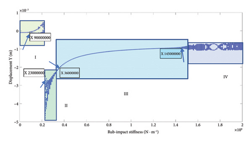
To facilitate the analysis of nonlinear behaviors for the system, the curves in Figure 25 are divided as 4 regions: (I) 1 × 10⁶ N/m∼2.2 × 107 N/m: the rotor is in a periodic motion state, and double periodic bifurcation occurs at 9 × 10⁶ N/m; (II) 2.3 × 10⁷ N/m∼3.5 × 107 N/m: the Hopf bifurcation occurs at the 2.3 × 10⁷ N/m, and the system enters into chaos through period-2 route. This stiffness range should be avoided during the design. (III) 3.6 × 10⁷ N/m∼1.45 × 108 N/m: the system is in period-1 motion and is more stable. (IV) 1.46 × 10⁸ N/m∼2 × 108 N/m: the rotor is in a complicated motion state such as the quasiperiodic and chaotic. The rubbing occurs between the rotor and stator, and the motion is complex and unstable.
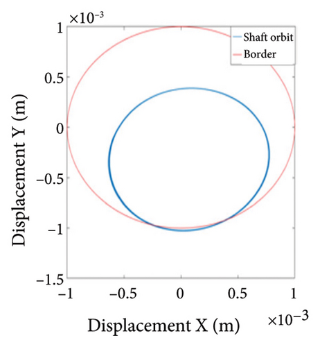
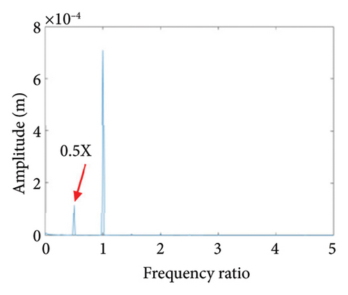
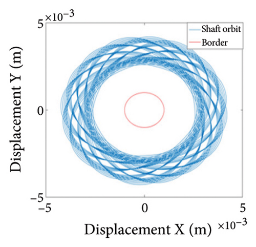
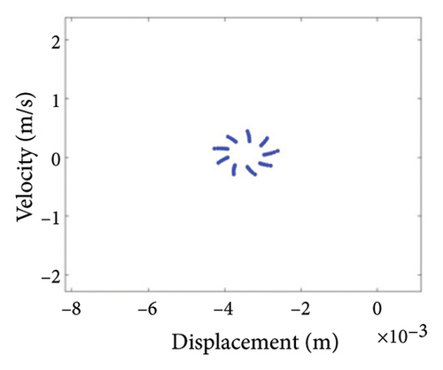
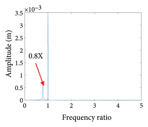
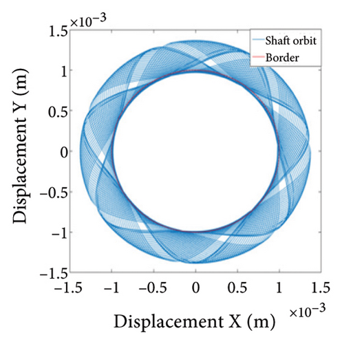
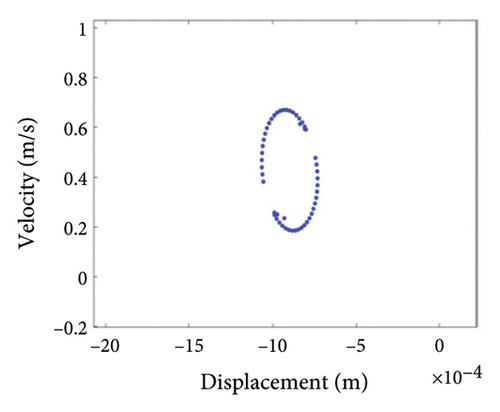
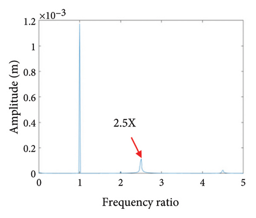
In order to more accurately analyze the nonlinear characteristics of the rotor, the rubbing stiffness 8 × 10⁶ N/m and 1.5 × 10⁷ N/m in Region (I), 2.3 × 10⁷ N/m in Region (II), 1.4 × 10⁸ N/m in Region (III), and 1.6 × 10⁸ N/m in Region (IV) are chosen to draw the shaft trajectory, Poincare, and spectrum diagrams; these figures are shown in Figures 26, 27, 28, 29, and 30. It can be seen from Figure 26 that the system is in state of period-1 motion with slight rubbing when rubbing stiffness is kr = 8 × 10⁶ N/m; with the increase of the stiffness to 1.5 × 10⁷ N/m, the system enters period-2 motion from period-1 motion with local rubbing, as shown in Figures 27(a) and 27(b); the 0.5X characteristic frequency of rubbing appears in the spectrum, as shown in Figure 27(c); Figure 28(a) shows a loop trajectory consisting of many stable aperiodic orbits; a number of scatter points are in Figure 28(b); and a novel 0.8X frequency appears in Figure 28(c). It can be inferred from Figure 28 that the rotor system gets into a chaotic state from period-2 through the Hopf bifurcation; with the increasing of the stiffness to 1.4 × 10⁸ N/m, the system enters into the state of period-1 with whole-cycle rubbing again, as shown in Figure 29; with the increasing of the stiffness to 1.6 × 10⁸ N/m, the shaft trajectory seems like intensive petal shape, it is beyond the boundary, the whole cycle rubbing occurs, as seen in Figure 30(a); Poincare diagram shows an oval shape formed by many separate points, as shown in Figure 30(b); and a fresh 2.5X frequency appears in spectrum diagram, as shown in Figure 30(c), it is deduced that the system is in quasiperiodic motion state. In practical engineering, the rotor should be in periodic motion instead of chaos or quasiperiodic motion for stable operation of the rotor.
4. Conclusions
- 1.
The rotational speed has a significant effect on the nonlinear dynamic behaviors of the dual-disk rotor system under the sliding bearing support. When the speed changes in a large range, the system presents complex dynamic behaviors such as periodic, multiperiodic, quasiperiodic, jumping, and paroxysmal chaos. In engineering practice, as the rotor is in the state of period-1 motion with stable operation and no rubbing, it is suggested that the rotor works in this speed range of 5020rpm–6920 rpm.
- 2.
The eccentricity has a notable effect on the nonlinear vibrations of the rotor system, and the system exhibits rich nonlinear dynamic behaviors such as quasiperiodic and chaotic motions. The study shows that a small eccentricity range of 0 mm–0.80 mm puts the system in period-1 motion, and this eccentricity range is the best parameter range for the stable operation of the system; as the eccentricity increases, the rotor will get into the state of multiple periodic motion, quasiperiodic motion, and chaotic motion and will collide with the stator. In general, the larger the eccentricity is, the higher the possibility of rubbing is.
- 3.
The rubbing gap is a crucial parameter affecting the degree of rubbing between the rotor and the stator. When the rubbing of the rotor is serious, there is chaos and multiple periodic motions which are not conducive to the safe and stable operation of the gas turbine rotor. The clearance interval of 0.93 mm–0.98 mm is the optimal interval of the rotor system because the rotor system is in period-1 motion without rubbing. The rubbing fault of the rotor occurs in the clearance range of 0.98 mm–1.005 mm, and this clearance interval should be avoided in the design. When the rubbing gap is greater than 1.005 mm, the system is in the period-1 motion and no rubbing occurs, but the larger gap will increase the gas consumption rate, resulting in a decrease of the working efficiency.
- 4.
The rubbing stiffness has a substantial impact on the dynamic behavior of the rotor system. Under different range of the rubbing stiffness, the system shows characteristic behaviors. (I) 1 × 10⁶ N/m∼2.2 × 107 N/m: the rotor is in a periodic motion state, and double periodic bifurcation occurs at 9 × 10⁶ N/m; (II) 2.3 × 10⁷ N/m∼3.5 × 107 N/m: the Hopf bifurcation occurs at the 2.3 × 10⁷ N/m, the system enters into chaos through period-2 route. This stiffness range brings the system into chaotic motion which is unpredictable, resulting in the irregular wear, the fatigue failure of the rotor system. Therefore, the research results are helpful for the design of rubbing stiffness. (III) 3.6 × 10⁷ N/m∼1.45 × 108 N/m: the system is in period-1 motion and is more stable. (IV) 1.46 × 10⁸ N/m∼2 × 108 N/m: the rotor is in a complicated motion state such as the quasiperiodic and chaotic, the rubbing occurs between the rotor and stator, and the motion is complex and unstable.
Conflicts of Interest
The authors declare no conflicts of interest.
Funding
This work was supported by the National Natural Science Foundation of China (Grant no. 52275118).
Open Research
Data Availability Statement
The data used to support the findings of this study are available from the corresponding author upon reasonable request.


