Dynamic Analysis of a Bolted Joint Dual-Rotor System With an Unbalanced Offset Disk Included in the Low-Pressure Rotor
Abstract
The dual-rotor structure was usually adopted in aeroengine for the sake of higher efficiency, where the high-pressure (HP) rotor and the low-pressure (LP) rotor are coupled together through an intershaft bearing. For the convenience of manufacturing and maintenance, the bolt connections are widely adopted in high-power rotors to fasten together multiple parts that are manufactured separately. The mechanical properties of the bolt connections significantly affect the rotor dynamics, which need to be precisely controlled in the design. Vibration transmission through intershaft bearings leads to complex dynamic behaviors of the bolt connection dual-rotor system, which are more difficult to control the mechanical behavior of the bolt connection. This study established the motion equations of a dual-rotor system with bolt connection structure in the HP rotor using the finite element method to deal with the effect mechanism of vibration transmission from the LP rotor on nonlinear dynamic responses of the HP rotor and the mechanical properties of the bolt connection. The Newmark method was adopted to solve the motion equations, the complicated vibration responses of the HP rotor and the mechanical properties of the bolt connection influenced by different offset positions and unbalanced force of the disk in the LP rotor are analyzed by the cascade spectrums, frequency–amplitude diagrams, time-domain waveforms, shaft obits, and bending stiffness diagram of the bolt connection. The results show that the unbalanced offset disk in the LP rotor significantly affects the HP rotor’s dynamic response and the bending stiffness of the bolt connection. Finally, the numerical simulation results are verified based on a bolt connection dual-rotor system test rig. The investigation is helpful for the dynamic modeling and simulation of the bolt connection dual-rotor system, which can be used to predict the dynamic characteristics during the design process.
1. Introduction
The bolt connection dual-rotor system is widely adopted in large-scale aeroengines for the requirement of high power and convenience of manufacturing and maintenance [1–4]. The intershaft bearing is usually adopted to combine with the dual-rotor form structure to minimize shaft deflections [5, 6]. Conversely, the vibrations of high-pressure (HP) and low-pressure (LP) rotors are transmitted to each other by means of the intershaft bearing, the dual-rotor system then exhibits highly complex dynamic properties as a result. Moreover, unlike a continuous rotor, the local stiffness of the bolted connections plays a significant role in influencing the rotor dynamics, which should be precisely controlled in the design [7–10]. Thus, investigating vibration transmission in the dual-rotor system and its impact on rotor dynamics and the bolted connection mechanical properties is crucial for the design and safety of large-scale aeroengines.
With the increasing demand for power and the thrust-weight ratio of aeroengine, the dynamic characteristics of dual-rotor systems have gradually become an important focus in recent years. For example, Prabith et al. [11, 12] built a dynamic model representing a dual-rotor system. Subsequently, the dynamic behaviors of these systems experiencing single-disk and multidisk rubimpact faults were assessed. Gao et al. [13] modeled the mathematics of an intershaft bearing with an outer raceway defect and then delved into the paroxysmal impulse phenomena in a dual-rotor system with a defective intershaft bearing via numerical approaches. The formula of defect frequency is also given in the work and verified by a dual-rotor experimental test rig. Kim et al. [14] designed a new dual-rotor wind turbine using a planetary system to improve the original problems of the complexity of design, low efficiencies, and high costs. Gao et al. [15] set up a dual-rotor model with a local defect in the inter-shaft bearing to explore the impact of the defect and the bearing’s physical parameters on rotor dynamics. Jin et al. [16] established the dynamic model of a dual-rotor system by using the finite element (FE) method to investigate the dynamic behaviors of the HP and the LP rotors with coupling misalignment and blade-casing rubbing fault. Lu et al. [17, 18] investigated the effects of the speed ratio and the space between the components of the inter-shaft bearing on the main vibrations and frequency behaviors of a dual-rotor system. They also conducted calculations to evaluate how bearing stiffness varies over time. Benbouhenni et al. [19] used a synergetic sliding mode controller to conduct the power point tracking of a dual-rotor wind power system. Rajeevalochanam et al. [20] presented a new contrarotating turbine by redesigning the LP turbine to better handle the radial distributions of inlet temperature, pressure, and swirl, which enhances the power output of the turbofan engine. Yu et al. [21–23] employed the FE method to create the governing equations of a dual-rotor system and subsequently evaluated the influence of rubimpact faults on the HP turbine disk and intershaft rubimpact on rotor dynamics. Yang et al. [24, 25] formulated the dynamic model of a dual-rotor system to analyze how fixed-point rubbing faults and blade-casing rubbing faults affect the vibration response characteristics of the rotor system.
Previous research has extensively explored the modeling and vibrations of dual-rotor systems. However, the bolt connection structure commonly found in the HP rotor of aeroengine rotor systems has not been adequately considered in existing studies. Recently, the effect of bolt connections on rotor dynamics has become a focal point, with many studies focusing on modeling methods and dynamic analysis. Hong et al. [26] proposed a new breathing model to describe asymmetrically preloads. By using the harmonic balance method, the combination resonance characteristics of a Jeffcott rotor with bolt connection were studied. By using Timoshenko beam theory and the FE method, the governing equations of the rod fastening rotor system were established by Wang et al. [27, 28]. The study then delved into the effects of internal damping and external load forms on the nonlinear dynamic properties of the rotor system. Wu et al. [29] used the contact model proposed by Greenwood and Williamson, the lateral, shear, bending, and torsional stiffness of the bolt connection in the rotor system were derived. The effects of these parameters on rotor dynamics were then numerically investigated. Yang et al. [30] established the FE model of the bolt connection of a rotor system with shaft-disk-drum structure by beam-shell-spring hybrid elements, and the influence of the number of bolts, rotating speed, and connecting stiffness on the natural characteristics are investigated. Yang et al. [31] developed a contact force model for the mating interface of a bolted connection using fractal theory. This contact model was subsequently integrated into the FE analysis of a rotor, leading to the establishment of a dynamic model for a rod-fastening rotor-bearing system. The study further investigated the impact of fixed-point rubbing faults on the stability of the rotor system’s motion. Based on experimental findings, Zhao et al. [32] proposed an improved contact model for the bolted connection interface and analyzed the influence of contact effects on the dynamic response of a gas turbine rotor system.
Currently, although extensive research has been conducted on the dynamic modeling methods for dual-rotor systems and bolted connection rotor systems and in-depth parametric studies have been carried out on the effects of bearing parameters on dual rotor and the influence of bolted connections on single-rotor systems, models of dual-rotor systems that consider the bolted connection structure are still rarely reported. In our previous works [33, 34], the bolt connection structure was modeled using a proposed bolt connection element that takes into account both the lateral and bending stiffness. Combined with the modeling method, research was conducted on the effects of connection stiffness and rubbing faults on rotor dynamics.
In the study, the equations are used to describe a dual-rotor system with bolt connections and explore how these joints work. The bolt connection structure is modeled using the proposed bolt connection element [7, 35], while the shaft is represented by the Timoshenko beam element [36–40]. The main innovative contributions of this work are summarized as follows: (1) a dynamic model of a dual-rotor system with a bolted connection structure is developed, incorporating the time-varying bending stiffness of the bolt connection and intershaft bearings. (2) The impact of the uneven position of the unbalanced disk in the LP rotor and its resulting uneven force on the movement of the HP rotor and the strength of the bolt connection is evaluated. (3) A dual-rotor test rig with a bolted connection is designed and fabricated, and dynamic tests are conducted to verify simulation results.
2. Mathematical Model for the Bolt Connection Dual-Rotor System
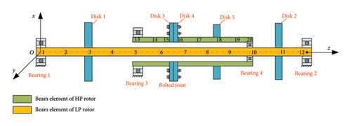
The simplified model of a dual-rotor system that includes the HP rotor is presented in Figure 1. In this system, the LP rotor and the HP rotor are held up by bearings. The HP and LP rotors are connected to each other through an intershaft bearing. All the disks are assumed to be rigid, and the shafts are flexible, which are modeled by using the Timoshenko beam element. Besides, the torsional vibration of the shaft is neglected because this work mainly looks at the bolt connection bending effect. According to the FE modeling theory, the discretization of the shaft and the location of the rigid disks and bearings can be seen in Figure 1, where the number on the shaft is the node number. Although a simplified model is established in this section, it can show how the HP rotor vibrates because of the uneven mass on disk 1 of the LP rotor, along with how the bolt connection model is built.
2.1. Bearing Force
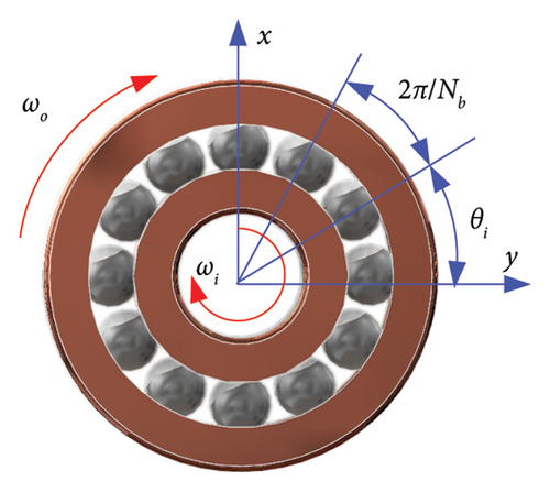
The outer races of bearings 1, 2, and 3 are assumed to be fixed to the rigid support, whereas the inner races are affixed to the rotating shaft. Therefore, the angular velocity of the outer races ωo in equation (3) should be defined as 0 when calculating the bearing forces. Moreover, the angular velocity of the inner races ωi are equal to the rotating speed of the shaft. As for the inner-shaft bearing (Bearing 4 in Figure 3), the outer and inner races are fixed to the HP and LP rotors. Consequently, the rotational speeds of the outer and inner parts of bearing 4 correspond to the HP rotor and LP rotor speeds, respectively.
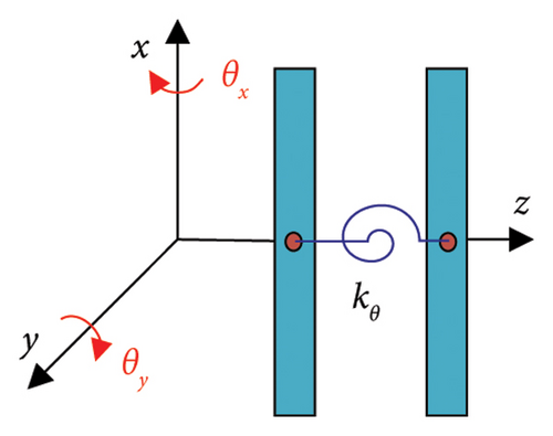
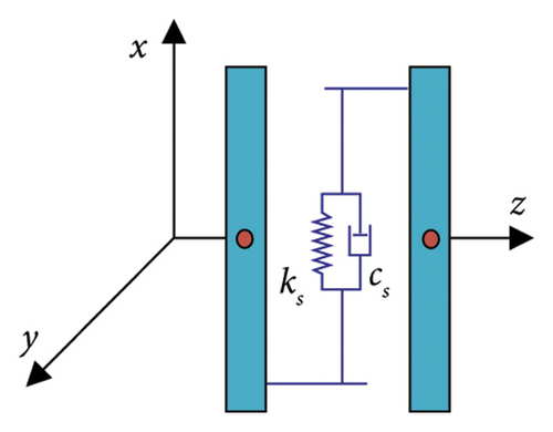
2.2. Mathematical Model of the Bolt Connection Structure
2.3. Model of the Bolt Connection Dual Rotor
It should be noted that the governing equations of the HP and LP rotors are coupled together through the inter-shaft bearing, which is illustrated by Figure 4. In Figure 4, the light blue boxes represent the beam element, which have 8 degree-of-freedoms. The yellow box represents the assembling position of the bolt connection element, and the red boxes are the rigid disks except that in the bolt connection structure. Moreover, the intershaft bearings, represented by the blue boxes, are located between the LP rotor and the HP rotor to couple the HP and LP rotors together.
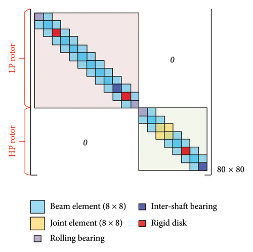
It still should be stressed that the Newmark method was used to solve the motion equations of the rotor system in the present paper due to the nonsmooth of the bending stiffness of the bolt connection. In the numerical integration, the bending stiffness in the overall governing equations need to be updated and reconstructed in each integration step.
3. Model Validation
In the literature [24], the dual-rotor system responses at different rotational speeds are obtained by simulation. Moreover, the experimental results of a dual-rotor test rig were given to verify the results. For the purpose of verify the established bolt connection dual-rotor model, in this section, the simulation results of the present work should be compared with that given in the Yang’s work [24] under the similar simulation conditions by replacing the turbine disk of HP rotor with bolt connection. In addition, the physical parameters of the rotor system should be kept as consistent as possible. The physical parameters of the bolt connection dual-rotor system with the bearings are detailed in Tables 1 and 2.
| Physical parameter | Value |
|---|---|
| LP shaft length lL (m) | 0.706 |
| LP shaft outer radius of RL (m) | 0.0125 |
| LP shaft inner radius of rL (m) | 0.0075 |
| HP shaft length lR (m) | 0.5011 |
| HP shaft outer radius RH (m) | 0.02 |
| HP shaft inner radius rH (m) | 0.015 |
| Diametral moment of inertia Jd1 (kg·m2) | 0.0805 |
| Diametral moment of inertia Jd2 (kg·m2) | 0.0884 |
| Diametral moment of inertia Jd3 (kg·m2) | 0.0409 |
| Diametral moment of inertia Jd4 (kg·m2) | 0.0409 |
| Diametral moment of inertia Jd5 (kg·m2) | 0.0882 |
| Polar moment of inertia Jp1 (kg·m2) | 0.161 |
| Polar moment of inertia Jp2 (kg·m2) | 0.1769 |
| Polar moment of inertia Jp3 (kg·m2) | 0.0818 |
| Polar moment of inertia Jp4 (kg·m2) | 0.0818 |
| LP shaft length lL (m) | 0.1765 |
| Shaft elastic modulus E (GPa) | 210 |
| Shaft Poisson’s ratio ν | 0.3 |
| Density of the rotor ρ (kg/m3) | 7928.56 |
| Lateral stiffness of bolt connection ks (N/m) | 1.97 × 10¹⁰ |
| Bending stiffness at Stage 1 kθ1 (Nm) | 1 × 10⁸ |
| Bending stiffness at Stage 2 kθ2 (Nm) | 1 × 10⁸ |
| Mass of disk m1 (kg) | 10.2 |
| Mass of disk m2 (kg) | 10.86 |
| Mass of disk m3 (kg) | 5.175 |
| Mass of disk m4 (kg) | 5.175 |
| Mass of disk m5 (kg) | 10.7 |
| Eccentricity of disk e1 (m) | 0 |
| Eccentricity of disk e2 (m) | 2 × 10⁻⁵ |
| Eccentricity of disk e3 (m) | 0 |
| Eccentricity of disk e4 (m) | 0 |
| Shaft elastic modulus E (GPa) | 2 × 10⁻⁵ |
| Number of the bearing | Bearing outer race radii R (mm) | Bearing inner race radii r (mm) | Number of balls in the bearing Nb | Contact stiffness (N/m3/2) | Bearing radial clearance γ0 (μm) | Mass (kg) |
|---|---|---|---|---|---|---|
| Bearing 1 | 10.5 | 7.5 | 9 | 1.5 × 10⁶ | 1 | 1 |
| Bearing 2 | 10.5 | 7.5 | 9 | 1.5 × 10⁶ | 1 | 1 |
| Bearing 3 | 20 | 24.8 | 8 | 3 × 10⁶ | 1 | 2 |
| Bearing 4 | 12 | 7.5 | 9 | 1.5 × 10⁶ | 1 | 1.5 |
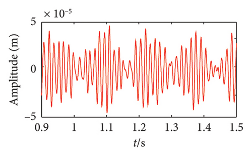
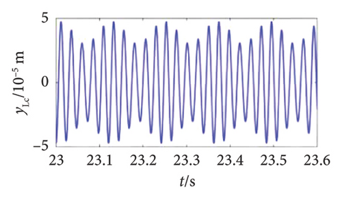
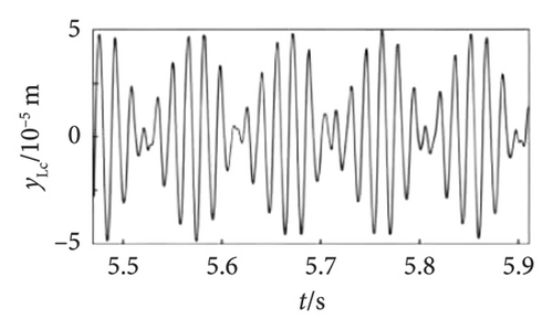
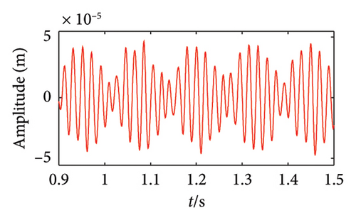
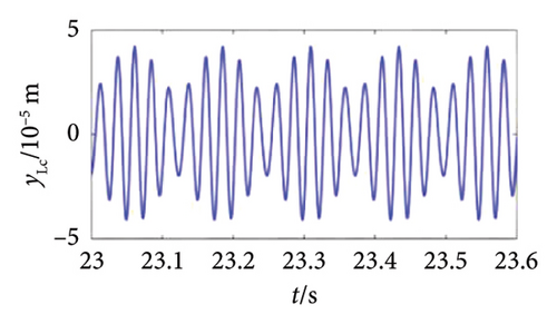
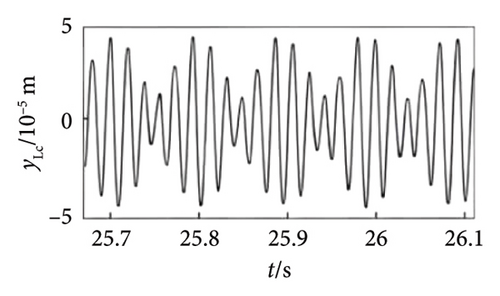
Figures 5 and 6 are, respectively, the comparisons of vibration displacements of Disk 1 at ωL = 278.1 rad/s, ωH = 328.3 rad/s, and ωL = 252.6 rad/s and ωH = 301.2 rad/s of this work in comparison with the numerical and experimental results reported by Yang [24]. It can be seen from the figures that the results are similar with that shown in the literature [24]. Therefore, the model described in this work is proven to be correct. Moreover, the variable ς = ωL / ωH is defined to investigate the impact of speed ratio on the dynamics discussed in the literature. The results of Reference [20] show that the system responses will exhibit as the beat vibration when ς is close to 1. Apparently, the result of this work accords with this conclusion; therefore, the model is correct. It should be mentioned that in the model of Yang [24], the support is simulated by the linear stiffness-damping model. However, the bearing forces model are used in the present work so that the vibration waveforms of this work shown in Figures 5 and 6 differed slightly from the results given in the comparison literature. Moreover, although the present work fails to provide a comparison in the corresponding frequency signals because such signals are not displayed in Yang’s work [24], the consistency in the time-domain signal is also enough to indicate the validity of our model.
4. Results and Discussion
In this section, the influence of Disk 1 (as depicted in Figure 1) on the dynamic behavior of the HP rotor and the mechanical characteristics of the bolt connection was assessed using numerical simulation techniques. The Newmark method was employed to integrate the equations of motion for the rotor system, with a time step size set at 6.25 × 10⁻⁵ s. The impact of Disk 1 offset position and eccentricity on the rotor system was analyzed through amplitude–frequency curves, frequency spectra, time-domain signals, shaft orbits, and the bending stiffness of the bolt connection. The simulation utilized the parameters of the dual-rotor system with bolt connections and the bearings, which are detailed in Tables 3 and 4.
| Physical parameter | Value |
|---|---|
| LP shaft length lL (m) | 2 |
| LP shaft outer radius of RL (m) | 0.0401 |
| LP shaft inner radius of rL (m) | 0 |
| HP shaft length lR (m) | 0.5011 |
| HP shaft outer radius RH (m) | 0.0075 |
| HP shaft inner radius rH (m) | 0.0042 |
| Diametral moment of inertia Jd1 (kg·m2) | 0.0042 |
| Diametral moment of inertia Jd2 (kg·m2) | 0.0021 |
| Diametral moment of inertia Jd3 (kg·m2) | 0.0021 |
| Diametral moment of inertia Jd4 (kg·m2) | 0.0042 |
| Diametral moment of inertia Jd5 (kg·m2) | 0.0084 |
| Polar moment of inertia Jp1 (kg·m2) | 0.0084 |
| Polar moment of inertia Jp2 (kg·m2) | 0.0042 |
| Polar moment of inertia Jp3 (kg·m2) | 0.0042 |
| Polar moment of inertia Jp4 (kg·m2) | 0.0084 |
| Shaft elastic modulus E (GPa) | 210 |
| Shaft Poisson’s ratio ν | 0.3 |
| Density of the rotor ρ (kg/m3) | 7800 |
| Lateral stiffness of bolt connection ks (N/m) | 2.5 × 10¹⁰ |
| Bending stiffness at Stage 1 kθ1 (Nm) | 0.006 |
| Bending stiffness at Stage 2 kθ2 (Nm) | 8.73 × 10⁶ |
| Mass of disk m1 (kg) | 8.73 × 10⁵ |
| Mass of disk m2 (kg) | 8 |
| Mass of disk m3 (kg) | 4 |
| Mass of disk m4 (kg) | 4 |
| Mass of disk m5 (kg) | 8 |
| Eccentricity of disk e1 (m) | 3 × 10⁻⁵ |
| Eccentricity of disk e2 (m) | 3 × 10⁻⁵ |
| Eccentricity of disk e3 (m) | 3 × 10⁻⁵ |
| Eccentricity of disk e4 (m) | 3 × 10⁻⁵ |
| Number of the bearing | Bearing outer race radii R (mm) | Bearing inner race radii r (mm) | Number of balls in the bearing Nb | Contact stiffness (N/m3/2) | Bearing radial clearance γ0 (μm) | Mass (kg) |
|---|---|---|---|---|---|---|
| Bearing 1 | 63.9 | 10.4 | 8 | 13.34 × 10⁹ | 1 | 2 |
| Bearing 2 | 63.9 | 10.4 | 8 | 13.34 × 10⁹ | 1 | 2 |
| Bearing 3 | 75.1 | 135.2 | 7 | 5 × 10⁸ | 1 | 4 |
| Bearing 4 | 60.1 | 75.1 | 9 | 10.5 × 10⁸ | 1 | 2.5 |
4.1. Effect of the Offset Unbalanced Disk
In this section, Disk 1 depicted in Figure 1 is designated as the unbalanced disk. Subsequently, the influence of the offset position of the unbalanced disk on HP rotor responses and the mechanical properties of the bolt connection is numerically investigated. In the numerical integration, the bolted connection bending stiffness is computed using equations (15) and (16) and is documented for comparison to elucidate the impact of Disk 1’s offset position. The dynamic characteristics are characterized through amplitude–frequency curves, spectrum cascades, time histories, shaft orbits, and stiffness diagrams.
To describe the offset position of the unbalanced disk, three numerical simulation cases are selected, namely, Disk 1 located at node nos. 3, 4, and 5 (see Figure 1), respectively, defined as P1, P2, and P3. The rotational speed ratio ς = ωL / ωH is defined as 1.2 and then the amplitudes of the bolt connection in x-direction within ωH = [900∼6000] rev/min under the three selected numerical cases is obtained and shown in Figure 7. In Figure 7(a), two prominent peaks are evident at speeds below 2200 rev/min. These peaks correspond to the 1st- and 2nd-order resonances, which are observed at approximately ωH = 1530 rev/min and 1830 rev/min. Further investigation reveals that the position of the unbalanced disk has a substantial effect on both the critical speeds and the vibration amplitudes of the HP rotor. To better understand how the position of the unbalanced disk affects the critical speeds of the HP rotor, a detailed examination of the amplitude–frequency curve within the range of ωH = 1200–2100 rev/min is provided in Figure 7(b). This local analysis shows that as the unbalanced disk shifts closer to the HP rotor, the first and 2nd-order critical speeds both decrease. Simultaneously, the amplitude associated with the 1st-order critical speed increases, while the amplitude at the 2nd-order critical speed diminishes. This is primarily due to the changes in the unbalance force and mass distribution caused by the eccentric disk position changes within the LP rotor system, which in turn influences the rotor system’s critical speeds and vibration amplitudes.
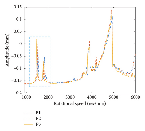
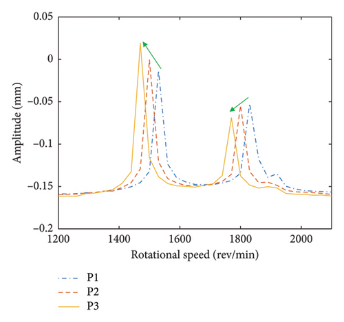
Figure 8 presents three-dimensional spectrums of the bolt connection under various positions of the eccentric disk. It is evident that the primary components are constituted by the LP and HP rotors rotational frequencies fL, fH, 2fL, and 2fH, as well as the superposition of fH and fL. In addition, it is observed that the position of the unbalanced disk does not significantly influence the frequency components.
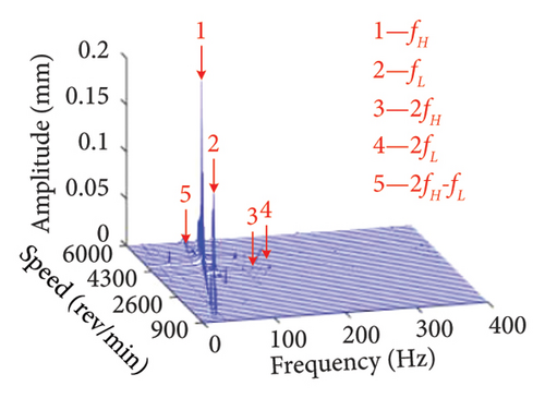
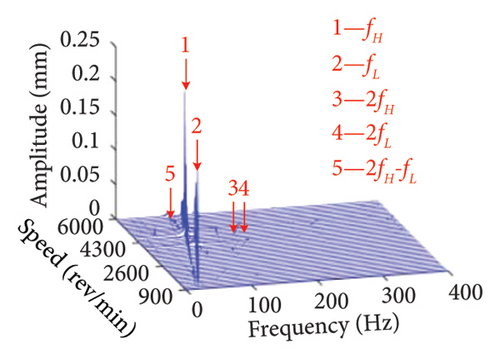
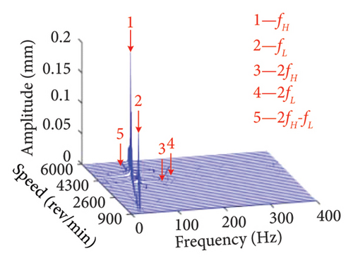
This is due to the fact that no new excitation frequencies are introduced, and the change in loading position caused by the change in unbalanced disk position does not cause the nonlinear vibration more violent.
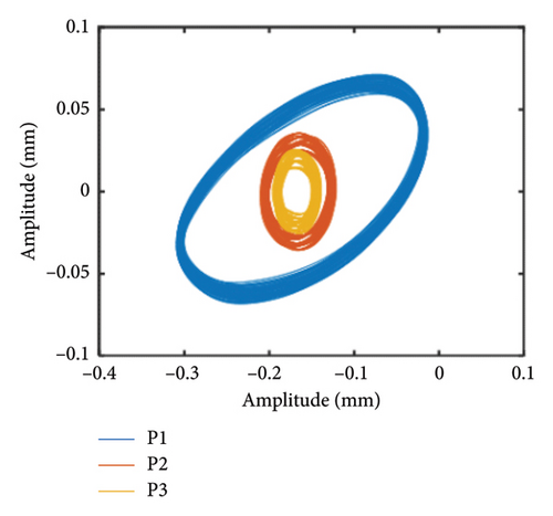
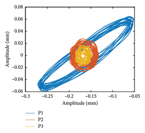
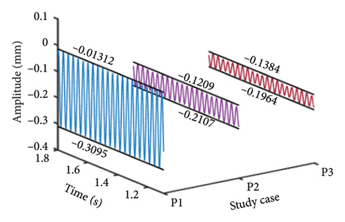
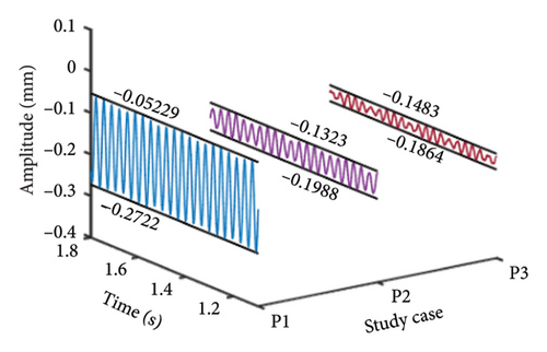
In order to further reveal the effect of the offset position of the unbalanced disk on system responses, the shaft obits and vibration responses at the bolt connection under ωH = 1530 rev/min and 1830 rev/min are obtained and shown in Figures 9 and 10, respectively. The shaft orbits and time-domain signals at the bolt connection show that as the offset disk moves closer to the HP rotor, the amplitude of the rotor decreases during both the 1st- and 2nd-order resonances. This suggests that adjusting the position of the unbalanced offset disk can effectively modulate the vibration response of the HP rotor. The underlying reason for this phenomenon is that altering the position of the unbalanced offset disk changes the mass distribution and rotor stiffness. This change leads to a critical speed shift. Consequently, the system response amplitude at the original critical speeds is reduced.
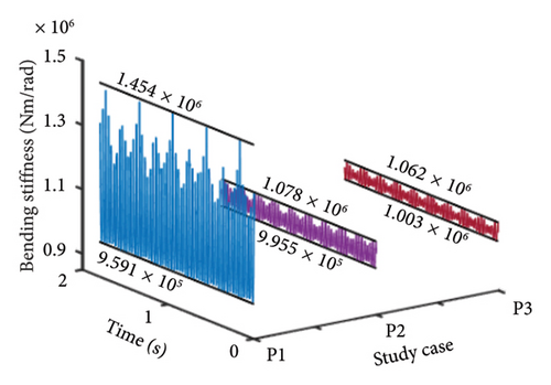
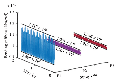
To further elucidate how the position of the unbalanced offset disk affects the bolt connection mechanical properties in the HP rotor, Figure 11 presents the bolt connection bending stiffness at different unbalanced offset disk positions, specifically at rotational speeds of ωH = 1530 and 1830 rev/min. The figure reveals that as the unbalanced disk moves closer to the HP rotor, the maximum bending stiffness of the bolt connection structure diminishes. This reduction suggests that the bending stiffness is more prone to transitioning into the second bending stage, primarily due to the increased vibration amplitude, consistent with the description in equation (15).
4.2. Effect of the Eccentricity of Disk 1
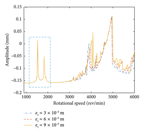
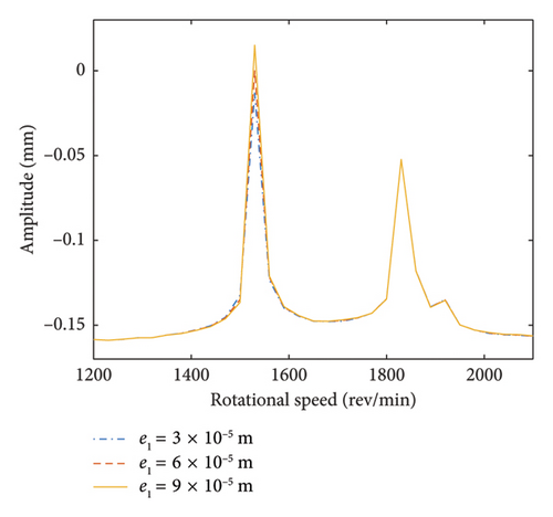
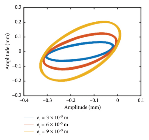
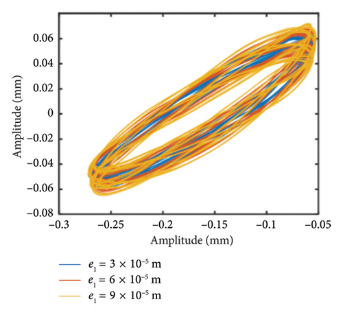
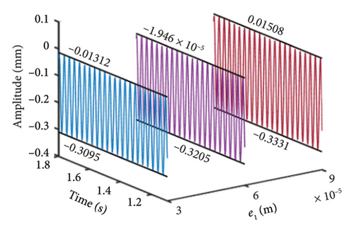
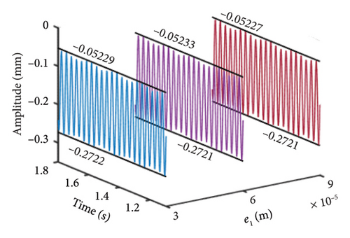
This section investigates the effect of the eccentricity of Disk 1 on the dynamic properties of the HP rotor and the mechanical properties of HP rotor bolt connection. The unbalanced disk is located at Node 3, and the rotational speed ratio ς is still defined as 1.2. In this study, the eccentricity of the unbalanced disk e1 is set to three different values: 3 × 10⁻⁵, 6 × 10⁻⁵, and 9 × 10⁻⁵ m. Through numerical integration, the responses of the bolt connection are further analyzed. Figure 12 illustrates the vibration amplitudes at the bolt connection for these different eccentricity values of the unbalanced disk. In Figure 12, the 1st- and 2nd-order resonances occur at about ωH = 1530 and 1830 rev/min, respectively. Moreover, it can be observed that the eccentricities of the unbalanced disk have no obvious effect on the 1st- and 2nd-order critical speeds. In order to further demonstrated that the vibration amplitudes of the HP rotor under different eccentricities of the unbalanced disk, the local amplitude–frequency curves within ωH = [1200∼2100] rev/min is obtained and shown in Figure 12(b). It can be clearly seen that the effect of increasing the eccentricity of the unbalanced disk on the vibration response of the dual-rotor system is notable. Specifically, as the eccentricity of the unbalanced disk increases, the vibration amplitude decreases when the system passes through the 1st-order critical speed. In contrast, there is no significant impact on the 2nd-order critical speed. This can be attributed to the fact that a higher eccentricity of the unbalanced disk results in a larger eccentric force acting on the rotor system. The intershaft bearing transmits this increased force, leading to a heightened response in the HP rotor. However, since the mass and stiffness of the rotor system remain largely unchanged with increasing eccentricity, the first two critical speeds are not significantly altered.
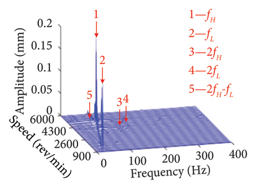
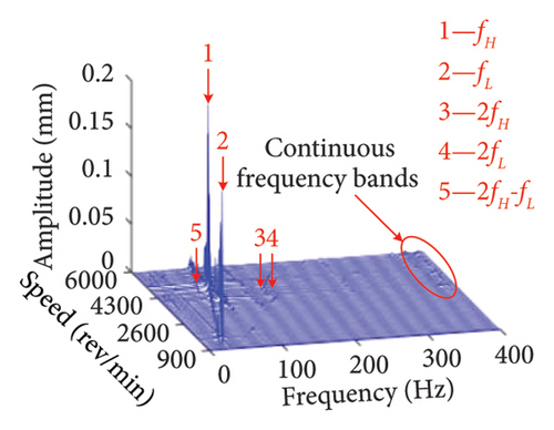
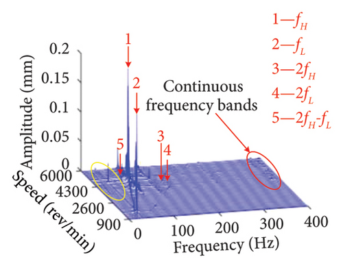
The three-dimensional spectrum plots of the bolt connection under eccentricities of e1 = 3 × 10⁻⁵, 6 × 10⁻⁵, and 9 × 10⁻⁵ m is given in Figure 13. It can be found that fL, fH, 2fL, 2fH, as well as the superposition of the corresponding times of fH and fL are the main frequency components under different eccentricities. However, as the eccentricity of the unbalanced disk increases, the continuous frequency bands with very small amplitudes appear around 400 Hz in the spectrum. This is due to the increased amplitude of the system caused by the increment of eccentricity make the bearing oscillation intensified. Consequently, the continuous frequency components are introduced.
In addition to the previous findings, Figures 14 and 15 depict the shaft orbits and vibration responses of the bolt connection for different eccentricities of the unbalanced disk at rotational speeds of ωH = 1530 rev/min and 1830 rev/min, respectively. The shaft orbits and time-domain waveforms reveal that the amplitude of the HP rotor increases with higher eccentricity values. However, the amplitude at the 2nd-order critical speed remains relatively unchanged. This suggests that the amplitude of the 1st-order critical speed is more sensitive to the eccentricity of the LP rotor’s unbalanced disk compared with the amplitude at the 2nd-order critical speed.
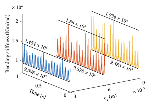
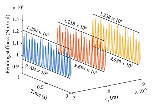
Furthermore, Figure 16 illustrates the bending stiffness of the bolt connection at ωH = 1530 and 1830 rev/min. It is observed that the maximum values of the bending stiffness at the 1st-order resonance increase significantly. This increase is attributed to the severe vibrations caused by the higher eccentricities of the unbalanced disk.
5. Experimental Study
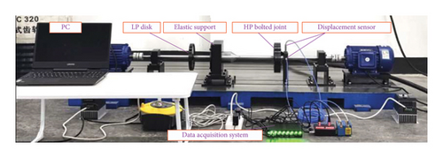
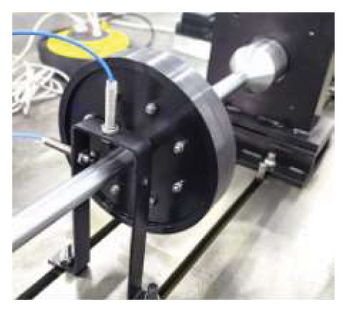
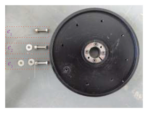
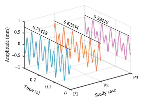
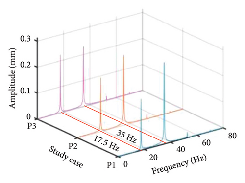
In the present section, time-domain response, spectra, and amplitude–frequency characteristics are reported to show a comparison with the experimental results by a bolt connection dual-rotor test rig for verifying the rationality and accuracy of the numerical simulation result. The test rig primary includes the HP rotor system, LP rotor system, and elastic support structure, where the bolt connection is set on the HP rotor system and the elastic support structure is used for vibration transmission; the detail is described in Figure 17(a). Among them, the vibration signal of bolt connection in x- and y-directions are collected by two displacement sensors and displayed on the PC after being processed by the data acquisition system, as shown in Figure 17(b). The LP disk is processed circumferentially several threaded holes used to install bolts and different numbers of shims achieving the eccentricity adjustment, as shown in Figure 17(d).
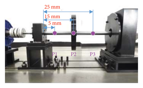
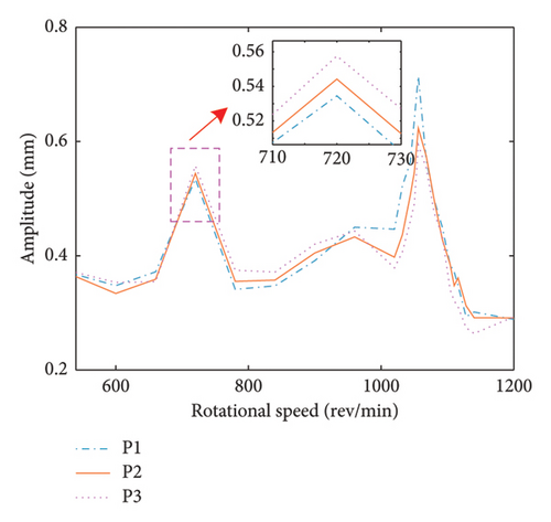
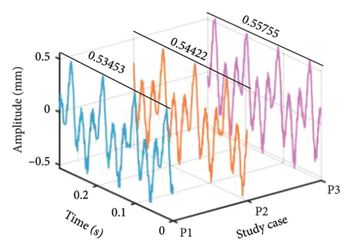
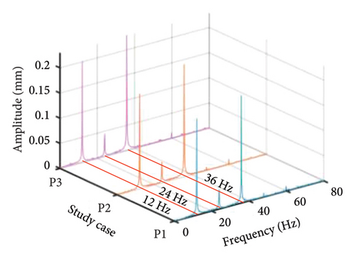
To explore the impact of disk offset on the dynamics of bolt connection dual rotor, three positions are chosen to carry out experiment as illustrated in P1, P2, and P3 in Figure 17(c). The comparison of amplitude–frequency diagram is acquired by collecting the vibration response under the above three position cases within ωH = ωL = [540∼1200] rev/min with the sampling frequency and rotational speed increment set as 1024 and 0.2 Hz, as demonstrated in Figure 18. It can be seen that the amplitude of the 1st-order critical speed increases while the amplitude of the 2nd-order critical speed decreases as the LP disk moves closer to HP rotor, which is consistent with numerical results. However, there are no significant changes emerged in the first- and second-order critical speeds, which is a gap with the numerical simulation. That is because the minimum rotational speed increment is so large that fails to catch the more precise critical speeds. Then, the dynamic response under different position cases is investigated to further demonstrate the variation trend about the amplitude of the first- and second-order critical speed, as depicted in Figure 19. The same behavior of the maximum response amplitude is observed in the amplitude–frequency diagram, where the amplitude at the 1st-order critical speed increases and the amplitude at the 2nd-order critical speed decreases as the LP disk moves closer to the HP rotor, confirming the validity of the numerical simulations. In addition, the frequency components of the system unchanged with variations in the disk offset.
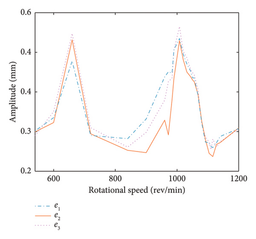
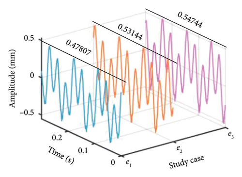
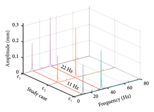
The effect of the eccentricity of the LP disk on the system nonlinear dynamic response is also explored using a similar analysis method, obtaining the comparison of the amplitude–frequency diagrams with different eccentricities, as shown in Figure 20, where e1 < e2 < e3. It can be found that all the 1st- and 2nd-order resonances occur at about ωH = ωL = 660 and 1008 rev/min under abovementioned three eccentricities cases. Besides, the corresponding amplitude of the first order critical speed is inversely proportional to the eccentricity of the LP disk. All these phenomena are consistent with the numerical analysis result and further demonstrated the accuracy of the present model and simulation result. It should be emphasized that the amplitude of the second-order critical speed emerges an elevated behavior under eccentricity case e3, leading to a distinction with the numerical result. That can be attributed to the strong nonlinearity of the test rig and numerous uncontrollable factors. Similarly, the comparison corresponding dynamic response and frequency spectrum of the 1st-order critical speed are acquired, as shown in Figure 21. It can be found that the maximum response amplitude of the rotor is directly proportional to the LP disk eccentricity, as well as the frequency components are the same, described as the fundamental frequency fr and second harmonic 2fr are dominant.
It should be stressed that the abovementioned result can be deemed a general conclusion, which is also appropriate for different bolt connection dual-rotor-bearing assemblies. It is attributed to the same results being obtained both in numerical and experimental analysis even though there exists some gap in the structural form, dimension parameter, and analytical environment between the numerical model and experiment rig.
6. Conclusions
- a.
The unbalanced disk position has a notable influence on the first two-order critical speeds and their associated vibration amplitudes. However, it does not significantly affect the rotor’s frequency components. As the offset disk moves closer to the HP rotor, the vibration amplitudes at both the 1st- and 2nd-order resonances decrease.
- b.
The maximum bending stiffness of the bolt connection structure diminishes as the unbalanced disk approaches the HP rotor. This suggests that the bending stiffness is more likely to transition into the second bending stage due to the increased vibration amplitude.
- c.
The eccentricity of the unbalanced disk in the LP rotor does not significantly impact the 1st- and 2nd-order critical speeds of the HP rotor. However, an increase in eccentricity leads to a reduction in vibration amplitude when the dual-rotor system crosses the 1st-order critical speed.
- d.
As the eccentricity of the unbalanced disk increases, continuous frequency bands with very small amplitudes appear in the HP rotor’s spectrum. In addition, the vibration amplitude of the HP rotor increases with higher eccentricity values. The bending stiffness at the 1st-order resonance also increases significantly with the increased eccentricity of the unbalanced disk in the LP rotor.
Nomenclature
-
- cs, cθ
-
- Lateral and rotation damping of the bolt connection disks
-
-
- Damping matrix of the bolt connection
-
- Cb
-
- Damping matrix of the beam element
-
- CL, CH
-
- Damping matrices of the LP and the HP rotors, respectively
-
- ei (i = 1, 2, 3, 4, 5)
-
- Eccentricities of disk i
-
- fi
-
- The contact force of the ith rolling ball and the raceway
-
- fn1, fn2
-
- The 1st and 2nd-resonant frequencies
-
- Fx, Fy
-
- Support forces acting on the rotor in the x- and y-directions
-
- FL, FH
-
- External force vectors of the LP and HP rotor
-
- Fb
-
- External force vector of the rotating shaft beam element
-
-
- Bolt connection gyroscopic matrix
-
- Gb
-
- Shaft beam element gyroscopic matrix
-
- GL, GH
-
- Gyroscopic matrices related to the LP and HP rotors
-
- Jdi (i = 1, 2, 3, 4, 5)
-
- Rotational inertia of the diameter of disk i
-
- Jpi (i = 1, 2, 3, 4, 5)
-
- Polar inertial moment of disk i
-
-
- Hertzian contact stiffness
-
- kθ
-
- Bending stiffness between the bolt connection disks
-
- kθ1
-
- First-stage bending stiffness between bolt connection disks
-
- kθ2
-
- Second-stage bending stiffness between bolt connection disks
-
- ks
-
- Transverse stiffness between bolt connection disks
-
-
- Stiffness matrix for the bolt connection
-
- Kb
-
- Stiffness matrix for the rotating shaft beam element
-
- KL
-
- Matrix of stiffness associated with the LP rotor
-
- KH
-
- Matrix of stiffness associated with the HP rotor
-
- mdi (i = 1, 2, 3, 4, 5)
-
- Mass of the disk i
-
- Mb
-
- Mass matrix associated with the rotating shaft beam element
-
- ML, MH
-
- LP and HP rotor mass matrices
-
-
- Bolt connection mass matrix
-
- Nb
-
- Total number of balls
-
- R, r
-
- Radii (inner and outer) of the bearing
-
- qJ
-
- Displacement vector associated with the bolt connection
-
- qb
-
- Displacement vector associated with the rotating shaft beam element
-
- qL, qH
-
- LP and HP rotor displacement vectors
-
-
- Bolt connection force vector
-
- (i = 1, 2)
-
- Lateral displacement of beam element nodes in the x-direction
-
- UJ
-
- Potential energy associated with the bolt connection
-
- vcage
-
- Tangent velocity associated with the bearing cage
-
- vi, vo
-
- Tangent velocity of bearing inner and outer races
-
- (i = 1, 2)
-
- Lateral displacement along the y-axis for beam element node
-
- xi (i = 1, 2, 3, 4, 5)
-
- Lateral displacement along the x-axis for disk i
-
- yi (i = 1, 2, 3, 4, 5)
-
- Lateral displacement along the y-axis for disk i
Greek letters
-
- ωi, ωo
-
- Angular velocity of the inner and outer races
-
- ωH, ωL
-
- Angular velocity of the HP and LP rotors
-
- θi
-
- The angle of the ith ball at time instant t
-
- θxi, θyi
-
- Rotation angles for disk i in the x- and y-directions
-
- (i = 1, 2)
-
- Rotation angle of beam element nodes about the x-axis
-
- (i = 1, 2)
-
- Angle of beam element nodes about the y-axis
-
- ωcage
-
- Rotational speed of the cage
-
- γ0
-
- Bearing radial clearance
-
- δi
-
- Normal deformation at the position of the ith rolling ball
-
- ξ1, ξ2
-
- Modal damping ratios
-
- Φ
-
- Relative angle of the bolt connection
-
- Φ0
-
- Relative angle while the external moment overcomes preload
Conflicts of Interest
The authors declare no conflicts of interest.
Author Contributions
Chuanmei Wen: software, writing the original draft, and funding acquisition. Tianliang Long: conceptualization. Xingliang Cai: reviewing and editing. Bing Li: conceptualization and formal analysis. Yuqi Li: data curation, funding acquisition, and project administration.
Funding
This research was supported by the National Natural Science Foundation of China under Grant no. 52305098, Guangxi Natural Science Foundation under Grant nos. 2024GXNSFBA010286, 2022GXNSFBA035488, and 2022GXNSFAA035550, National Natural Science Foundation of China under Grant no. 12362007, Science and Technology Project of Guangxi under Grant nos. GK AD22080042 and GK AD23026064, Construction of Guangxi Engineering Machinery LowCarbon Digital Intelligence Technology Innovation Center under Grant no. 2023PRJ0101, and Doctoral foundation of Guangxi University of Science and Technology under Grant no. XKB 21Z64.
Acknowledgments
Chuanmei Wen acknowledges the support of Guangxi University of Science and Technology, China.
Appendix A: Expressions for the Timoshenko Beam Element and External Force Vector of the Rotor
Open Research
Data Availability Statement
The data used to support the findings of this study are available upon reasonable request.


