Prediction Model of Impact Vibration Strength Under Explosion
Abstract
Aiming at the attenuation law of shock vibration acceleration of bulkhead structure under the action of internal explosion load, the model shock vibration test of internal explosion chamber was carried out to analyze the impact environment of different positions of bulkhead structure. The attenuation law of wall vibration intensity under internal explosion environment is studied. The simulation method verified by the experiment was used to simulate the implosion process of the cabin model. The implosion simulation calculation was carried out by setting different charge amounts. The observation points were arranged on the bulkhead, and the acceleration curves at the measurement points were extracted to record the peak acceleration. Based on the regression analysis of the simulation data, the prediction model of the peak vibration acceleration of the cabin bulkhead structure in the environment of internal explosion is established. It has important reference value for damage assessment of personnel and electronic equipment in internal explosion chamber and protection design of ship.
1. Introduction
With the continuous development of science and technology, electronic equipment is gradually applied in various fields of national defense. In modern war, electronic equipment is the core of modern weapon system [1–3]. Electronic equipment is usually located in the ship cabin, which is not easy to be directly damaged by fragmentation and shock wave caused by ammunition explosion, and the shock vibration caused by explosion will bring great harm to electronic equipment, resulting in its function failure. The damage of electronic equipment is mainly related to the peak of shock vibration acceleration, shock vibration frequency, shock vibration number, and other factors [4–6]. The short peak action time of shock and vibration acceleration is the main cause of equipment damage, especially radar equipment and electronic control system. Once these important functional chambers are damaged, the ship’s movement and combat ability will be seriously affected [7].
During World War II, the United States Navy suffered heavy losses because it did not pay attention to equipment damage caused by ship impact [8]. After the end of World War II, the US Army recycled part of the damaged ships and carried out a large number of real ship shock resistance tests, during which a large amount of test experience and data were accumulated. At present, scholars at home and abroad have done a lot of research on the prediction methods of ship impact environment and obtained a series of empirical formulas for ship impact environment prediction in different situations, and some achievements have been made. Chen and Zeng [9] and Fang [10] analyzed the impact environment at the position of the bottom cabin on the basis of fully investigating the impact environment test data and concluded the calculation model that can be used to predict the impact environment of ships by fitting the test data. Niangang [11], Ji et al. [12], and Cui et al. [13] conducted an experimental study on the vibration characteristics of internal explosion shock with explosive vessels and proposed a method for predicting structural vibration intensity suitable for engineering application from two aspects of linear regression and neural network. Liu [14] introduced the least square method in mathematics in the process of processing the ship impact environment database and provided the engineering prediction method of ship impact environment under various circumstances. Liu et al. [15] proposed a prediction model of vibration response considering the medium conditions between the explosion source and the structure. Lin [16] established a ship real scale model based on numerical simulation software. With the antiship missile implosion as the research background, based on the numerical simulation results and on the basis of the peak acceleration data of a large number of positions on the deck, the function relationship between the peak acceleration and the propagation distance and the dose was summarized. In terms of the damage mode prediction model of explosion load, Jiao et al. [17] deduced the dimensionless damage number of the multichamber structure under implosion through dimensional analysis and gave the rapid damage prediction method of multichamber structure under implosion. Yao [18] proposed a new dimensionless number for the response of the explosive structure inside the box structure, which is positively correlated with the explosive energy and negatively correlated with the resistance of the structure itself and the volume of the loaded wall. Ying et al. [19] carried out the impact response experiment of the cabin explosion to the target plate under eight working conditions, compared and analyzed the plastic deformation of the target plate under different explosion distances, and obtained the typical failure mode of the fixed square plate under the action of the cabin explosion. Xie [20] conducted research on the environmental factors affecting the propagation of explosion shockwaves in plateau environments, revealing the mechanism of explosion shockwave propagation at high altitudes. The study found that temperature and humidity have relatively minor impacts on shock vibration in lower altitude environments.
At present, the research on ship impact environment mainly focuses on underwater explosion and large yield warhead such as antiship missile. There is still a lack of systematic research on the propagation law of the impact vibration intensity generated by the internal explosion of conventional shells in the cabin structure. With more and more high requirement on the prediction accuracy of damage effect in the chamber of semiarmor-piercing bomb, it is imperative to establish the damage probability calculation method of impact vibration to personnel and equipment in the chamber.
In this paper, an internal explosion shock vibration test with an adjacent chamber is carried out, and the attenuation law of the peak vibration acceleration of the internal explosion chamber structure is obtained. A multicabin numerical simulation model was established, and a large number of simulation calculations were carried out by changing the mass of explosives. The vibration at typical positions of the cabin wall was monitored, and the attenuation law of the peak vibration acceleration with the mass of charge, the distance between the center of detonation and across the transverse bulkhead was obtained. Through the regression analysis of the simulation data, the prediction model of the peak vibration acceleration in the cabin under the environment of internal explosion was established. It lays the foundation for damage assessment of the equipment in the environment of shock and vibration.
2. Double Chamber Model Blowout Test
2.1. Double Chamber Test Facility
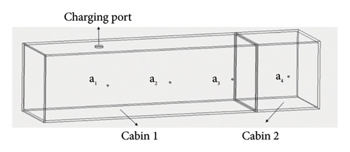
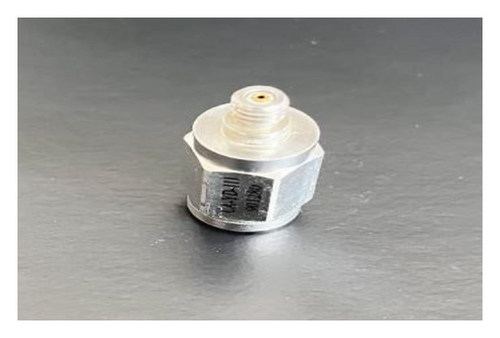
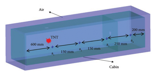
In this experiment, the double-cabin model was adopted, and the adjacent cabin environment was constructed by splints in the middle of the double-cabin model. The model size of the double cabin is a cuboid of 1350 × 400 × 400 mm. Here, it is assumed that the cabin where the explosive occurs is cabin 1, and the adjacent cabin is cabin 2. The length of cabin 1 is 1350 mm, the length of cabin 2 is 400 mm, the thickness of bulkhead is 10 mm, and the thickness of bulkhead is 5 mm. The explosives used in the test were 10 and 20 g and were hoisted from the pressure relief port of the cabin model into the center position in the vertical direction. During the test, four groups of acceleration sensors were arranged along the longitudinal direction of the bulkhead with equal spacing on the surface of the casing. The acceleration sensors adopted the model CA-YD-111 produced by Jiangsu Union Energy Company. The sensors were arranged with equal spacing, with a spacing of 150 mm, and the acceleration sensors were placed perpendicular to the bulkhead to measure the transverse impact of the explosion load on the casing. Among them, a1, a2, and a3 are arranged in the explosion chamber, a3 is located near the junction of the two chambers, and a4 is placed in the center of the adjacent bulkhead surface for monitoring the vibration environment of the adjacent chamber. Specifically, a1 is located 600 mm from the left side of the cabin 1, with a1, a2, and a3 being spaced 150 mm apart from each other, and a3 being 250 mm away from a4. The structural diagram of cabin model vibration test is shown in Figure 1, and the physical diagram of acceleration sensor and the installation diagram of cabin model test are shown in Figure 2.

2.2. Analysis of Test Results
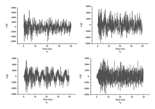
After the internal explosion test, by sorting out the test data and analyzing the explosion data of the same measuring point with different charge masses, it can be seen that the peak value of vibration acceleration increases gradually with the increase of the charge amount, showing a certain similarity. For the acceleration time history curve of each measuring point under the same dosage, the measuring point a1 is closest to the detonation source and the shock wave arrives first, so the acceleration of the measuring point a1 is the first to reach the peak in both groups of tests. The peak acceleration of each measuring point in 10 g dose test is 8300 g, and the peak acceleration of each measuring point in 20 g dose test is 11500 g. Because the measuring point a2 is slightly farther from the detonation source, the peak value of vibration acceleration decreases, and the corresponding peak time is slightly later. Although the measuring point a3 is far away from a2, the peak acceleration does not attenuate, but increases. As can be seen from the data at measuring point a4, the peak acceleration decreases significantly as a result of crossing a transverse bulkhead. Under the two groups of test conditions, the acceleration time history curves of the four measuring points on the cabin wall are shown in Figures 3 and 4.
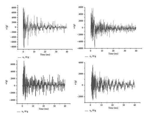
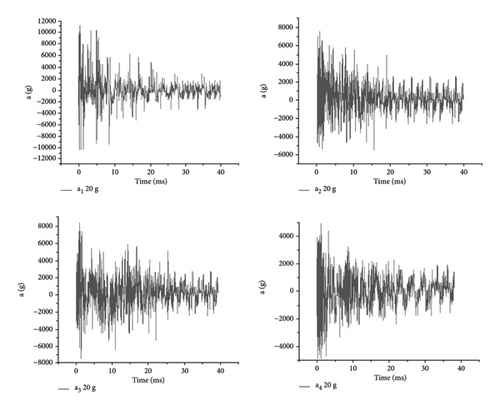
It can be seen from the test acceleration time history curve of each measuring point on the bulkhead of box-type structure that the peak value of vibration acceleration is not only related to the mass of explosive and the distance between the measuring point and the detonation source but also shows more intense vibration at the corner of the cabin structure. After crossing the transverse cabin wall, the peak value of vibration acceleration of the measuring point decreases rapidly, which shows the complexity of the impact vibration environment of the cabin under the condition of implosion. Limited by test conditions, it is impossible to conduct a large number of test studies. Next, numerical simulation will be used to explore the attenuation law of vibration acceleration peak of internal explosion bulkhead structure.
3. Numerical Simulation Model
3.1. Simulation Establishment and Verification
The finite element model includes cabin structure, air domain, and explosives. The cabin structure model adopts 4-node shell element, while the air and explosives finite element model adopts 8-node body element. Considering the large deformation of the structure, in order to ensure that the deformed structure can still be affected by the explosion load, the cuboid air domain is established to completely cover the cabin body. To construct a finite element geometric model utilizing AUTODYN software, the TNT material is characterized by the employment of the Lagrangian formulation, whereas the air medium is described through the application of the Eulerian formulation. Appropriate material properties corresponding to these formulations are chosen from the integrated material database. The bulkhead model is discretized using shell elements featuring a mesh resolution of 5 mm. The explosion shockwave and detonation products are permitted to propagate freely within the gaseous computational domain. At the stationary end of the bulkhead model, fixed boundary conditions are imposed, while rigid boundary conditions are enforced on the air within the cabin. Outflow boundary conditions are specified for the air domains situated at both extremities. The numerical simulations are conducted using a fluid-structure interaction (FSI) algorithm. The structure size of the simulation model remained the same as that of the test model, as shown in Figure 5.
| Parameters | ρ (g·cm−3) | γ | e (kJ·m−3) |
|---|---|---|---|
| Value | 0.001225 | 1.4 | 206,800 |
In equation (1), the air density ρ is 1.225 kg/m3, the internal energy per unit mass of air e is 2.068 × 10⁵ J/kg, and the adiabatic exponent γ is 1.4.
| Parameters | ρ (g·cm−3) | A (MPa) | B (MPa) | R1 | R2 | ϖ | D(m·s−1) | ρcj(MPa) | E(kJ·m−3) |
|---|---|---|---|---|---|---|---|---|---|
| Value | 1.63 | 374,000 | 3750 | 4.15 | 0.09 | 0.35 | 6930 | 21,000 | 7.0e6 |
Q235 steel was adopted as the bulkhead material, the chosen strength model was Johnson-Cook. The material parameters were shown in Table 3.
| Parameters | ρ (g·cm−3) | A(MPa) | B(MPa) | n | c | m | Tm(K) |
|---|---|---|---|---|---|---|---|
| Value | 7.85 | 249.2 | 889 | 0.746 | 0.058 | 0.96 | 1793 |
The structure size and explosive arrangement of the numerical calculation model of the cabin are consistent with the test conditions. A threshold measuring point is set at the same position of the structural wall of the cabin as the test to record the vibration attenuation law of the cabin wall. Taking the mass condition of 10 g explosive in the test as a typical condition, the numerical calculation results of vibration acceleration at each measuring point of bulkhead are shown in Figure 6.
The peak acceleration at the transverse typical measuring point of the explosion chamber is shown in the figure above. It can be seen that with the increase of the distance from the explosion point, the peak acceleration at the typical measuring point gradually moves backward, which accords with the attenuation law of shock wave overpressure in the chamber. Near the bulkhead, the peak acceleration at the measuring point increases. This is due to the reflection of the shock wave near the bulkhead and the convergence of the shock wave at the corner of the bulkhead, where the impact environment is more severe. The peak acceleration continues at a high amplitude for a period of time, and the attenuation is slow and finally tends to be stable. After crossing a bulkhead, the peak acceleration attenuates rapidly, so it can be considered that the presence of bulkhead has a great influence on vibration intensity. The peak acceleration of impact vibration obtained by numerical calculation is read and recorded for comparison and analysis with the test data, and the results are shown in Table 4.
| Mass (g) | Acceleration | |||||||
|---|---|---|---|---|---|---|---|---|
| a1 (g) | a2 (g) | a3 (g) | a4 (g) | |||||
| Test | Simulation | Test | Simulation | Test | Simulation | Test | Simulation | |
| 10 | 8300 | 7100 | 6450 | 5400 | 7000 | 5980 | 3500 | 2980 |
| 20 | 11,500 | 9960 | 7800 | 6750 | 8700 | 7560 | 4900 | 4230 |
By comparing the test data of cabin structure vibration acceleration with the simulation results in the table above, it can be seen that the multimaterial fluid-structure coupling algorithm using AUTODYN software can accurately reflect the response of the structure and can simulate and calculate the interaction between the load and the structure during the explosion in the cabin. Then, using the numerical calculation method verified by experiments, the impact vibration response law of the bulkhead structure of a typical ship’s cabin implosion is studied.
3.2. Prediction Model of Vibration Intensity
The damage to shipborne electronic equipment is mainly caused by the impact acceleration within the cabin, so it is of great significance to study the distribution law of impact acceleration for the protection of electronic equipment in the cabin. This section mainly analyzes the distribution characteristics of impact acceleration along the cabin wall, sets measuring points with different distances on the bulkhead, processes the data at the measuring points, draws the curve of impact acceleration changing with distance, and obtains the propagation law of impact acceleration inside the cabin. According to the attack characteristics and flight trajectory of naval projectile charge and considering the influence of adjacent compartments on the vibration response distribution law of explosion chamber, this section chooses the built compartments on typical ships as the research object and evenly sets observation points on the explosion chamber and adjacent bulkhead surface of the structure. The cabin model is composed of single cabin structure. According to the typical cabin size of conventional destroyer, the size of single cabin is 4.0 × 2.0 × 2.5 m. Based on the investigation of the equivalent TNT equivalent range of the current mainstream ship projectile charge, the explosive is placed in the geometric center of the explosion chamber, and the charge volume ranging from 0.25 to 6 kg is selected for numerical calculation. The observation point is evenly arranged at the bulkhead position with equal distance.
The propagation law of the peak impact acceleration in the cabin is analyzed, and the formula of the influence of drug dosage and distance is obtained, which can effectively predict the peak acceleration of any point in the cabin wall and provide some reference for the subsequent study on the damage assessment of the carrier electronic equipment.
4. Conclusion
- (1)
The impact vibration test of the internal explosion chamber was carried out, and the numerical simulation model was verified on the basis of the acceleration test data of the internal explosion impact vibration.
- (2)
The attenuation law of the peak acceleration at the wall surface of cabin structure in the process of implosion is studied, and the relationship between the peak acceleration of shock vibration and distance, dosage, and bulkhead is analyzed.
- (3)
A large number of numerical simulation calculation conditions are designed by changing the mass of explosive. Based on the numerical calculation results, an empirical formula is given to quickly calculate the peak acceleration of bulkhead.
- (4)
Based on numerical calculation results, an empirical formula for rapidly calculating the peak acceleration of bulkheads under internal explosion loading is proposed. Utilizing this formula, the bulkhead acceleration can be swiftly estimated, revealing the dynamic response mechanisms of specific bulkhead structures under explosive loading, including deformation patterns, failure mechanisms, and energy absorption characteristics. These findings deepen our understanding of the blast-resistance performance of bulkhead structures and provide crucial theoretical support for improving and optimizing bulkhead designs. The research outcomes can be applied in industries such as shipbuilding to optimize bulkhead structures and damage assessment methods. Future work can further explore explosion simulation techniques and experimental methods to develop more intelligent and efficient early warning systems and emergency response mechanisms to address potential explosion threats.
Conflicts of Interest
The authors declare no conflicts of interest.
Author Contributions
All authors contributed to the study conception and design. The first draft of the manuscript was written by Qing-Hua Chen, and data collection and analysis were performed by Yue-Qiu Jiang. All authors read and approved the final manuscript.
Funding
This work was supported by Liaoning Provincial Subsidy for Basic Scientific Research Projects of Undergraduate Colleges Affiliated With Liaoning Province (Grant No. LJ2-124-1014-4023); Shenyang University of Science and Technology Research Support Program for High-Level Talent Introduction Project (Grant No. 1010-14700-1253); and Shenyang Ligong University (Grant No. SYLUXM202108).
Open Research
Data Availability Statement
The datasets supporting the conclusions of this article are available from the corresponding authors upon request.


