An Innovative Semiactive Rolling Tuned Mass Damper for Structural Vibration Mitigation
Abstract
This study introduces a novel semiactive rolling tuned mass damper (SARTMD) developed to mitigate structural vibrations more efficiently than conventional tuned mass dampers (TMDs), with a primary objective of significantly reducing absorber mass without compromising performance. The proposed device combines translational and rotational motions, featuring two key innovations: (i) an umbrella-like mechanism that dynamically adjusts the moment of inertia by varying the radius of a secondary mass, allowing real-time frequency tuning, and (ii) a planetary gearbox that transmits the rotation of a primary rolling mass to the secondary mass, increasing its angular velocity. This configuration enables substantial mass ratio reduction while maintaining high control effectiveness. A numerical model of a single-degree-of-freedom (SDOF) structure subjected to harmonic excitation from rotating machinery is developed to evaluate the system’s performance. A short-time Fourier transform (STFT)-based control algorithm is implemented to continuously match the SARTMD’s natural frequency with the dominant excitation frequency. Parametric studies are conducted to identify optimal ranges for the system’s parameters. Simulation results show that, compared to an uncontrolled system, the SARTMD reduces the peak displacement, velocity, and acceleration by 76.4%, 77.4%, and 77.9%, respectively, and lowers RMS responses by over 91%. Compared to a traditional TMD, it achieves 66% greater peak displacement reduction while using only 30% of the mass. Robustness analysis confirms that the system maintains effective performance under up to 30% frequency detuning. These results confirm that the SARTMD offers a lightweight, adaptive, and highly efficient alternative for structural vibration mitigation in applications with space or weight constraints.
1. Introduction
Controlling vibrations in structures and dynamic systems is a critical engineering challenge, particularly under dynamic loads such as earthquakes, wind, and human-induced forces. Similar issues occur in vehicle suspension systems, where vibration control is essential for stability and performance [1, 2]. To enhance damping, various vibration control devices have been developed and implemented. Structural control strategies are typically classified as passive, active, hybrid, or semiactive. Semiactive systems evolve from passive ones, enabling real-time property adjustments. They offer benefits comparable to active systems [3] but with lower power demands and without injecting energy into the system, thus avoiding destabilization risks [4].
Mass vibration absorbers such as active tuned mass dampers (ATMDs) and semiactive tuned mass dampers (SATMDs) play a crucial role in the vibration control of structures across various engineering fields. Both are developed from the tuned mass dampers (TMDs), their passive counterpart known for their simplicity, efficiency, and reliability in suppressing structural vibrations—a concept first introduced by Frahm [5]. While TMDs are effective within a narrow frequency band, their limitations including sensitivity to detuning have led to the development of ATMDs [6, 7] and SATMDs [8]. Their use to overcome these challenges and for controlling responses in tall buildings under mainshock-aftershock was investigated by [9].
SATMDs are semiactive counterparts of TMDs, offering the ability to fine-tune damping [10] and/or stiffness properties [11–13]. As one of the early contributions, Walsh and Lamancusa [14] introduced a variable stiffness mechanism using leaf springs and a stepper motor to adjust spring spacing. In 2010, Ghorbani-Tanha [15] designed a system with springs arranged in a circular pattern. This design allows for the adjustment of the device’s effective stiffness by rotating the mounts of the springs, thereby altering its configuration and stiffness. In another study, in 2011 Ghorbani-Tanha et al. [16] developed a semiactive variable stiffness (SAVS) device in which the stiffness is altered by rotating a beam-like device. Moreover, tuning can be performed by adjustments in the properties of the device. For instance, innovations in pendulum-tuned mass dampers (PTMD) include changes in the pendulum’s length [17, 18], or as recently investigated by [19] in 2023, alterations can be in the PTMD’s orientation.
Indeed, mass is another adjustable property of SATMDs that can be changed for real-time readjustment of the absorbers [20, 21]. However, it is important to note that altering mass-related characteristics in translational systems is generally more complex compared to adjusting damping or stiffness [22]. However, in rotary systems, the focus shifts to the mass moment of inertia (MMI), which can be altered by adjusting the distance between rotating masses and their axis, as well as modifying mass, offering an enhanced control mechanism. Despite their potential benefits, few research studies have been conducted on such systems. Mohammadi-Ghazi et al. [22] proposed an adaptive configuration tuned mass damper (ACTMD) to suppress both rotational and translational vibrations in structures. The ACTMD adjusts its configuration in real-time to retune with the instantaneous excitation frequency by changing the position of its moving parts and altering the MMI. In 2020, Shakib et al. [23] introduced the spindle adaptive tuned vibration absorber (SATVA), a semiactive device capable of attenuating vibrations in host systems by altering its MMI via movable rotating supports, resulting in adjustable natural frequencies with low power consumption. In a recent study (2025) [24], a rolling tuned mass damper (RTMD) was introduced as an alternative to conventional TMDs, designed to exploit pure rolling motion to enhance energy dissipation and inertial effectiveness. The results demonstrate that the RTMD provides superior displacement and acceleration reduction compared to classical TMDs, particularly in stiffer structures. However, the system is limited to purely rotational motion and lacks both translational motion and tunable parameters.
Inerter-based vibration absorbers (IBVAs) represent a new generation of TMDs first introduced by Smith [25]. These absorbers use a mechanical device known as an inerter to counteract and dampen vibrations by providing an opposite phase force to the applied motion [26]. Building on this concept, a novel design, the tuned tandem mass dampers-inerters (TTMDI), was proposed by [27]. The TTMDI integrates two inerters to achieve high effectiveness and broad frequency spacing. When tested on a single-degree-of-freedom (SDOF) structure under random Gaussian white noise base excitations, the results demonstrated that TTMDI outperforms traditional TMD in terms of performance. Further extending the TTMDI concept, a recent study by [28] introduced pendulum-type TTMDIs for crosswind response control in super-tall buildings. This approach integrates pendulum dynamics with the TTMDI, improving the mitigation of wind-induced vibrations in such large structures. Additionally, to enhance the performance of TTMDIs in seismic vibration control [29], high-robustness eddy current TTMDIs were introduced, which offer greater robustness in mitigating seismic vibrations.
Despite the proven effectiveness of IBVAs, their reliance on precise tuning for optimal performance and susceptibility to detuning remain significant challenges. To address these weaknesses, Brzeski et al. [30, 31] proposed utilizing a continuously variable transmission (CVT) with a gear-ratio control system to equip a device with an inerter. This approach was later validated by Ebrahimnejad and Samani [26] in 2020, who demonstrated the effectiveness of the device for beam-like structures and determined the optimal parameters for vibration absorption. More recently, a new configuration of multiple tuned mass damper inerters (MTMDIs) has been proposed, featuring an optimized arrangement of TMDIs distributed across the building [32]. In this design, each inerter’s second terminal is linked to the mass of the TMD directly below, forming a sequential system that improves energy dissipation and accommodates real-world installation constraints.
In general, masses in typical IBVAs or SATMDs are designed to undergo either rotational or translational motion, but not both. However, this study introduces a novel concept that integrates these two types of motion to reduce the required absorber mass while maintaining effective vibration suppression. Based on this concept, we propose a new type of damper called the semiactive rolling tuned mass damper (SARTMD). This device incorporates a mechanically adaptive secondary mass whose radius is continuously adjusted through an umbrella-inspired mechanism, enabling real-time variation of the MMI. This radius change directly influences the system’s natural frequency, providing a semiactive means of frequency tuning. To amplify the rotational speed of the secondary mass and further reduce the mass ratio, the primary rolling mass is connected via a planetary gearbox, increasing the relative angular velocity without additional energy input. When compared to traditional SATMDs, the SARTMD achieves a lower mass ratio while combining key features of IBVAs and SATMDs. The primary novelty of this system lies in its dual adaptation: combining rolling-translational motion for inertial transformation and geometric reconfiguration of the secondary mass for tunable dynamics. To establish the viability of the concept, the governing equations of motion for the SARTMD are derived, and a detailed parametric analysis is conducted to determine optimal values for system parameters. A numerical case study is presented to assess the performance of the proposed configuration. Finally, time-domain simulations are used to evaluate the SARTMD’s effectiveness under harmonic excitation and to benchmark its performance against that of a conventional TMD. Results confirm that the SARTMD achieves superior vibration mitigation with a significantly lower absorber mass, validating its potential for applications where both dynamic performance and mass efficiency are critical.
The remainder of this paper is organized as follows: Section 2 presents the governing equations for a rolling SDOF system. Section 3 details the SARTMD’s mechanical design, including its adaptive mechanism and planetary gearbox. Section 4 provides a parametric study of key design variables. Section 5 describes the structural model, and Section 6 evaluates the SARTMD’s performance through numerical simulations. Section 7 examines robustness under off-tuning, and Section 8 concludes with key findings and future directions.
2. Rolling SDOF Systems Without Slipping
The foundation of the proposed mass damper relies on a rolling SDOF mass-damper-spring system as shown in Figure 1. To establish the theoretical framework and highlight the novelty of the proposed SARTMD, first the equation of motion governing a rolling SDOF system without slipping is derived.
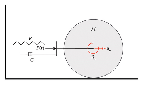
As previously discussed, the innovation in the proposed mass damper lies in achieving a reduced mass ratio between the SARTMD’s and the structure’s mass. A comparison of equation (7) with the governing equation of motions of translational SDOF systems reveals that while keeping the system properties constant, i.e. fixed mass, damping, and stiffness, the dynamic effective mass for an SDOF system undergoing rolling motion is 50 percent higher than when the mass is restricted to translational motion. The implementation of mass dampers presents challenges and limitations, particularly due to the significant mass they introduce to structures. However, by accounting for the effects of rolling motion, it becomes feasible to substantially decrease the mass ratio between the mass damper and the structure. In simpler terms, to tune the natural frequency of the mass damper to a specific frequency given a certain stiffness and damping, incorporating a rolling degree of freedom in the mass allows for achieving this frequency with a lower mass (two-thirds of the mass of the system with constrained translational motion).
3. The Proposed SARTMD
3.1. SARTMD’s Equation of Motion
The proposed SARTMD is illustrated in Figure 2. This innovative device comprises several components, including a gear with mass M1 that undergoes rotation on a fixed rack (R), a planetary gearbox (G), and a rotating flywheel with mass M2 equipped with an umbrella-like expanding mechanism. The rotational motion of mass M1 is transmitted to mass M2 through the utilization of the planetary gearbox. Detailed explanations of the planetary gearbox and the umbrella-like expanding mechanism are provided in Sections 4 and 5, respectively.
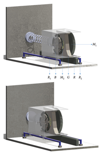
The entire assembly of the masses and gearbox are enclosed within a box (B) which is further constrained to translational motion along a pair of rails (R1 and R2). The rack (R) is built fixed beneath the box, and the mass M1 rotates on it as previously mentioned. Notably, the rotating mass M2 is designed to have no contact with any surface and is solely connected to the box (B) via a bearing, thereby allowing unrestricted rotational freedom. This box (B) is connected to the structure through a spring with stiffness K. Additionally, the system possesses an inherent damping coefficient C which arises from sliding, rotation, and all other motions. The components of the gearbox are shown in Figure 3.
Therefore, by altering the β(t), SARTMD’s natural frequency can be adapted in real-time. It is important to note that the gear ratio (rg) should exceed one, a condition met when employing a gearbox with a fixed ring gear (as seen in configuration A of Table 1). If rg equals one, it effectively means that no gearbox is in use, resembling a direct drive scenario where θ2 = θ1.
| Configurations | A | B | C | D |
|---|---|---|---|---|
| Fixed part | Ring gear | Carrier | Sun gear | |
| Driver part | Sun gear | Sun gear | Ring gear | Direct drive |
| Driven part | Carrier | Ring gear | Carrier | |
| Gear ratio | 2 < rg < ∞ | −∞ < rg < −1 | 1 < rg < 2 | rg = 1 |
3.2. Planetary Gearbox
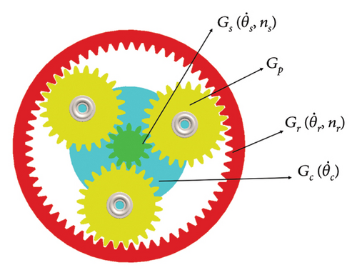
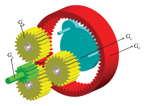
As mentioned, in the suggested SARTMD, rolling mass motion has been used for vibration control. As elaborated in Section 3.1, transmitting the rotation of the primary mass to a secondary mass with an augmented rotational speed can further decrease the mass ratio, which is performed using a gearbox. The suggested SARTMD utilizes a planetary gearbox due to its high efficiency and compact installation space requirements when compared to other types of gearboxes. This type of gearbox finds wide application across various industries and for different purposes. As shown in Figure 3, the planetary gearbox consists of two or more gears known as planetary gears (Gear Gp) which rotate around a central gear called the sun gear (Gear Gs) about an axis. The planetary gears are typically mounted on an arm or a movable carrier (member Gc), and the entire system is surrounded by a ring gear (Gear Gr).
For a planetary gearbox, four configurations are possible that are summarized in Table 1.
3.3. Expansion Mechanism
The mechanism’s foundation relies on adjusting the radius of a secondary mass disk. By varying the radius of the second disk as a time-dependent parameter, the system’s frequency can be derived according to equation (15). For optimal system performance, it is essential that the frequency varies smoothly within a specific continuous range. In other words, the disk radius should be modified by the proposed umbrella-like mechanism in a continuous, nondisruptive manner. The components of this mechanism, shown in Figure 4, include ring B, which is connected to arms C and moves along the central rod D, causing a continuous radial displacement of the masses A around the disk. Figure 4 illustrates two configurations: a closed state and an open state. This radial displacement of the masses A leads to a variation in the moment of inertia of the disk over time. With the specific arrangement of masses on the disk, the system can be conceptually likened to a hollow disk in the SARTMD system. However, the key difference is that the disk radius can be adjusted according to the required frequency, enabling a broad range of achievable frequencies.
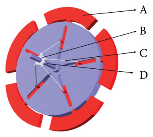
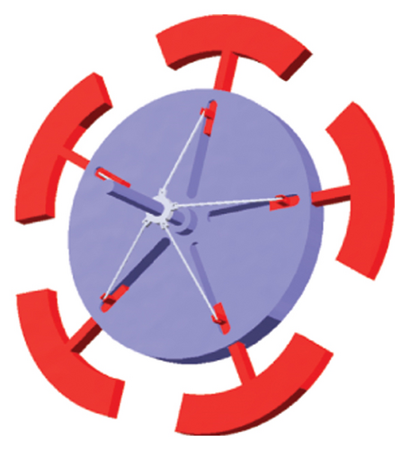
A pneumatic cylinder is one of the semiactive mechanisms that can be used to adjust the disk radius by moving ring B. Pneumatic cylinders use compressed air to move a piston within a cylinder, producing smooth, linear motion. By positioning and connecting the pneumatic actuator effectively to the mechanism, it allows precise control of the position of ring B, which in turn adjusts the disk radius, enabling continuous variation of the frequency. The pneumatic cylinder can be positioned alongside the central rod D or integrated into the frame of the mechanism, with its piston aligned to drive the movement of ring B. One end of the pneumatic cylinder is fixed to a stationary part of the structure, while the other end is connected to ring B through a linkage system. This setup ensures that as the piston moves, it directly influences the position of ring B along the rod D. The motion of the piston is controlled by the compressed air fed into the cylinder, allowing for precise adjustments of ring B and, consequently, the disk radius. This continuous movement of ring B causes the radial displacement of masses A, which changes the moment of inertia of the disk and, thus, the system’s frequency. A control system regulates the flow of compressed air into and out of the cylinder, allowing precise control over the direction and speed of the piston, ensuring smooth, nondisruptive adjustments to the disk radius. To ensure even more precise positioning, this pneumatic actuation not only offers flexibility in controlling the radius but also contributes to a more compact and efficient design compared to mechanical systems, such as gear-driven alternatives. As a semiactive mechanism, it enables real-time adjustments based on system requirements, ensuring optimal functionality and performance under varying conditions.
4. Parametric Study
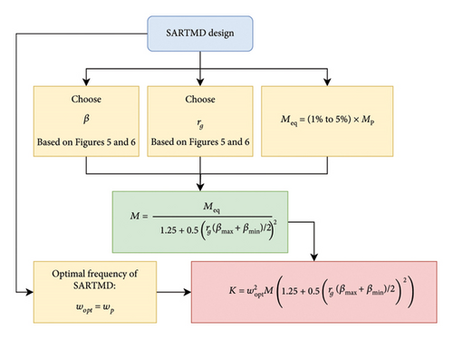
The proposed SARTMD has two key parameters that must be tuned: β(t) and rg. To achieve optimal performance, it is essential to conduct parametric studies to identify the most effective values for these parameters. In this context, we assume that the TMD has a mass of MTMD and the SARTMD has a mass of MSARTMD, with both systems having the same stiffness K. Given that both systems are tuned to the same frequency (ωSARTMD/ωTMD = 1), their mass ratio ϕ is defined in equation (18). This relationship shows that to achieve an optimal frequency, the SARTMD system requires a significantly lower mass compared to traditional TMDs.
Figure 5 illustrates how the mass ratio ϕ varies with different values of β for various rg values. As shown in the figure, increasing rg leads to a more significant reduction in mass, highlighting the potential of the SARTMD to achieve substantial mass savings. This reduction in mass is advantageous because it decreases the structural load and enhances the dynamic response, improving overall system performance.
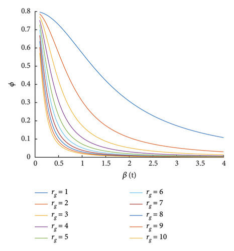
However, it is important to note that the impact of increasing rg diminishes once it surpasses a certain threshold. Specifically, for rg values between 6 and 10, the trend of mass reduction becomes nearly constant. Higher gear ratios increase the risk of gear backlash, particularly in dynamic systems operating at high frequencies. Backlash can reduce tuning accuracy, introduce delays in energy transfer, and potentially degrade vibration suppression effectiveness. Additionally, manufacturing tolerances become more critical as gear complexity increases, requiring high-precision fabrication and tighter assembly control to ensure concentricity and alignment. These challenges can lead to increased cost and complexity.
By plotting ωnd against different values of β and rg (Figure 6), it is observed that for β ≥ 1, the rate of frequency change (i.e., the slope of each curve) diminishes. This indicates that as β increases, the frequency variation becomes less sensitive to changes in β, which may be less effective for fine-tuning the system’s dynamic response. However, selecting a wide range for β results in impractical, abrupt changes in the radius, despite potential numerical improvements in the main structure’s responses. Such large variations could lead to sudden mechanical shifts that might compromise the stability or robustness of the system.
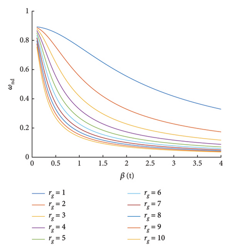
On the other hand, the slope of the frequency curve reaches its maximum for β ≤ 0.8, which suggests that smaller values of β enable faster and more responsive frequency changes. This rapid adjustment is particularly useful for tuning the system to a desired natural frequency quickly, without overshooting or underperforming. Smaller radius changes are also beneficial for maintaining smoother transitions and reducing mechanical stress on the components of the system, which in turn enhances reliability and lifespan.
Therefore, based on these observations, it is recommended to select rg within the range of 2 to 5, as this provides a balanced trade-off between performance and practicality. For β, a more limited range of 0.2 to 0.8 is advisable. This ensures that the system remains responsive to changes in frequency while avoiding excessive mechanical complexity or large, impractical variations in the radius ratio. By restricting β to this interval, it is possible to achieve a balance between efficient performance tuning and maintaining the structural integrity and operational stability of the SARTMD.
Once the optimal values for the parameters have been selected, the design of the SARTMD can proceed according to the flowchart presented in Figure 7.
5. Structural Model
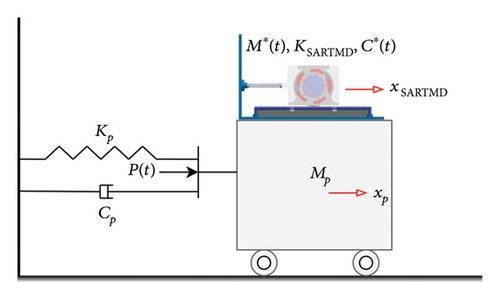
This study assumes linear behavior and small displacements for the SARTMD system. This simplification is frequently adopted in preliminary vibration control design and evaluation stages to facilitate analytical tractability, parameter sensitivity analyses, and straightforward control implementations without introducing the complexities of nonlinear dynamics. However, under pronounced nonlinear conditions, such as strong seismic events, amplitude-dependent frequency shifts and nonlinear mode interactions may lead to mistuning and reduced accuracy in the frequency-tracking algorithm, thereby diminishing the SARTMD’s effectiveness. Future studies should incorporate nonlinearities into the analytical framework.
6. Numerical Study and Results
| Primary system | TMD | SARTMD | Excitation | ||||
|---|---|---|---|---|---|---|---|
| Param. | Value | Param. | Value | Param. | Value | Param. | Value |
| M | 100 kg | M | 5 kg | M | 1.54 kg | mt | 0.1 kg |
| fn | 25 Hz | fn | 25 Hz | fn | 19.82–32.11 Hz | rt | 0.2 m |
| K | 2467.42 kN/m | K | 123.37 kN/m | K | 123.37 kN/m | αt | 12.5 Hz |
| C | 500 N.s/m | C | 7.85 N.s/m | C | 2.65–4.82 N.s/m | ωmax | 2π × 25 Hz |
| ζ | 5% | ζ | 0.5% | ζ | 0.5% | tacc | 2 s |
| μ | 5% | μ | 1.54% | ||||
| rg | 4 | ||||||
| β | 0.3–0.7 | ||||||
| 0.1 | |||||||
| M∗ | 3.03–7.95 kg | ||||||
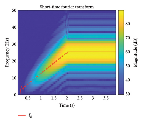
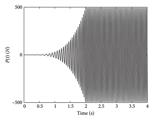
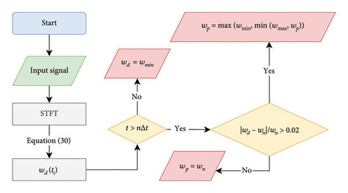
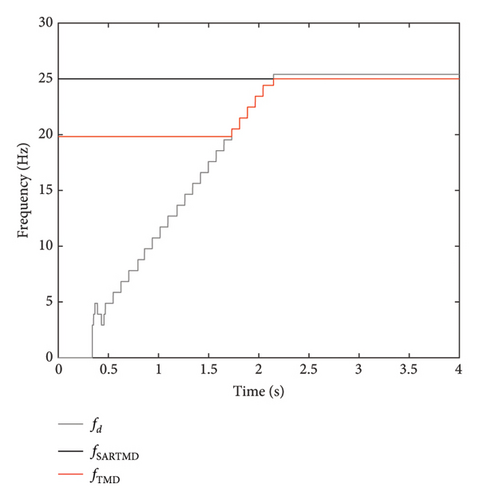
The primary system, TMD, and the proposed SARTMD are modeled and simulated in MATLAB’s Simulink environment under three different scenarios: (1) the uncontrolled primary system, (2) the primary system controlled using a TMD, and (3) the primary system controlled with the proposed SARTMD. The parameters for the primary system, TMD, and SARTMD are summarized in Table 2. For simulation purposes, the primary system’s natural frequency is assumed to be 25 Hz to reflect high-frequency vibration systems found in precision applications. However, this high frequency can cause gear backlash due to rapid oscillations when using SARTMDs. Despite these challenges, the 25 Hz frequency is used to evaluate the system’s performance under demanding conditions and compare the SARTMD’s effectiveness with a conventional TMD. While Den Hartog’s method recommends a different damping ratio, both the TMD and SARTMD are assumed to have an equal damping ratio of 0.5% to simplify the comparison.
| Control system | System | |x| (cm) | (cm/s) | (cm/s2) | |||
|---|---|---|---|---|---|---|---|
| Max | RMS | Max | RMS | Max | RMS | ||
| Uncontrolled | Primary | 0.199 | 0.098 | 31.186 | 15.419 | 4937.375 | 2437.001 |
| TMD | Primary | 0.084 | 0.016 | 12.109 | 2.277 | 1784.425 | 328.723 |
| Absorber | 0.064 | 0.216 | 96.401 | 33.391 | 14647.496 | 5182.748 | |
| SARTMD | Primary | 0.047 | 0.009 | 7.048 | 1.246 | 1092.828 | 194.315 |
| Absorber | 0.466 | 0.203 | 73.393 | 31.710 | 11603.552 | 4959.005 | |
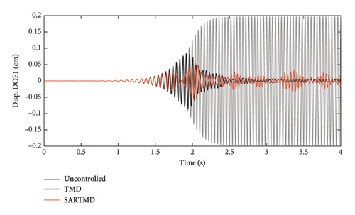
The time histories of displacement, velocity, and acceleration for both degrees of freedom and both the primary structure and the mass damper are depicted in Figures 12, 13, and 14. These figures encompass the responses of the uncontrolled structure, the structure controlled with a TMD, and the structure controlled using the SARTMD under excitation resembling rotating machinery. The selection of the excitation is designed to reach resonance after a few seconds, aligning its frequency with the natural frequency of the main structure. As anticipated, the presence of dampers contributes to a general reduction in vibrations and effectively prevents the onset of the resonance phenomenon. As shown in these figures, the performance of the SARTMD surpasses that of the TMD not only in minimizing the maximum responses but also in mitigating the responses throughout the entire excitation period. For a comprehensive understanding of SARTMD’s effectiveness, Figure 15 illustrates the response squares of displacement, velocity, and acceleration. This figure serves as a suitable metric for examining maximum responses, revealing that the SARTMD consistently outperforms the TMD, effectively controlling the structure’s responses more desirably throughout the entire excitation period.

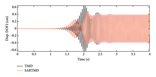
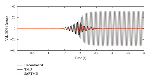
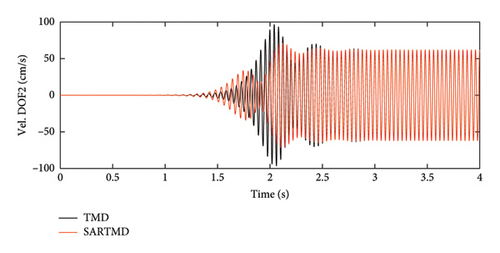
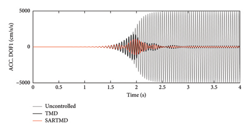
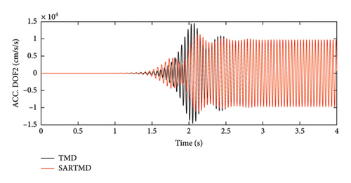
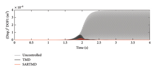
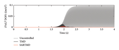
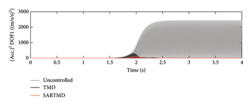
A distinctive feature of the SARTMD is its remarkable performance achieved with a mass that is only about 30% of the mass of the TMD. This characteristic underscores the novelty and efficiency of the proposed device. Despite its much lower mass, the SARTMD outperforms the TMD in reducing vibrations and effectively prevents resonance throughout the excitation period. This emphasizes the effectiveness and efficiency of the SARTMD as a lightweight and highly responsive control device for structural vibrations.
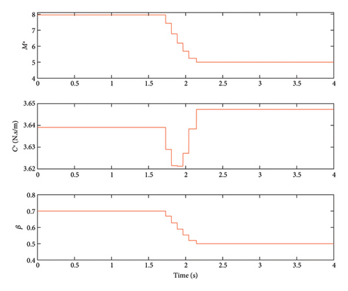
PIs presented in Table 4 confirm the points discussed earlier. The closer PIs are to unity, the better the system performance. As observed, the SARTMD has managed to reduce the maximum and RMS displacement of the primary system by 66% and 58% more than the TMD. The maximum velocity and acceleration of the primary system are reduced by 56% and 43%, respectively, and the RMS velocity and acceleration are reduced by 45% and 27%, respectively, compared to the structure controlled via a TMD. A common operational challenge faced by classical TMDs is the considerable spatial requirement for displacement. Another advantageous aspect of incorporating the SARTMD lies in the diminished displacement responses of the absorber mass compared to traditional TMDs. In the SARTMD, not only are the dimensions reduced due to its lower mass, but it also demonstrates a notable advantage over traditional TMDs with its maximum displacement being approximately 20% lower than that of the conventional TMD. This feature not only enhances the efficiency of space utilization but also underscores the practical advantages of the SARTMD in applications where spatial constraints are a critical consideration. Figure 16 illustrates the time history of the radius ratio (β), effective mass, and effective damping changes. This figure shows that the radius of the second disk in the SARTMD undergoes continuous alterations without any sudden jumps, meeting the constraints inherent in practical applications.
| Control system | PId,max | PIv,max | PIa,max | PId,rms | PIv,rms | PIa,rms |
|---|---|---|---|---|---|---|
| TMD | 0.423 | 0.388 | 0.361 | 0.165 | 0.148 | 0.135 |
| SARTMD | 0.238 | 0.226 | 0.221 | 0.087 | 0.081 | 0.080 |
7. Robustness of the SARTMD in the Presence of Off-Tuning
The robustness of the SARTMD is a key advantage that sets it apart from traditional passive damping systems. While off-tuning in the excitation frequency affects its optimal performance, the SARTMD remains highly effective in reducing vibrations, demonstrating strong resilience against frequency variations. Unlike a conventional TMD, which experiences significant performance degradation when detuned, the SARTMD maintains its functionality even when the excitation frequency deviates from the ideal tuning condition. This robustness is crucial in real-world applications where external excitations, such as wind, seismic activity, or ocean waves, rarely remain at a fixed frequency.
To study this, we introduced different levels of noise to the tuning frequency of the SARTMD and analyzed its performance under varying excitation conditions. The PIs and response values, as shown in Tables 5 and 6, and Figures 17 and 18, reinforce this robustness. As the off-tuning level increases from 10% to 30%, there is only a gradual increase in PIs, indicating that the system does not experience a sharp decline in damping efficiency. For instance, the peak displacement performance index, PId,max, increases only slightly from 0.268 to 0.284, while the RMS acceleration index, PIa,rms, increases from 0.086 to 0.113. These variations are relatively small, highlighting the system’s ability to sustain effective vibration mitigation even under detuned conditions. Similarly, in terms of direct response values, the primary structure’s displacement and acceleration remain well-controlled despite increasing detuning, with only minor increases in peak and RMS values.
| Off-tune (%) | PId,max | PIv,max | PIa,max | PId,rms | PIv,rms | PIa,rms |
|---|---|---|---|---|---|---|
| 10 | 0.268 | 0.253 | 0.248 | 0.097 | 0.089 | 0.086 |
| 20 | 0.277 | 0.267 | 0.261 | 0.109 | 0.101 | 0.097 |
| 30 | 0.284 | 0.270 | 0.266 | 0.125 | 0.116 | 0.113 |
| Off-tune (%) | System | |x| (cm) | (cm/s) | (cm/s2) | |||
|---|---|---|---|---|---|---|---|
| Max | RMS | Max | RMS | Max | RMS | ||
| 10 | Primary | 0.053 | 0.010 | 7.883 | 1.374 | 1223.089 | 210.636 |
| Absorber | 0.515 | 0.208 | 78.618 | 32.351 | 14105.456 | 5081.286 | |
| 15 | Primary | 0.055 | 0.011 | 8.334 | 1.551 | 1289.309 | 237.197 |
| Absorber | 0.526 | 0.211 | 79.613 | 32.821 | 15209.612 | 5190.007 | |
| 20 | Primary | 0.056 | 0.012 | 8.419 | 1.790 | 1311.699 | 274.251 |
| Absorber | 0.518 | 0.215 | 79.793 | 33.445 | 16370.866 | 5338.214 | |
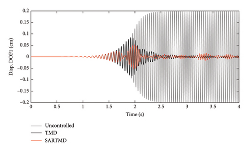
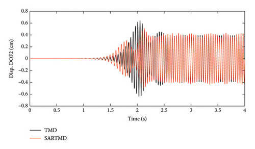
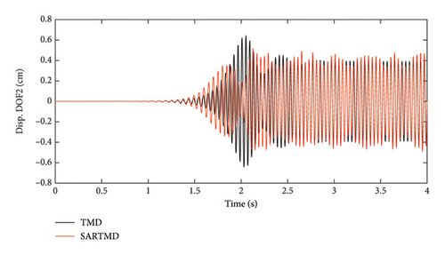
This robustness stems from the semiactive nature of the SARTMD, which allows for adaptive control strategies that adjust damping properties in real time, unlike passive TMDs that rely on fixed tuning. Even when faced with uncertainties in the excitation frequency, the SARTMD continues to provide substantial vibration reduction, ensuring improved structural stability and safety. The absorber experiences greater motion and acceleration as off-tuning increases, but this is expected since it plays the role of energy dissipation. More importantly, the primary structure remains within safe operational limits, confirming that the SARTMD effectively protects it from excessive vibrations even under detuned conditions.
8. Conclusion and Summary
A novel SARTMD is proposed and investigated in this study, offering significant advancements over classical TMDs by incorporating both translational and rotational motions. The system transfers the rotational motion of the damper’s main mass to additional disks via a planetary gearbox, while a simple umbrella-like mechanism adjusts the radius of the secondary mass. This radius alteration changes the moment of inertia, enabling the system frequency to adapt dynamically within a specified range. A control algorithm is employed to instantaneously identify and fine-tune the SARTMD’s frequency to match the dominant excitation frequency, effectively mitigating structural responses.
The performance of the SARTMD is governed by two key parameters: the radius ratio and the gearbox ratio. Parametric studies are conducted to provide practical recommendations for selecting these parameters to optimize performance. One critical design consideration is ensuring pure rotation of the cylindrical mass by preventing slippage. A practical solution proposed is placing a rack mechanism beneath the cylindrical mass to maintain its pure rolling motion.
Adding rotational motion significantly reduces the required mass ratio of the damper to the structure, enhancing its efficiency and practical applicability. Numerical studies demonstrated that the SARTMD achieves this reduction with a 70% smaller mass compared to a conventional TMD, while delivering superior vibration control.
Using MATLAB and Simulink for numerical modeling, the SARTMD was tested on a structure subjected to rotating machinery excitation. Results showed remarkable performance improvements over an uncontrolled structure, with reductions of 76.24%, 77.40%, and 77.87% in maximum displacement, velocity, and acceleration, respectively. Additionally, the RMS values for displacement, velocity, and acceleration were reduced by 91.29%, 91.92%, and 92.03%, respectively. Also, while off-tuning slightly affects peak performance, it does not significantly compromise the effectiveness of the SARTMD.
Furthermore, under gradual frequency changes, the radius ratio of the SARTMD adjusts smoothly without abrupt jumps, ensuring a continuous and effective mass variation. These results highlight the SARTMD’s ability to achieve significant response reductions with a considerably lower mass ratio, positioning it as a highly efficient and practical alternative to conventional TMDs.
Conflicts of Interest
The authors declare no conflicts of interest.
Funding
The authors received no financial support for the research, authorship, and/or publication of this article.
Open Research
Data Availability Statement
No data were utilized in this study. The code developed by the authors is available upon request.


