Turbulent Airflow and Thermal Analysis in a Circular Tube Heat Exchanger Fitted With Turbulence-Inducing Vortex Generators (X-V Baffles)
Abstract
The research presents an investigation into airflow configuration, thermal behavior, and convective heat transfer enhancement in a circular heat exchanger tube fitted with turbulence generators. These turbulence generators, referred to in this study as X-V baffles (XVBs), were developed to generate swirling flow within the heat exchanger tube, which is directly related to the enhancement of heat transfer rates and the overall performance of the heat exchanger. Additionally, the XVBs were designed with consideration for practical application and ease of maintenance in real-world industrial settings. The study examines the variables influencing airflow topology and thermal structure, including the blockage ratio (g/D = 0.05–0.20), pitch ratio (P/D = 1–2), flow direction (FD-VD and FD-VU), and types of turbulence generators (Type S and Type T XVBs). The research was conducted within the turbulent flow regime, with Reynolds numbers ranging from 3000 to 12,000 (Re = 3000–12000). The results are presented in terms of observed flow behavior within the test tube, such as cross-flow streamlines, streamwise flow streamlines, Nusselt number distribution, and fluid temperature distribution. The findings clearly show the formation of swirling flow in the heat exchanger tube when XVBs are installed. An increase in the blockage ratio and a decrease in the pitch ratio lead to a more intense swirling flow. The intensity of this swirling flow is directly correlated with the degree of disturbance in the thermal boundary layer (TH-BL). The maximum enhancements in Nusselt number and friction factor due to XVB installation are 7.24 and 58.01 times greater, respectively, compared to a smooth tube without XVBs. The maximum thermal enhancement factor (TEF) achieved is 2.27, obtained from the case with the Type T XVB at a blockage ratio of g/D = 0.05, a pitch ratio of P/D = 1, and a flow direction in the FD-VD configuration.
1. Introduction
Heat is a form of energy that is essential in daily life and various industrial systems. When discussing thermal energy, an important device related to this concept is the heat exchanger. A heat exchanger is an engineering device designed to exchange heat between two fluids through a surface known as the heat transfer surface. Heat exchangers play a crucial role in many industries and can be classified into several types, including shell-and-tube heat exchangers, plate-fin heat exchangers, fin-and-tube heat exchangers, and double-pipe heat exchangers. The choice of heat exchanger type depends on factors such as the desired heat transfer rate, compatibility with the fluids used, available installation space, and the specific industry requirements. Given the significance of heat exchangers, there is considerable interest among operators and organizations in developing high-performance models to enhance thermal efficiency. Such advancements can help meet the growing energy demands of the world while promoting the conservation and efficient use of energy.
Currently, the development of heat exchangers can be achieved through various methods. One effective approach is adding vibrations to the heat exchange system, which can enhance the convective heat transfer coefficient and positively impact the mixing quality of fluids within the system. Another popular method involves inducing vortex flow to disrupt the thermal boundary layer (TH-BL) by installing small devices that obstruct the fluid flow. This obstruction creates a pressure difference between the front and back of the device, leading to vortex flow within the heat exchanger. These small devices are known as vortex generators or turbulence generators. The use of vortex generators has gained popularity for improving heat transfer performance in heat exchangers, as this method does not incur additional energy costs. Furthermore, it effectively increases the heat transfer rate. Vortex generators can be categorized into several types, including wings, winglets, ribs, baffles, grooves, and conical rings. The choice of vortex generator depends on its suitability for the specific characteristics of the heat exchanger and the fluids involved in the process. This research focuses on enhancing the thermal performance and studying the aerodynamic behavior of heat exchangers by installing vortex generators.
Many studies emphasize the enhancement of thermal performance in heat exchangers using vortex generators. Researchers have employed both experimental setups and numerical simulations, each with its advantages and disadvantages. The strength of experimental studies lies in the realism of the results; however, this method requires various specialized techniques to elucidate the airflow structure and thermal behavior within the heat exchanger, which can be costly. In contrast, numerical methods excel in providing detailed insights into the behavior occurring in heat exchangers. Nevertheless, this approach necessitates model validation to ensure the accuracy and reliability of the results obtained. Examples of research related to enhancing the performance of heat exchangers using vortex generators are presented below.
Among the earliest and most widely studied vortex generators, twisted tapes [1–4] in various configurations have garnered significant attention. Obaidi [5] studied a novel twisted tape designed to improve thermohydraulic performance in a pipe using CFD and DoE analysis methods. Various twisted configurations were employed, including twisted width, thickness of the twist, number of turns, and thickness of the inward twist. Their investigation revealed that the enhanced heat transfer rate was approximately 42.72%. Crespo-Quintanilla et al. [6] investigated the use of twisted tubes and twisted tapes as tools for enhancing convective heat transfer in both novel designs and retrofitting of shell-and-tube heat exchangers. They found that the surfaces offering the best trade-off between heat transfer enhancement and friction loss were simple twisted tubes and twisted tubes with triple-channel twisted tape, achieving performance enhancement coefficients (PECs) of 3.06 and 2.59, respectively. Alsharifi et al. [7] presented an optimal design and thermal performance assessment of a photovoltaic/thermal collector using porous twisted tape inserts as the enhancement technique. They found that increasing the tube diameter from 8 to 12 mm led to an improvement in electrical and thermal energy efficiency by 3.51% and 31.58%, respectively. Conversely, increasing the twisted tape porosity from 0.8 to 0.96 resulted in a 41.61% reduction in thermal energy efficiency and a 7.18% decrease in electrical energy efficiency. Mehta et al. [8] examined the effects of single and dual twisted tapes in parabolic trough solar collectors for Reynolds numbers (Re) ranging from 1000 to 9000. According to their findings, the two twisted tape configurations that showed the greatest improvements in performance were the single twisted tape insert with a pitch-to-width ratio of 1 and the dual twisted tape insert with a pitch ratio of 2. Compared to the reference case, the dual twisted tape arrangement resulted in a 14% increase in thermal efficiency, along with enhancements of 372% and 1600% in the Nusselt number (Nu) and friction factor, respectively. The effects of ultrasonic treatment on the thermohydraulic characteristics of shell-and-tube heat exchangers with twisted tape were investigated by Wang et al. [9]. From their investigation, the maximum increase in the Nu was 36.53%, the maximum reduction in the friction factor was 12.50%, and the maximum value of the performance enhancement criterion was 1.41. Göksu [10] reported on the energy and exergy analysis of various designs of twisted tapes in PV/T systems. The effects of different pitch ratios, widths, and thicknesses on the performance of PV/T systems were examined across Re ranging from 500 to 1900. The highest performance evaluation criterion value of 1.535 was achieved with a width of 9.5 mm, a pitch ratio of 3, a thickness of 0.5 mm, and a Re of 500. Liaw et al. [11] numerically investigated the enhancement of supercritical carbon dioxide heat transfer in helical tube heat exchangers with twisted tape inserts. They came to the conclusion that due to the increased secondary fluid flow inside the helical tested tube, the addition of twisted tape inserts augmented the performance of heat exchange. They observed that increasing the number of turns and the width of the tape did not necessarily result in greater heat transfer enhancement. Using supercritical CO2 as their working fluid, Oketola and Mwesigye [12] conducted a computational study of the overall thermal and thermodynamic efficiency of a high concentration ratio parabolic within solar collector with a unique vortex generator (modified twisted tape). They concluded that using the redesigned twisted tape inserts reduced receiver heat losses and circumferential temperature gradients, enhanced thermal efficiency by 6%, and improved heat transfer performance by up to 73%. For Re between 6000 and 14,000, Chaurasiya et al. [13] reported on the improvement of convective heat transfer coefficient and the friction loss in a dimpled structure twisted tape with a double-pipe heat exchanger utilizing SiO2 nanofluid. According to their findings, a secondary vortex flow was created when a V-cut was added to the tape. At a Re of 6000, the heat transfer rate improved by 87.73%, but the friction factor climbed 6.37 times that of a smooth pipe. Xiao et al. [14] studied the effects of an assembled self-rotating twisted tape in double-pipe heat exchangers on thermal structure and flow resistance. They concluded that the Nu of the assembled self-rotating twisted tape increased by 22.67%, while the friction factor decreased by 26.25% compared to that of the stationary twisted tape. Using numerical simulations, Sedaghat et al. [15] examined heat transport in a heat exchanger using basic, perforated twisted tapes for Re between 200 and 1000. Their results showed that, compared to the simple twisted tape, the perforated twisted tapes achieved an increase in the Nu of 15.24%, a decrease in the friction factor of 22.26%, and a growth in the coefficient of thermal performance of 18.07%. Laminar and turbulent fluid flow in a coiled flow reverser with a twisted tape insert as its turbulators was studied numerically and experimentally by Farhadi et al. [16]. They asserted that a twisted tape with a twist ratio of 15.73 and no holes performed best in the laminar flow regime at a Re of 2000. The same twisted tape also showed optimal performance in the turbulent flow regime at a Re of 17,000. Additionally, they found that the maximum thermal performance ratio was 1.55 in the laminar regime, compared to 0.99 in the turbulent regime. In an engine heat exchanger system, Luo et al. [17] demonstrated the thermal-frictional characteristic of a novel specific pattern twisted tape and helical coiled wire generators. According to their research, the new geometry provided significant advantages over a simple twisted tape construction. A pitch ratio of 2 mm produced the greatest convective heat transfer coefficient, improving the tube by 125% over a plain tube. They concluded that the presence of these turbulators resulted in a 960% increase in pressure drop and a 142% increase in the heat transfer coefficient. As a result, the thermal performance improved by 20% to 1.31 when compared to a simple twisted tape turbulator.
The hydrothermal and energy-saving capabilities of a tested section (minichannel heat sink) with various wire coil insert vortex producers that created swirling flow were documented by Feng et al. [18]. The findings demonstrated that the square wire coil insert produced the greatest overall thermal performance and heat transmission. The overall thermal performance increased initially and then decreased when the pitch was raised. The square coil insert demonstrated significant potential to enhance the overall performance of the minichannel heat exchanger at higher Re. Wang et al. [19] studied thermal performance enhancement in a double tube heat exchanger using a combination of bubble injection and helical coiled wire inserts. According to their experimental results, the addition of bubble injection, the use of the helical coiled wire generator, and the combination of two techniques led to increases in heat transmission of 66%, 78%, and 156%, respectively. They could have achieved a maximum value of 1.28 for their thermal enhancement factor (TEF). Using both new magnetic turbulators and helical coil wire turbulators at the same time improved the heat exchanger’s thermal performance were reported by Yao et al. [20]. Heat transfer increased by 237%, 262%, and 491%, respectively, when the helical coil wire turbulator, magnetic turbulator, and both turbulators were used together. A TEF of 3.78 was the optimal value. Refrigerant condensation heat transfer and pressure loss in horizontal tubes with full and partial coiled wire inserts were experimentally investigated by Rajabi et al. [21]. According to their experimental findings, the heat transfer coefficient was enhanced by 95%, 40%, and 18%, respectively, when coiled wire inserts of 1000 mm (full-length), 200 mm, and 100 mm were used instead of the reference case (smooth tube). Celik et al. [22] presented the performance optimization of a heat exchanger with a coiled-wire turbulator insert using various machine learning methods. The influences of Re, wire thickness, pitch, and coiled-wire length on thermal performance were considered. Feng et al. [23] used rectangular wire coils and twisted tapes to enhance the heat transfer rate in square minichannels for Re ranging from 520 to 1145. They noted that the swirl flow generated by the rectangular coil interacts with the swirl flow from the twisted tape, promoting fluid disturbance and flow mixing. They concluded that the best overall thermal performance values for the combined full-length wire coil with full-length twisted tape and the full-length wire coil alone were in the ranges of 1.70–1.94 and 1.57–2.13, respectively. Helically coiled wire-induced swirling flow within a round tube at controlled velocities was investigated by Hata and Shibahara [24]. A novel methodological strategy for choosing wire-coil inserts in thermal equipment was provided by García et al. [25]. They found that the wire coil’s essential Re needs to be lower than the equipment’s operating Re range in order to improve heat transmission. They also reported that the greatest temperature reduction, approximately 6°C (around 15%), occurred within the Re range of 700–2000. In addition to studying the impacts of three generators types (wire coil, twisted tape, and perforated twisted tape), Balaga et al. [26] examined the augmentation of heat transmission of functionalized multiwalled carbon nanotubes. They observed that the improvements in friction factor and heat transfer were 1.14 times and 21.66%–31.66%, respectively. The combined effects of twisted tape and perforated twisted tape, along with the wire insert at a twist ratio and coil pitch of 3, resulted in improvements in convective heat transfer and friction loss characteristic of 32.31%–94.03% and 43.94%–141.07%, respectively, when compared to a smooth tube with 0.03 weight percent hybrid nanofluid. The corresponding friction factor increases were 1.09 and 1.13 times. Keklikcioglu and Ozceyhan [27] used a mixture of ethylene glycol and water as the working fluid to increase the transfer of heat in a tube with conical wire coils. At the lowest Re (Re = 4627), they found that a divergent wire coil insert with a pitch-to-diameter ratio of 2 produced the highest performance assessment criterion of 1.62. The impact of a new serrated wire coil insert on the airflow and thermal characteristics of a tubular heat exchanger was examined by Chompookham et al. [28]. According to their research, as compared to smooth tubes, the insertion of the coils raised the friction factor (f) and Nu by roughly 3.31–8.16 times and 1.75–2.46 times, respectively. 1.41 was the highest thermal performance improve factor. The fluid dynamic and condensation heat transfer attributes of two-phase NaCl-H2O fluids on the exterior surface of a sweeping spiral coil in a hydrothermal vent were investigated numerically by Ren et al. [29]. The “normal region” and the “island region,” where convection heat transfer and condensation are the primary heat transfer mechanisms, are the two separate heat transfer regions they found. Both the spoiler effect from the spiral construction and vapor condensation were responsible for the creation of the “island region.” Furthermore, in the “island region,” heat flux rose as salinity decreased, whereas in the “normal region,” there was only a minor correlation between heat flux and salinity. The improvement of thermal-hydraulic efficiency in helical coil heat exchangers with twisted tube configurations was examined numerically by Ghazanfari et al. [30]. They investigated at how heat transfer efficiency and pressure drop were affected by Re (Re = 10, 000–100,000), pitch spacing or pitch length (11, 7.2, 5.5, and 3.6 mm), and twisted tube arrangement (cocurrent and counter-current). Higher Re boosted heat transfer by around 35% and decreased the resistance factor by about 25%, according to the data. Wang et al. [31] used a novel conical braided wire turbulator to increase the engine heat exchanger’s heat transfer efficiency. They observed that the Nu was 2.84 times higher than that of a typical tube, with an optimum TEF of 1.4. Wang et al. [32] investigated the shell-side thermal–hydraulic efficiency of a helically coiled tube heat exchanger system for deep underground spaces. They found that increasing the coil diameter from 30 to 40 mm and the coil pitch from 7.5 to 9.0 mm led to increases in the Nu by 16.5% and 6.7%, respectively, as well as increases in the friction loss by 575.2% and 147.1%. However, the performance evaluation criterion decreased by 38.4% and 21.1% at an air velocity of 5 m/s. Sharaf et al. [33] illustrated the influences of multispring wire configurations on the hydrothermal efficiency of a double tube heat exchanger for Re ranging from 4500 to 7500. They reported that the three-wire configuration demonstrated a 112% enhancement in the Nu compared to plain tubes, along with a maximum friction factor enhancement of 134%. Additionally, they noted that the exergy efficiency significantly improved, increasing by 61% with the three-wire setup compared to plain tubes. Yuan et al. [34] experimentally and numerically investigated a novel double shell-pass multilayer helically coiled tube heat exchanger. Their results revealed that the heat transfer rate and thermal effectiveness of this heat exchanger were enhanced by 5.1% to 12.9%. They also concluded that the overall heat transfer coefficient improved by 21.5% to 29.0%, while the shell-side heat transfer coefficient increased by 36.2% to 47.5%. Beyond the twisted tapes and wire coils previously introduced, other types of vortex generators—such as V-ribs/baffles [35], inclined baffle [36], V-orifice [37] and wings/winglets [35, 38–43]—have also gained significant interest and have been the subject of continuous investigation.
Typically, studies on enhancing thermal performance in round heat exchanger tubes through the installation of vortex generators mainly focus on twisted tape and wire coil types. The advantages of these two vortex generator types include ease of installation in round tubes. Other types, such as winglets, baffles, and ribs, have been less commonly developed for round tubes due to the challenges of installation on curved surfaces. However, these vortex generators can be quite effective in increasing heat transfer. Additionally, installation on curved surfaces often results in small gaps between the heat exchanger tube surface and the vortex generators, which can have both positive and negative effects on heat transfer.
Based on a comprehensive review of previous studies, the research team focused on baffle-type vortex generators—particularly V-shaped baffles—which have demonstrated high effectiveness in enhancing heat transfer performance. The V-shaped structure was adopted as the foundational design for the vortex generator and was further developed for application in circular heat exchanger tubes. This focus is especially relevant, as circular heat exchangers are widely employed across various industrial sectors and thermal systems. However, integrating vortex generators into circular tubes presents significant challenges due to the curved geometry of the internal surface. In this context, the present study also considers other critical factors such as ease of installation, maintenance, and manufacturability, which are essential for practical implementation. To gain a detailed understanding of the flow behavior and thermal characteristics induced by the vortex generators, a numerical modeling approach was employed. This approach provides valuable insight into the performance of vortex generators in curved channels and contributes to the future development of high-efficiency heat exchangers for real-world industrial applications.
2. Numerical Model Description
Figure 1 shows the heat exchanger tube with both types of XVB installed. The test was conducted using a circular heat exchanger tube with a diameter (D) of 0.05 m. The turbulence generators were installed within the circular tested tube to create swirling flow. The X-V baffle (XVB) is the name given to the swirling flow generator. The name XVB originates from the unique X-V-shaped design of the swirling flow generator. When viewed in the y-z plane (transverse plane), the baffle appears as an “X,” and when saw in the x-z plane (streamwise plane), it resembles a “V.” In this context, “g” represents the thickness of the XVB plate. From previous studies [44] conducted by our research team, it was found that XVB provides relatively high heat transfer rates and efficiency during laminar flow conditions. However, studies on turbulent flow conditions have not been presented. The g/D ratio for this research ranges from 0.05 to 0.20. The distance between the XVBs (pitch spacing/pitch length) is denoted by “P,” with the pitch to diameter ratio or P/D ratio set at 1, 1.5, and 2. As reported in [44], the chosen pitch range was previously identified as optimal for achieving the highest heat transfer enhancement. Flow tests were conducted in two flow directions (FDs). When viewed in the x-z plane, the end of the V pointing in the direction of the flow (+x) is referred to as flow direction: V-downstream (FD-VD), while the end of the V pointing against the flow (-x) is called flow direction: V-upstream (FD-VU). The length of the periodic module is denoted by “L.” The L/D values are set at 1, 1.5, and 2 for the cases, where P/D equals 1, 1.5, and 2, respectively. The categories of XVB are categorized into two formats, referred to as Type S and Type T. Both types of XVB differ in the area of the joint of the central plate. Previous research has found that even minor differences in the joint can significantly affect the heat transfer rate and the performance enhancement of heat transfer. The flow regime studied is turbulent flow, characterized by Re ranging from 3000 to 12,000, as observed at the entrance of the heat exchanger tube. The model was developed using an irregular hexahedral mesh, featuring a fine grid near the heat exchange surface. For this study, an enhanced wall treatment function was selected, and the y+ value was verified to be approximately 1.
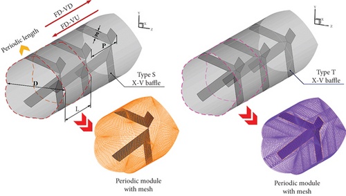
The developed model applies periodic boundary conditions for both flow and heat transfer at the inlet and outlet. These conditions simulate pipes where the inlet length is more than 10 times the diameter, as found in industrial heat exchanger systems. Flow and heat transfer occur in the fully developed region, with a constant heat flux of 600 W/m2 applied to the heat exchanger wall. The XVB is thermally insulated.
3. Mathematical Foundation, Assumption, and Initial and Boundary Conditions
- •
The tested tube’s flow and thermal configuration are thought to be three-dimensional (3D) (3D heat and fluid flow) and constant.
- •
The flow is considered incompressible, and the flow regime is turbulent. The Re is evaluated based on the conditions at the inlet of the test tube.
- •
The working fluid used in the round tested tube is air. The temperature variation of the air during the test does not exceed 20 K/°C. Therefore, the thermal properties of the fluid change very little and can be considered constant throughout the test.
- •
Body forces and viscous dissipation are not considered in this study.
- •
The effects of conduction, natural convection, and thermal radiation are negligible and therefore not considered in this heat transfer study; only forced convection inside the heat exchanger tube is analyzed.
Based on the details of the study presented above, the equations related to this research are as follows [35]:
4. Validation of the Numerical Domain
Validating the accuracy of numerical models is a crucial step in studies using numerical methods, as it helps confirm the correctness and precision of the research consequences. The validation of the model can be separated into three steps: (1) validation of the appropriate grid size, (2) validation of the smooth wall empty pipe, and (3) comparison of numerical results with previously published research. Testing across all three components ensures that the developed numerical model is sufficiently reliable for predicting flow pattern and heat transfer characteristics in heat exchangers with installed turbulence generators.
4.1. Validation of the Appropriate Grid Size (Grid Independence)
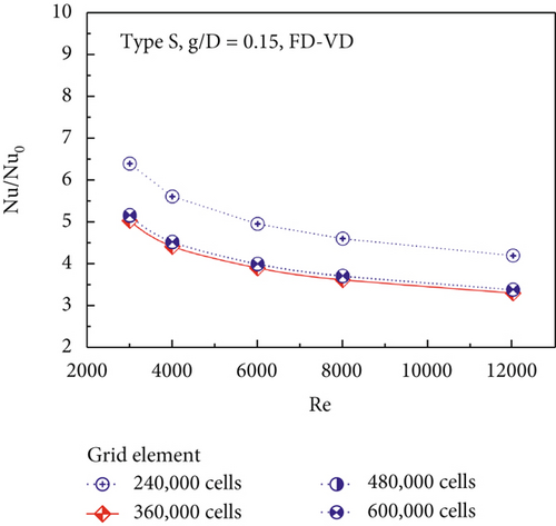
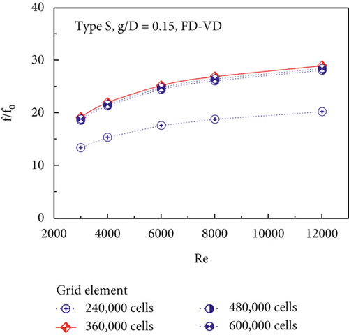
The verification of the appropriate grid number for the numerical model involves creating models with varying grid counts of 260,000, 360,000, 480,000, and 600,000. A comparison of both the Nu/Nu0 and f/f0 values for the XVB Type S case study, with g/D = 0.15 under the FD-VD, is presented in Figure 2a,b, respectively. The trends of Nu/Nu0 and f/f0 for all models are similar; specifically, Nu/Nu0 tends to decrease as the Re increases, while f/f0 increases with rising Re. The numerical models with grid counts of 360,000 to 600,000 exhibit clustering of Nu/Nu0 and f/f0 values, with differences ranging from 0.7% to 2%. In contrast, the model with a grid count of 240,000 shows significant discrepancies in Nu/Nu0 and f/f0 compared to the other models. Selecting an appropriate grid count is crucial for optimizing study duration and resource management; therefore, a grid count of 360,000 was chosen for all subsequent case studies.
4.2. Validation of the Smooth Wall Empty Pipe
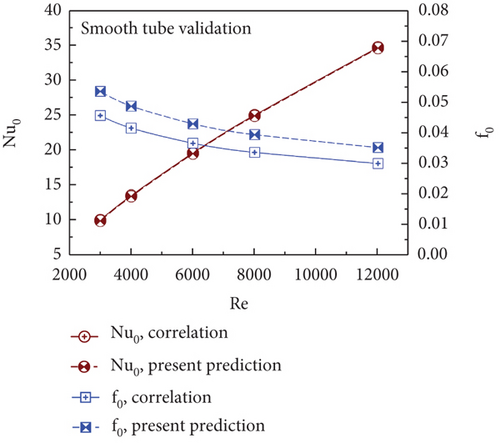
The validation of the empty pipe can be performed by comparing the values obtained from the current study with those derived from correlation equations [45] for Nu and f within the same study range. Figure 3 illustrates the comparison between the values obtained from the current study and those derived from correlation equations. The figure shows that the Nu value tends to increase as the Re increases, while the f value tends to decrease with rising Re. The trends for both Nu and f from the two sources align in the same direction. The Nu values from both data sources exhibit minimal differences, while the maximum difference in the f values is 17.25%, with an average difference of approximately 12%.
4.3. Comparison of Numerical Results With Previously Published Research
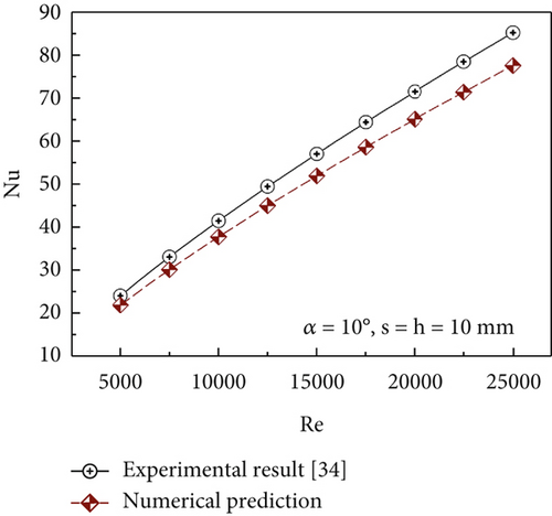
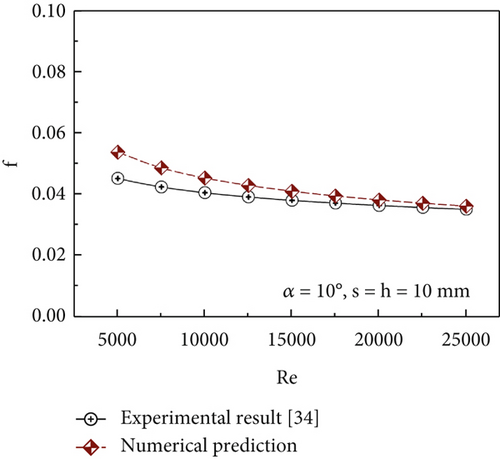
Another important verification step is to compare the results with a previously published study [46] regarding both the Nu and the friction factor (see Figure 4). The comparison shows that the Nu increases with the Re, while the friction factor (f) tends to decrease as Re increases. This trend is consistent in both the results obtained from the current study and those from previous research [46]. The average discrepancies in the Nu and friction factor data from the two sources are 9% and 8.97%, respectively.
Based on the results of the validation tests for the model, it can be summarized that the currently developed model is reliable for predicting air-flow behavior, heat transfer structure, and thermal performance in heat exchanger tubes with installed XVB. The results obtained from this study are expected to be accurate and realistic.
5. Numerical Result and Discussion
5.1. Flow and Heat Transfer Characteristics
The study outcomes are presented in the form of cross-flow streamlines, streamwise flow streamlines, temperature distribution in the cross-flow plane, and contour distribution of the Nu on the heat-transfer surface of the heat exchanger tube.
The flow streamlines in the cross-flow plane are illustrated in Figure 5. The streamlines are plotted at the cross-sectional planes of x/D = 1, 2.25, 3.5, 4.75, and 6. As observed, the installation of both types of XVBs significantly modifies the flow behavior compared to the smooth, unobstructed tube. The presence of the XVBs induces swirling flow by obstructing the main flow and creating a pressure difference between the upstream and downstream sides of the XVB plates. This pressure gradient is the primary mechanism responsible for generating the swirling motion. Swirling flow is observed in all investigated cases.
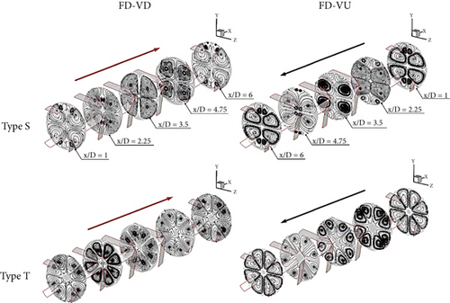
The flow structure generated by the Type S XVB consists of four primary swirling cores along with several smaller vortices located near the boundaries of the plane. In contrast, the Type T XVB produces eight primary swirling cores, all of which are approximately equal in size. Variations in the g/D ratio have a minimal impact on the location of the main swirling cores. Nevertheless, the overall swirling flow structure remains consistent across all XVB configurations and FDs, as shown in Figure 6. The positions of the swirling flow cores or vortex cores (VCs) are presented in Figure 7. For a given XVB type, altering the FD influences the rotational direction of the swirling motion in the y- z plane.
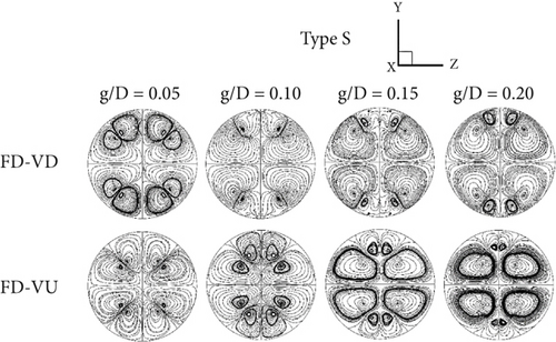
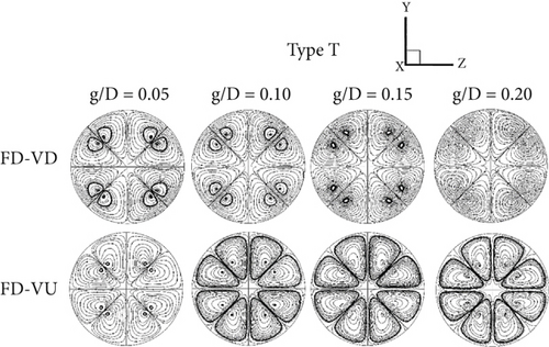
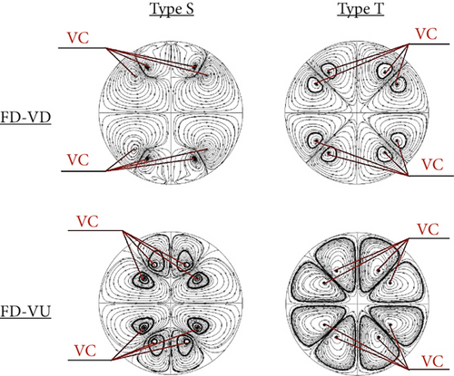
Figure 8 presents the streamlines within the heat exchanger tube equipped with XVBs. The figure illustrates that the installation of XVBs generates swirling flow throughout the tube. This visualization was produced using a method that highlights the swirling flow in contact with the tube surface, indicating that a portion of the swirling streamlines directly interacts with the inner wall of the heat exchanger tube. This interaction is expected to influence the TH-BL, a key factor governing the heat transfer rate. However, based solely on the streamline visualization, modifications to the TH-BL cannot be clearly identified. The assumption that such flow behavior alters the TH-BL is inferred rather than directly observed. To address this limitation, the temperature distribution in the cross-flow plane is presented, as it more clearly reveals changes in the TH-BL.

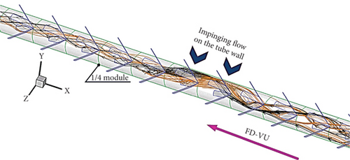
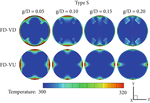
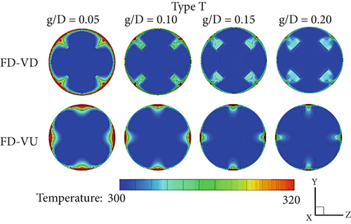
Figure 9 illustrates the temperature distribution of the fluid in the cross-flow plane at x/D = 1, 2.25, 3.5, 4.75, and 6 for both types of XVB and FD-VD and FD-VU. Higher-temperature regions are represented by red contours, whereas lower-temperature regions are indicated by blue contours. In the case of a smooth tube without XVB installation, blue contours typically appear in the center of the tube, while red contours are located near the boundaries of the cross-flow plane.
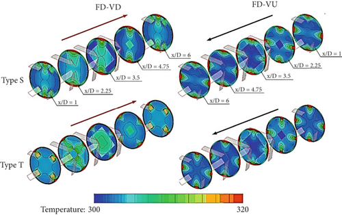
With the installation of the XVB, swirling flow is induced within the heat exchanger tube, resulting in the outward dispersion of blue contours from the center of the cross-flow plane and a noticeable thinning of the red contours. This behavior suggests an enhancement in the fluid mixing quality. The TH-BL is disrupted, as evidenced by the reduced thickness of the red contours near the boundaries of the cross-flow plane.
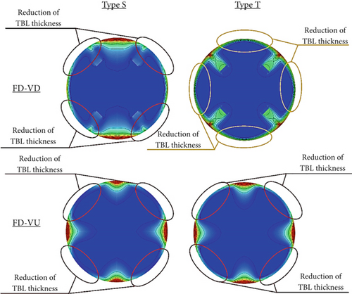
The installation of XVBs clearly induces disturbances in the TH-BL, resulting in a thinner TH-BL in all case studies. However, the thinning is not uniformly distributed along the boundaries of the cross-flow plane. A significantly reduced TH-BL thickness is observed where the swirling flow directly impinges on the inner surface of the heat exchanger tube. Meanwhile, regions where the swirling flow does not interact directly with the wall still contribute to enhanced fluid mixing. As the g/D ratio increases, a noticeable decrease in TH-BL thickness is observed for both XVB types and across all FDs (see Figure 10). This reduction is attributed to the intensified swirling flow induced by the higher g/D ratio, which causes greater disruption of the TH-BL.
The level of disturbance in the TH-BL is directly proportional to the increased heat transfer rate. The regions of disturbance within the TH-BL for each case study are shown in Figure 11. These disturbed areas are similar across all cases, with the exception of Type T XVB under the FD-VD. Areas where the flow stream significantly interacts with the surface, resulting in a reduction in the TH-BL, exhibit higher heat transfer rates compared to regions where the flow does not make direct contact with the surface (see Figure 12).
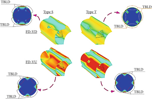
As previously discussed, the level of disturbance in the TH-BL is directly proportional to the increased intensity of the swirling flow as the flow obstruction ratio (g/D) increases. This results in the highest heat transfer rate at g/D = 0.20 and the lowest heat transfer rate at g/D = 0.05, for the same type of XVB, FD, and P/D ratio (see Figure 13).
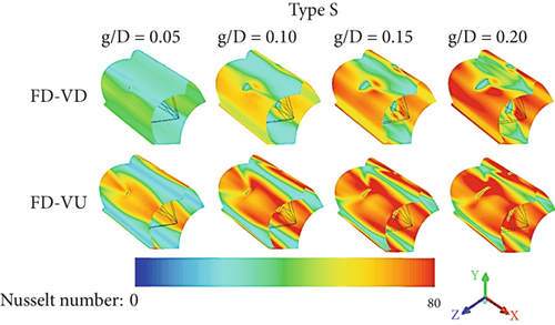
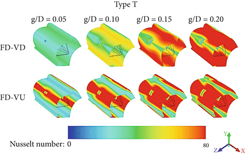
Upon examining the effects of changes in the P/D ratio on airflow and heat transfer, it is observed that the primary airflow structure and thermal characteristics remain similar to those at P/D = 1. However, as the P/D ratio increases, the intensity of the swirling flow decreases. This reduction in swirling flow intensity leads to a decrease in the severity of disturbances in the TH-BL and a corresponding reduction in the heat transfer rate.
5.2. Thermal Performance Analysis
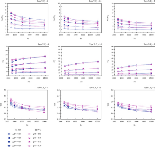
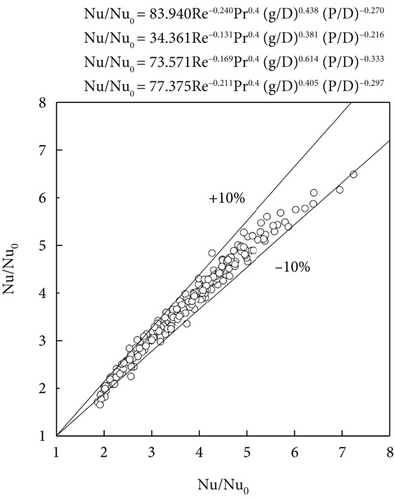
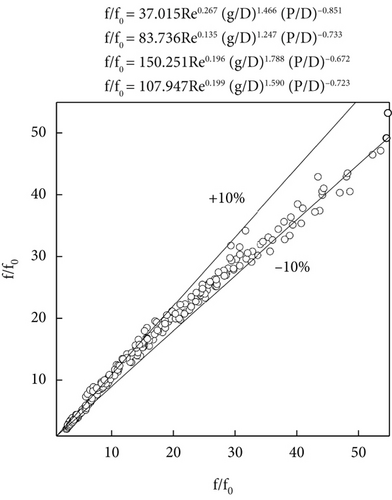
Figure 14a,b illustrates the evaluation of thermal performance in the heat exchanger tube with the installation of Type S and T XVB, respectively. The thermal performance analysis is presented through graphs showing the relationship between Nu/Nu0, f/f0, and TEF with respect to the Re. In all case studies, the values of Nu/Nu0 and TEF show a decreasing trend as the Re increases. The installation of the XVB significantly affects the heat transfer rate, which is consistently higher than that of a smooth, empty tube, with Nu/Nu0 values exceeding 1 in all cases, similar to the TEF values. The installation of the XVB not only enhances the heat transfer rate but also leads to an increase in pressure drop across the tube, particularly at higher flow obstruction ratios. The value of f/f0 shows a slight increasing trend as the Re increases.
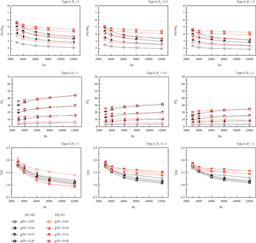
For Type S XVB, it is observed that at all values of the pitch ratio, the FD-VU results in a higher Nu ratio compared to the FD-VD when considering the same flow obstruction ratio. With achieves ranging from 2.28% to 39.07%, the FD-VU offers a higher heat transfer rate than the FD-VD. The case study with g/D = 0.20, P/D = 1, and FD-VD has the greatest Nu/Nu0 value, 5.71. Compared to P/D = 1.5, the heat transfer rate at P/D = 1 is 3.47% to 14.84% greater, and at P/D = 2, it is 7.14% to 22.88% higher. Similarly, the heat transfer rate at P/D = 1.5 is 3.22% to 9.60% higher than at P/D = 2. The ratio of Nu/Nu0 ranges from 2.10 to 5.59, 1.95 to 4.99, and 1.87 to 4.56 for P/D values of 1, 1.5, and 2, respectively, in the FD-VD. For the FD-VU, the ratio of Nu/Nu0 ranges from 2.65 to 5.71, 2.49 to 5.11, and 2.41 to 4.72 for P/D values of 1, 1.5, and 2, respectively. When considering the S-type XVB, most case studies indicate that the FD-VU exhibits higher values of f/f0 compared to the FD-VD. The difference in f/f0 is particularly noticeable in the Re range of 3000 to 6000, with the largest difference being 36.63% at a Re of 3000. For Re greater than 6000, f/f0 values are very similar across all FDs and pitch distances. The increase in the g/D ratio and the decrease in the P/D ratio result in a trend of higher friction coefficients due to the increased strength of the swirling flow, as explained in the flow behavior section. At g/D = 0.20 and P/D = 1, the maximum friction coefficient ratio is noted. The f/f0 values at P/D = 1 are higher than those at P/D = 1.5 and 2, with differences of 20%–81% and 36.11%–28.23%, respectively. At P/D = 1.5, the f/f0 values are higher than those at P/D = 2, with a difference of 9.38%–24.16%. According to the study’s findings, adding XVB to the heat exchanger raises the pressure drop and the rate of heat transfer. Therefore, the assessment of the benefits of XVB should be conducted at the same driving power level, which is presented in the variable known as TEF. In comparison to a smooth, empty pipe, the installation of XVB in the heat exchanger has a beneficial impact on the rise in heat transfer rate and thermal performance, as evidenced by the TEF value being more than 1 in all case studies. The maximum TEF value for type S XVB is 2.06 at g/D = 0.05 and P/D = 1, with FD-VU as the FD.
For the Type T XVB, at g/D = 0.05 and 0.10 with the FD-VD, the heat transfer rate is superior to that of the FD-VU direction. However, at g/D = 0.15 and 0.20, the graphs of Nu/Nu0 for both FDs intersect in some areas and overlap in others. The decrease in the P/D value and the increase in the g/D value contribute to enhanced swirl intensity, leading to an increased heat transfer rate. At P/D = 1, the heat transfer rate is greater than that at P/D = 1.5 and 2, with increases of 3.73%–19.55% and 8.56%–28.97%, respectively. At P/D = 1.5, the heat transfer rate is higher than at P/D = 2, with an increase of 2.51%–15.63%. For the FD-VD, the values of Nu/Nu0 are 2.20–6.95, 2.02–5.88, and 1.92–5.09 at P/D values of 1, 1.5, and 2, respectively. In the FD-VU, the values of Nu/Nu0 are 2.81–7.24, 2.63–6.03, and 2.54–5.29 at P/D values of 1, 1.5, and 2, respectively. The heat transfer rate reaches its maximum value of 7.24 times that of a smooth, empty pipe, achieved in the case study with g/D = 0.20, P/D = 1, and FD-VU. When considering the f/f0 values for Type T XVB, it is found that they are similar across most case studies, except in the case study where P/D = 1 at Re between 3000 and 6000. The maximum difference in f/f0 between the two FDs is 30%. A decrease in the P/D value and an increase in the g/D value result in a higher friction coefficient ratio. The f/f0 value at P/D = 1 is greater than those at P/D = 1.5 and 2, with increases of 11.30%–35.55%, 28.61%–44.92%, and 10.14%–32.99%, respectively. When considering the FD-VD, the f/f0 values range from 3.64 to 54.77, 2.92 to 48.58, and 2.60 to 38.86 at P/D values of 1, 1.5, and 2, respectively. With values ranging from 4.70 to 58.01, 3.63 to 46.94, and 3.18 to 38.06 times for the FD-VU at P/D ratios of 1, 1.5, and 2, respectively, the friction coefficient ratio is also higher than that of a smooth, empty tube. In the case study with g/D = 0.05, P/D = 1, and FD-VU, the greatest TEF value is 2.27.
Figure 15 demonstrations the comparison of the Nu/Nu0, f/f0, and TEF values for both types of XVB at P/D = 1. At g/D = 0.05, the values of Nu/Nu0 and f/f0 for both FDs are similar for both types of XVB. For the FD-VD at g/D = 0.10 and 0.15, the Nu/Nu0 graphs intersect, indicating that both types of XVB yield comparable heat transfer rates at these points. However, at g/D = 0.20, Type T XVB achieves a greater heat transfer rate than Type S. In the FD-VU, for g/D values between 0.10 and 0.20, the Nu/Nu0 graphs also intersect, leading to fluctuations where Type S shows higher or lower heat transfer values than Type T at different points. Type T XVB shows greater values than Type S for the f/f0 values at g/D = 0.15 and 0.20. At a Re of 3000, Type T XVB yields the maximum TEF value throughout both FDs.
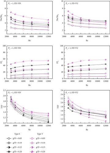
Figure 16 presents the graph of TEF contours showing the highest values for each type of XVB and FD. This graph provides valuable insight into the optimal combinations of g/D and P/D values for enhancing thermal performance. By analyzing the contours, designers can determine the most effective configurations for each type of XVB, which can then be applied to various industrial design applications. This allows for better customization and selection of XVB designs to maximize heat transfer performance while considering flow resistance and pressure drop.
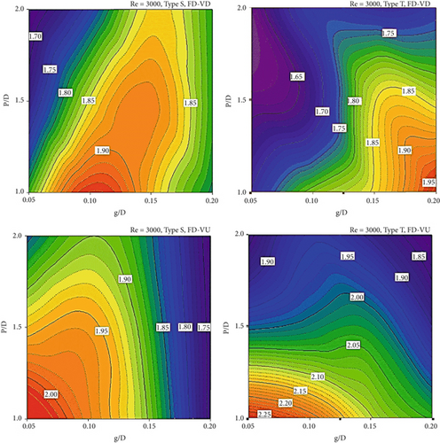
Table 1 presents a comparison of the maximum TEF values obtained from the present study and those reported in previous research. Although the control and assisting parameters vary across the studies and are not entirely within the same range of investigation, the data still provide a clear indication of the performance trends associated with each type of vortex generator. The table reveals that the use of combined vortex generators [6, 23] results in significantly higher TEF values compared to the conventional twisted tapes and wire coils commonly employed to enhance heat transfer in circular tubes. Among the configurations evaluated, the XVB demonstrates superior TEF performance.
| Authors | Vortex generator type | Maximum TEF |
|---|---|---|
| Present work | X-V baffle | 2.27 |
| Crespo-Quintanilla et al. [6] | Combined twisted tubes and twisted tapes | 3.06 |
| Wang et al. [9] | Twisted tape | 1.41 |
| Göksu [10] | Twisted tape | 1.535 |
| Farhadi et al. [16] | Twisted tape | 0.99 |
| Luo et al. [17] | Twisted tape and helical coiled wire | 1.31 |
| Wang et al. [19] | Helical coiled wire | 1.28 |
| Yao et al. [20] | Helical coiled wire | 3.78 |
| Feng et al. [23] | Rectangular wire coil and twisted tape | 2.13 |
| Keklikcioglu and Ozceyhan [27] | Conical wire coils | 1.62 |
| Chompookham et al. [28] | Serrated wire coil | 1.41 |
| Wang et al. [31] | Conical braided wire | 1.4 |
Furthermore, when considering stability in operation and ease of fabrication, the XVB, twisted tape, and wire coil exhibit comparable levels of manufacturing complexity, durability, and ease of installation.
6. Conclusion
- •
The results reveal that the installation of XVBs induces swirling flow within the tube, enhancing thermal performance by thinning the TH-BL and improving fluid mixing. Increased blockage ratios and reduced pitch ratios were found to intensify the swirling motion and, consequently, the heat transfer rate.
- •
Two XVB designs, Type S and Type T, were evaluated. The Type T XVB demonstrated superior thermal performance, especially at higher blockage ratios, albeit with an accompanying increase in pressure drop. The maximum TEF of 2.27 was achieved using the Type T XVB at g/D = 0.05, P/D = 1, and FD-VD. Under these conditions, the heat transfer rate exceeded that of a smooth tube by more than 7.24 times.
- •
The findings contribute to the design and optimization of vortex generator configurations in heat exchangers and offer valuable guidance for enhancing thermal performance in practical industrial applications.
Nomenclature
-
- FD-VD
-
- flow direction: V-downstream
-
- FD-VU
-
- flow direction: V-upstream
-
- XVB
-
- X-V baffle
-
- TEF
-
- thermal enhancement factor ()
-
- TBLD
-
- thermal boundary layer disturbance
-
- TH-BL
-
- thermal boundary layer
Symbols
-
- D
-
- tube diameter (m)
-
- f
-
- friction factor, friction loss
-
- g
-
- XVB thickness (m)
-
- h
-
- convective heat transfer coefficient (W m−2 K−1)
-
- k
-
- thermal conductivity (W m−1 K−1)
-
- L
-
- numerical model length/periodic length
-
- Nu
-
- Nusselt number
-
- p
-
- static pressure (Pa)
-
- P
-
- pitch spacing (m)
-
- Re
-
- Reynolds number
-
- T
-
- fluid temperature (K)
-
-
- fluid mean velocity in tube (m s−1)
-
- ρ
-
- density (kg m−3)
Subscripts
-
- Zero
-
- smooth tube
-
- pp
-
- driving force
Conflicts of Interest
The authors declare no conflicts of interest.
Funding
The authors received no financial support for the research, authorship, and/or publication of this article.
Acknowledgments
The authors would like to thank Prof. Dr. Pongjet Promvonge for suggestions.
Open Research
Data Availability Statement
Data is available on request due to privacy/ethical restrictions.


