A Spaceborne Ka-Band Earth-Coverage Phased Array Antenna Based on DBF-Shared Subarray for LEO Communications
Abstract
A spaceborne Earth-coverage phased array (ECPA) antenna at Ka-band is proposed for low-Earth orbit (LEO) satellite applications, which is based on digital beamforming (DBF) partially shared subarray architecture to implement two stages of DBF. By taking into account the effects of mutual coupling in active element pattern optimization, a new method to obtain an Earth-matched beam of the equivalent element of the ECPA is presented, in which the DBF-shared subarray, segmental shaping technique, and differential evolution algorithm are utilized to achieve Earth-coverage characteristic for the ECPA. Both the design method and the principle of DBF partially shared subarray for grating lobe suppression are presented. Moreover, a 16-element DBF-shared subarray with a shared ratio of 4:1 obtaining an Earth-matched beam pattern is designed, optimized, and verified by full-wave simulation in Ansys Electronics Desktop. Taking the DBF-shared subarray as the equivalent element, an ECPA including 40 DBF-shared subarrays is also designed and simulated. Numerical results demonstrate that the proposed ECPA has excellent performance of Earth-coverage scanning to compensate for the satellite communication link variation caused by path loss variation during beam scanning for LEO applications. In addition, the ECPA has the advantages of a low sidelobe level better than −20 dB as well as grating lobe suppression.
1. Introduction
In recent years, phased array antennas have emerged as the preferred solution for satellite communications on account of their advantages such as fast beam steering, high gain, multibeams, and high flexibility [1, 2]. In low-Earth orbit (LEO) satellite applications, path loss is directly proportional to the range from the spacecraft to the ground user terminals. Alternatively, path loss is minimized when the ground user is at the satellite nadir direction, incrementally increasing as the user deviates from the satellite boresight due to greater separation from Earth’s surface. To compensate for varying path loss between different ground users and satellites, a kind of phased array antenna on the satellite with Earth-coverage scanning characteristics is urgently desired to provide consistent communication links to any illuminated point on the Earth during beam scanning.
The isoflux beam antennas with Earth-matched radiation patterns provide a potential candidate to make a good match between the antenna gain and space loss by complicated design. In other words, these antennas maintain a relatively constant power density within the coverage area. This means that the signal strength remains consistent regardless of the distance from the antenna, resulting in a more predictable and reliable communication environment. However, isoflux beam antennas exhibit low gain with fixed coverages and cannot perform fast and agile beam steering [3–8]. The SpaceX system partially compensates for scanning gain variation by switching antenna elements on and off at certain steering angles [9], and the phased array scanning gain variation still cannot be adaptively matched to path loss changes during beam scanning. A design of isoflux scanning digital phased array for geostationary satellites was proposed in [10]. Nevertheless, this study only considers isoflux beam shaping under limited scan conditions, and the computational complexity of the phased array significantly increases for large-scale phased arrays with a large number of elements due to the completely shared subarray architecture, which enables the motivation of this work.
This paper proposes a design of a linear Earth-coverage phased array (ECPA) antenna for LEO satellite payloads operating at Ka-band with a −45∘ ≤ θ ≤ 45∘ scanning range. In view of the fact that a reasonable design of the radiation pattern variation of the phased array element within the scanning range is essential to control scanning gain variation, a novel technique achieving an isoflux-shaped beam for the equivalent element of the ECPA to realize Earth-matched scanning characteristic for LEO satellites is presented, which is achieved by utilizing digital beamforming (DBF) partially shared subarray architecture with a shared ratio of 4:1. Sharing subarray apertures with adjacent subarrays increases the radiating aperture size and the number of elements in the DBF-shared subarray, thus mitigating Earth-matched beam shaping challenges by enhancing degrees of freedom for optimization. To accomplish the challenging task of obtaining beam optimization within a 90° beamwidth, a segmental shaping method has been developed to achieve the Earth-matched beam shaping in segments, and the corresponding excitation coefficients of each segment can be flexibly controlled through DBF to reduce the complexity of the feed network in analog beamforming (ABF). Specifically, the scanning gain of the ECPA is minimized at the nadir point without scanning, ascending with the increase of the beam scanning angle, realizing good compensation for link loss resulting from path loss variation during beam scanning, and demonstrating Earth-coverage scanning characteristics during scanning. Furthermore, the ECPA exhibits low sidelobe and grating lobe suppression, mitigating interference from other systems. The primary contributions of this work are as follows. First, a method for beam shaping optimization within segmented angle ranges using a 16-element subarray is proposed. This approach enables the generation of Earth-matched beams over a 90° range, significantly reducing the complexity associated with optimizing wide Earth-matched beams. Second, a reconfigurable DBF partially shared subarray architecture is introduced, with beam reshaping accomplished by reconfiguring the amplitude and phase excitation of the elements in the shared subarray to generate Earth-matched beams in different angle ranges. Finally, a method is also proposed to suppress grating lobes within the scanning range of the ECPA by employing the DBF-shared subarray.
This paper is organized as follows. Section 2 presents the design of the DBF partially shared subarray architecture and the design of the ECPA. In Section 3, numerical results of the DBF-shared subarray and ECPA are presented. Finally, a conclusion is summarized in Section 4.
2. Design of the ECPA
2.1. Design of the DBF Partially Shared Subarray Architecture
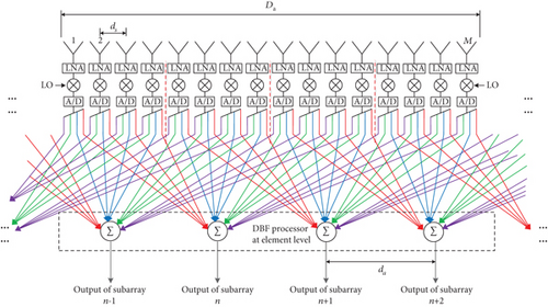
In the shared subarray architecture, the increase of radiation aperture and element number is implemented by sharing antenna elements of adjacent subarrays to facilitate beam shaping [11–14]. Similarly, the DBF-shared subarray can also employ additional radiating elements in subarray beamforming and can flexibly reconfigure the amplitude and phase excitation of the elements in the shared subarray. An architecture of the DBF partially shared subarray is shown in Figure 1. It can be seen that the DBF-shared subarray with M elements consists of radiating elements, low-noise amplifiers (LNAs), frequency converters, analog-to-digital (A/D) converters, and a DBF processor at the element level. The radiation aperture of an antenna element is shared by several neighboring subarrays. LNAs are directly integrated with the antenna radiators to minimize degradation of the gain-to-noise-temperature (G/T) ratio from beamforming network losses. After frequency conversion, the digitally sampled microwave signals are then beamformed with weighted values in the DBF processor at the element level.
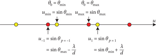
According to Equations (3) and (4), the step of DBF-shared subarray da can be selected reasonably.
2.2. Design of the DBF-Shared Subarray With Shared Ratio 4:1 and Earth-Matched Beam for LEO Satellite Optimization
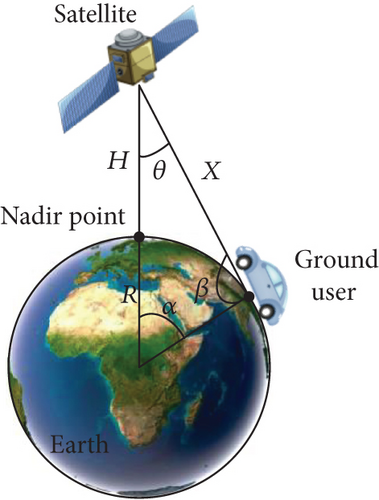
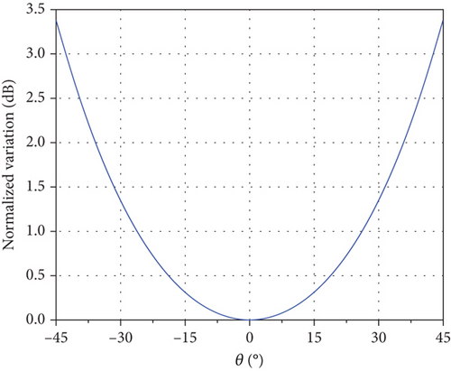
Using the Starlink satellite altitude H = 550 km as an example, the normalized space loss variation with a −45∘ ≤ θ ≤ 45∘ scanning range of the phased array can be obtained by using Equation (6), as described in Figure 3(b).
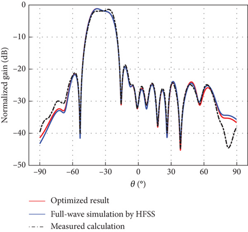
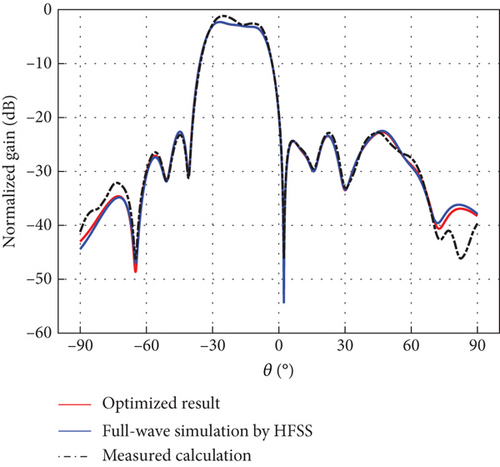
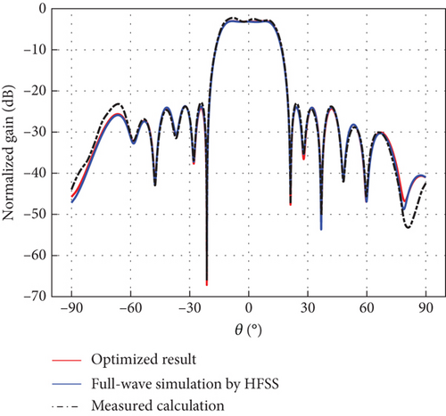
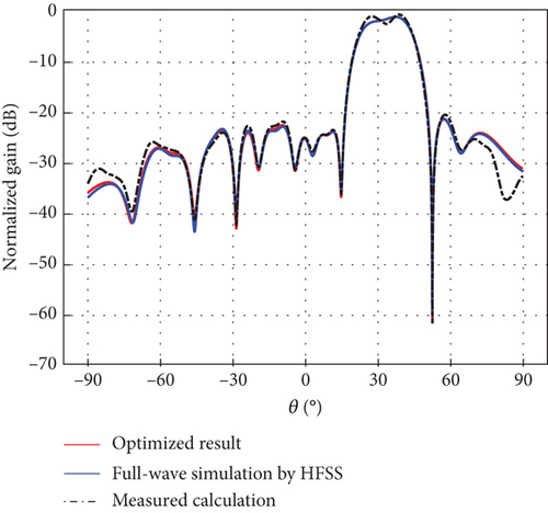
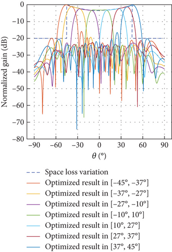
To facilitate Earth-matched beam optimization within −45∘ ≤ θ ≤ 45∘, a segmental shaping method is employed for ECPA isoflux scanning. The scanning range from −45° to 45° is partitioned into seven segments as shown in Figure 4: −45°, −37°; −37°, −27°; −27°, −10°; −10°, 10°; 10°, 27°; 27°, 37°; and 37°, 45°, respectively. The DBF-shared subarray comprising 16 radiating elements with an SR of 4:1 is illustrated in Figure 1. The element spacing is 0.5λ. Each radiating element is shared by four shared subarrays, and each shared subarray functions as a 16-element uniform linear array. The distance of the phase center between shared subarrays is 2λ, conforming to the design principle of avoiding grating lobes within the scanning range of all seven segments. Excitation coefficients can be obtained by numerical methods with active element pattern (AEP)–based optimization. In this way, the effects of mutual coupling among the elements have been taken into account during optimization.

2.3. Design of the ECPA
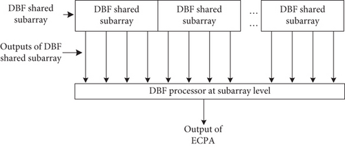
Based on the digital shared subarray design with 4:1 SR above, a scheme for the spaceborne ECPA antenna with the phase center of the digital shared subarray 2λ is proposed for LEO satellite communications. The ECPA consists of DBF-shared subarrays depicted in Figure 1 and a DBF processor at the subarray level presented in Figure 5. Each DBF-shared subarray functions as an equivalent element of the ECPA, and the common port of the DBF-shared subarray is connected to the DBF processor at the subarray level for secondary beamforming with a weighted value of shared subarray to achieve low sidelobe and beam scanning of overall DBF phased array. Specifically, the DBF-shared subarray has seven sets of excitation coefficients, corresponding to the seven scanning range segments. During beam scanning, the excitation coefficients of the DBF-shared subarray can be flexibly selected for DBF according to the required segmented scanning range.
-
Algorithm 1: Excitation coefficient selection programming.
-
1: switch scanning angle Theta
-
2: case -45°≤Theta<-37°
-
3: = excitation coefficients of [-45°, -37°];
-
4: case -37°≤Theta<-27°
-
5: = excitation coefficients of [-37°, -27°];
-
6: case -27°≤Theta<-10°
-
7: = excitation coefficients of [-27°, -10°];
-
8: case -10°≤Theta<10°
-
9: = excitation coefficients of [-10°, 10°];
-
10: case 10°≤Theta<27°
-
11: = excitation coefficients of [10°, 27°];
-
12: case 27°≤Theta<37°
-
13: = excitation coefficients of [27°, 37°];
-
14: case 37°≤Theta≤45°
-
15: = excitation coefficients of [37°, 45°];
-
16: end switch
3. Results and Numerical Simulations
3.1. Results of the DBF-Shared Subarray Simulation and Verification
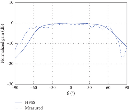
The element radiation pattern is critical for controlling scanning gain variation in phased array antennas. Thus, a DBF-shared subarray with a radiation pattern consistent with the space loss variation law in Figure 3(b) can be designed as an equivalent element of the ECPA to achieve Earth-coverage scanning characteristics. The DBF partially shared subarray proposed in this paper employs a circularly polarized (CP) ring microstrip antenna at 30 GHz depicted in Figure 6 and Table 1 as the radiating element for satellite communications, thereby minimizing potential multipath interference [15] and polarization mismatch [16]. As shown in Figure 6(a), the CP ring microstrip antenna is fed at a single center point and obtains left-hand circular polarization by a ring with two perturbation stubs printed on the top of the Rogers 5880 substrate. The CP ring antenna was fabricated and tested to validate the simulation design. The photograph of the prototype antenna is illustrated in Figure 7(b). The normalized radiation patterns of copolarized AEPs at 30 GHz are exhibited in Figure 6(b), the blue solid line stands for the full-wave simulation AEP, and the blue dotted line represents the measured result. It can be seen that the simulated AEP is following the measured radiation pattern.
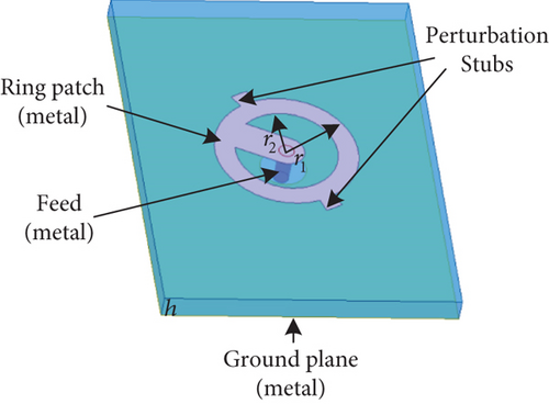
| Parameter | Length (mm) |
|---|---|
| r1 | 1.4 |
| r2 | 1 |
| h | 0.508 |


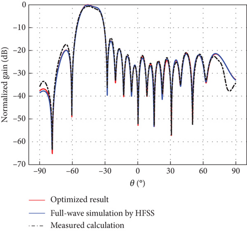
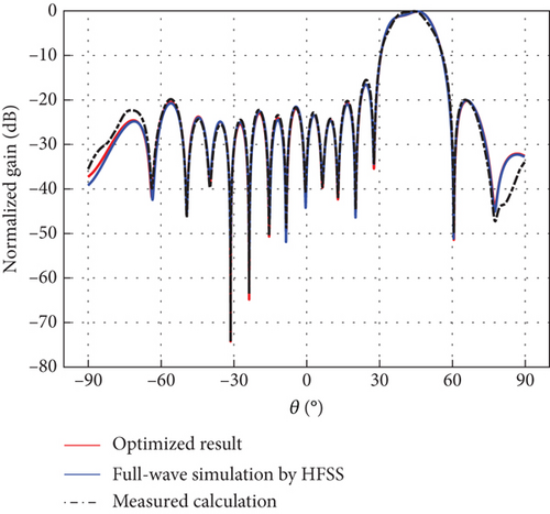
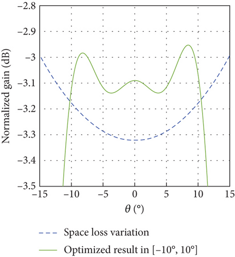
The differential evolution (DE) algorithm is an evolutionary algorithm used to solve global optimization problems in a continuous domain [17]. DE algorithm is simple and effective, and it has been applied to different array antenna problems and has shown excellent performance [18, 19]. The excitation coefficients generating an Earth-matched beam with low sidelobes for the DBF-shared subarray were obtained by the DE [20] over seven segmented scanning ranges: −45°, −37°; −37°, −27°; −27°, −10°; −10°, 10°; 10°, 27°; 27°, 37°; and 37°, 45°. Related results are described in Table 2 and Figure 8, respectively. For verification, full-wave electromagnetic simulations were performed in a high-frequency structure simulator (HFSS) of Ansys Electronics Desktop (EDT), with the full-wave simulation scenario of the linear CP ring microstrip array shown in Figure 7(a). To avoid the boundary effect of edge elements, a 24-element line array with an element spacing of 0.5λ was modeled; with beamforming achieved using the central 16 elements. Figures 8(a), 8(b), 8(c), 8(d), 8(e), 8(f), and 8(g) represent full-wave simulation results for the DBF-shared subarray with optimized weighted values in HFSS of Ansys EDT. Furthermore, a 24-element linear array same as the full-wave simulation linear CP ring microstrip array was fabricated as shown in Figure 7(b), and the AEP in the linear array was measured. Figures 8(a), 8(b), 8(c), 8(d), 8(e), 8(f), and 8(g) also represent comparisons of Earth-matched beams between optimized results, full-wave simulations by HFSS, and calculations by measured AEP with excitation coefficients in Table 2. As evidenced in Figure 8, numerically optimized results show excellent agreement with full-wave simulation results obtained from HFSS. The calculation results of the Earth-matched beam based on measured AEP can generally agree with the optimized ones. Due to fabrication and measurement errors, there is also some deviation in different scanning ranges between the measured and simulated results, although the overall trends are consistent. In addition, the main lobes of Earth-matched beams corresponding to the angle range are symmetric about the nadir. The optimized Earth-matched beams closely match the target pattern over the desired scanning ranges. Using the space loss variation of LEO satellites with an altitude of 550 km as a reference, the maximum deviation of optimized Earth-matched beam gain variation for shared subarray occurs within the range of −10∘ ≤ θ ≤ 10∘, which is only 0.24 dB, as shown in Figure 8(i).
| Element number | −45°, −37 | −37°, −27° | −27°, −10° | −10°, 10° | 10°, 27° | 27°, 37° | 37°, 45° | |||||||
|---|---|---|---|---|---|---|---|---|---|---|---|---|---|---|
| Magnitude (V) | Phase (deg) | Magnitude (V) | Phase (deg) | Magnitude (V) | Phase (deg) | Magnitude (V) | Phase (deg) | Magnitude (V) | Phase (deg) | Magnitude (V) | Phase (deg) | Magnitude (V) | Phase (deg) | |
| 1 | 0.5031 | 113 | 0.2482 | 203 | 0.0934 | 0 | 0.1251 | 173 | 0.0341 | 39 | 0.2369 | 117 | 0.4877 | 59 |
| 2 | 0.6725 | 241 | 0.0538 | 3 | 0.2002 | 123 | 0.1266 | 0 | 0.0867 | 134 | 0.0114 | 54 | 0.6105 | 294 |
| 3 | 0.8123 | 0 | 0.2731 | 170 | 0.2151 | 186 | 0.2248 | 21 | 0.2474 | 71 | 0.2972 | 175 | 0.7818 | 171 |
| 4 | 0.9511 | 120 | 0.5377 | 272 | 0.2047 | 221 | 0.2124 | 23 | 0.2600 | 0 | 0.5048 | 55 | 0.8764 | 54 |
| 5 | 0.9895 | 244 | 0.7619 | 13 | 0.1721 | 172 | 0.1673 | 74 | 0.2143 | 279 | 0.6805 | 308 | 0.9653 | 293 |
| 6 | 1 | 4 | 0.9087 | 106 | 0.4629 | 236 | 0.3394 | 145 | 0.3577 | 168 | 0.8326 | 217 | 1 | 169 |
| 7 | 0.9900 | 123 | 1 | 206 | 0.8900 | 268 | 0.7341 | 158 | 0.5786 | 73 | 0.9613 | 115 | 0.9498 | 48 |
| 8 | 0.8741 | 248 | 0.9842 | 306 | 0.9872 | 326 | 1 | 165 | 0.9140 | 9 | 1 | 20 | 0.8455 | 286 |
| 9 | 0.7361 | 12 | 0.8137 | 43 | 1 | 23 | 0.9489 | 162 | 1 | 305 | 0.9119 | 282 | 0.7279 | 164 |
| 10 | 0.5359 | 131 | 0.6577 | 137 | 0.8373 | 90 | 0.7619 | 160 | 0.9302 | 251 | 0.6465 | 184 | 0.5068 | 39 |
| 11 | 0.3438 | 261 | 0.3837 | 248 | 0.4724 | 160 | 0.3799 | 146 | 0.6824 | 191 | 0.4097 | 85 | 0.3346 | 276 |
| 12 | 0.1636 | 19 | 0.0117 | 0 | 0.2352 | 270 | 0.1441 | 94 | 0.3445 | 152 | 0.0489 | 18 | 0.1416 | 154 |
| 13 | 0.0301 | 216 | 0.0724 | 225 | 0.2672 | 14 | 0.2318 | 28 | 0.1536 | 156 | 0.0279 | 107 | 0.0451 | 286 |
| 14 | 0.1960 | 46 | 0.2122 | 346 | 0.3098 | 90 | 0.2266 | 19 | 0.2148 | 162 | 0.1883 | 0 | 0.1887 | 135 |
| 15 | 0.3461 | 174 | 0.1959 | 75 | 0.1339 | 150 | 0.1078 | 5 | 0.2770 | 100 | 0.2033 | 245 | 0.2980 | 0 |
| 16 | 0.4318 | 300 | 0.0964 | 201 | 0.0149 | 55 | 0.1141 | 171 | 0.1519 | 18 | 0.1562 | 124 | 0.4156 | 233 |

3.2. Results of the ECPA and Discussion
A linear ECPA including 40 DBF-shared subarrays with a shared ratio of 4:1 and the phase center spacing 2λ in Section 2 at 30 GHz is simulated and analyzed. Each DBF-shared subarray has 16 CP ring antenna elements with spacing 0.5λ. The total number of CP ring antenna elements is 172 according to Equation (8). For a uniform linear phased array with 2λ element spacing, there must be some grating lobes in visible space when scanning to −45° or 45°. However, for the ECPA based on the DBF partially shared subarray, the Earth-matched beam with low sidelobe of the shared subarray can be obtained by optimizing the excitation coefficients, effectively suppressing grating lobes and lowering phased array sidelobes during scanning. The ECPA has two layers of excitation coefficients for the DBF processor at different levels: excitation coefficients optimized by the DE method with Earth-matched pattern at the element level and weighted values obtained by a Taylor distribution at the subarray level. Depending on optimized excitation coefficients of shared subarray in Table 2 and weighted values with −20 dB Taylor weighting, the resultant beam scanning characteristics of ECPA and the comparison with the space loss variation are illustrated in Figure 9(a), which reveals the excellent Earth-coverage scanning characteristics and low sidelobe level performance batter than −20 dB to enhance the anti-interference capability of the satellite communication system further.
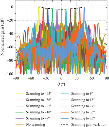
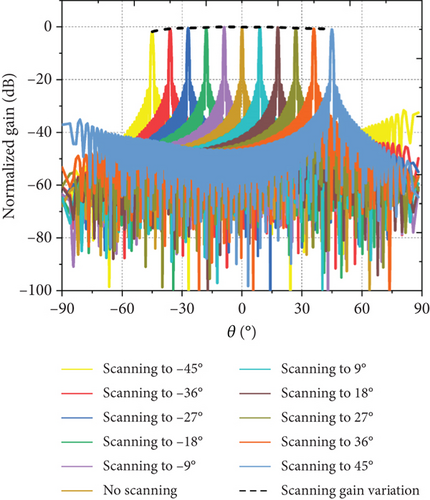
For a fair comparison of the scanning gain variation between the proposed ECPA and the conventional phased array during beam scanning, a conventional linear phased array (CLPA) is investigated with the same aperture as the ECPA consisting of 40 DBF-shared subarrays above. The CLPA has 148 CP ring antennas in Section 3 as element radiators with distance 0.58λ to avoid grating lobes in real space for scanning from −45° to 45°. Simulated results based on a Taylor distribution with −20 dB sidelobe are shown in Figure 9(b). Evidently, the gain of the CLPA decreases as the scanning angle increases, which contradicts the expected space loss variation. In contrast, when the ECPA scans within the range of −45° to 45°, the scanning gain related to the scanning angle follows the Earth-matched beam variation of the optimized DBF-shared subarray, tightly matching the space loss variation for LEO satellites illustrated in Figure 9(a). The maximum deviation between scanning gain variation and that of space loss is only 0.24 dB, which indicates that the scanning gain of the ECPA can well match the variation of space loss for LEO satellite communications, demonstrating Earth-coverage scanning characteristics.
Furthermore, a performance comparison of ECPAs with different shared subarrays for LEO satellites is presented in Table 3. The beamforming network of the shared subarray architecture in Reference [11] is based on ABF. It can only provide a fixed set of excitation coefficients for each element in the subarray, leading to a high difficulty in Earth-matched beam optimization, and only maintain low sidelobe characteristics outside the scanning range of −45° to 45°. However, for the ECPA employing the shared subarray of an SR 4:1 in Reference [11], the equivalent element of the phased array spacing is 2λ, and grating lobes will inevitably appear in the scanning range of −45∘ ≤ θ ≤ 45∘. Meanwhile, the ECPA can only suppress grating lobes outside −45∘ ≤ θ ≤ 45∘ and is incapable of suppressing those within the scanning range. For the ECPA using the DBF-shared subarrays proposed in this work, the Earth-matched beam can be optimized in segments and obtained by reconfiguring the amplitude and phase excitation coefficients of each element in the subarray, greatly reducing the beam optimization difficulty and suppressing grating lobes within the scanning range.
| Shared subarray architecture | SR | da | Earth-coverage scanning range | Optimization difficulty of Earth-matched beam | Beamforming of shared subarray | Reconfigurable beam of subarray | Grating lobe suppression in scanning range |
|---|---|---|---|---|---|---|---|
| Shared subarray in [11] | 4:1 | 2λ | −45° to 45° | Difficult | ABF | No | No |
| DBF-shared subarray in this work | 4:1 | 2λ | −45° to 45° | Easy | DBF | Yes | Yes |
4. Conclusion
A design of an ECPA antenna at Ka-band based on the DBF partially shared subarrays architecture for LEO satellite applications has been proposed. Besides, a novel method to obtain the Earth-matched beam for LEO satellites based on DBF-shared subarray with a SR of 4:1 has been presented. The ECPA with two stages of DBF has been designed, optimized, and simulated, respectively. Numerical results have indicated that the proposed ECPA is well characterized by Earth-coverage scanning, low sidelobe, grating lobe suppression, and the variation of scanning gain can well match that of satellite–ground path loss adaptively for LEO satellite communications, compensating for the communication link variation of different positions on the ground, thus providing potential prospects for the LEO satellite applications.
Conflicts of Interest
The authors declare no conflicts of interest.
Funding
This work is funded by the National Key Research and Development Program of China under No. 2019YFB1803200.
Acknowledgments
This study is funded by the National Key Research and Development Program of China under No. 2019YFB1803200.
Open Research
Data Availability Statement
The data used to support the findings of this study are included within the article.


