Dual-Band MIMO Dipole With Integrated Balun and Optimized Algorithm-Based Decoupling Structure
Abstract
This work presents a multiple-input/multiple-output (MIMO) antenna consisting of dipoles with integrated baluns and a parasitic element to reduce mutual coupling, which can cover two frequency bands. The configuration of the decoupling element is determined by using an optimization algorithm. The algorithm takes nine physical dimensions of the decoupling element as input and adjusts them by minimizing a cost function. One of these decision variables (DVs) is the number of decoupling element’s stairs (steps), which is a discrete parameter. In its simple form, the antenna cannot obtain proper isolation in the low-frequency band, which has been solved by employing a decoupling structure in the middle of the antenna. The experimental results show that the antenna has impedance bandwidths of 1.95–3.50 GHz and 3.98–5.67 GHz, providing minimum isolation of 13.1 and 19.5 dB in the low- and high-frequency bands, respectively. The ECC value is lower than 0.0038, and the peak gains are equal to 4.4 and 5.21 dB for the low- and high-frequency bands. The main contribution of this work is the design of the decoupling element, which, considering the antenna’s characteristics, has improved the antenna’s isolation by 12.4 dB only in the center of the low-frequency band.
1. Introduction
Wireless communication systems continue to advance due to the demand for faster data rates, expanded capacity, and enhanced spectral efficiency [1, 2]. As a convincing solution to meet these needs, multiple-input/multiple-output (MIMO) antennas covering a wide range of frequencies are considered a compelling option. By creating simultaneous communication over multiple frequency bands, they optimize the use of the spectrum and improve the antenna’s overall performance [3]. Among the different antenna configurations used in MIMO systems with multifrequency band coverage, dipole antennas are desirable due to their simplicity, compactness, and compatibility with various applications. Over the past few years, various types of MIMO antenna designs have emerged, and different techniques have been used to obtain proper performance for the antenna. This section will examine some of the most prominent designs presented in the last few years. In [4], a MIMO antenna using slot elements has been introduced, which has achieved the ability to cover two frequency bands in 5G and WLAN systems using optimization techniques. The frequency bands of 3.4–3.6 and 5.15–5.85 GHz are achieved in this work with minimum isolation of 19.8 and 16.7 dB between the elements in the lower and higher frequency bands, respectively. This design uses the decoupling technique, employing a slot and a parasitic element between the antennas. Another example of MIMO antennas is introduced in [5], in which dipole elements are used in its configuration. This antenna is designed to operate in the 2.4-GHz frequency band of WLAN systems, and a set of stubs with different lengths are responsible for reducing mutual coupling between the elements. The design mentioned covers the frequency band of 1.95–2.72 GHz, ensuring a minimum isolation of 15.2 dB between the ports. Two orthogonal monopole antennas have been introduced in [6], which use protruded stubs to enhance the isolation. This antenna offers an impedance bandwidth spanning from 1.40 to 9.60 GHz and provides isolation higher than 20 dB between the monopole elements.
Furthermore, other MIMO antennas have been introduced [7–9], whose radiation element is patch, and techniques such as DGS, slot, and parasitic elements have been used to increase isolation in their design. The mirror ordination of the ports in [10] guarantees the required isolation of this design. In this work, the 3.00–4.20 GHz frequency band is obtained with an isolation of more than 25 dB between the slot antennas. In addition to the mentioned cases, other designs of MIMO antennas have been presented in recent years, whose radiation elements include monopole [11], patch [12], and quasi-Yagi antennas [13]. These antennas have used the techniques of applying parasitic elements and dissimilar elements to create isolation.
Improving the isolation between antenna elements is one of the critical challenges in the design of MIMO antennas. This challenge becomes more highlighted when the MIMO antenna has multiple frequency bands [4, 13]. Because the behavior of the parasitic element as a decoupling element in the antenna configuration will be different at different frequencies, it seems necessary to use optimization algorithms so that they can efficiently improve the performance of the MIMO antenna [8, 10]. On the other hand, an optimization algorithm can be employed to improve the isolation while preserving the distinct electromagnetic properties of each antenna. So, using an optimization algorithm facilitates and improves the structure of a MIMO antenna design [14].
In this work, the introduced MIMO antenna has two dipole elements with balun feeding, which are positioned side by side in a horizontal orientation. A key characteristic of this antenna is its ability to operate across two frequency bands, specifically from 1.95 to 3.50 GHz and from 3.98 to 5.67 GHz, while the isolation between the antenna ports in the first frequency band is above 10 dB and in the second frequency band is more than 19.5 dB. In this way, there is a need for a decoupling element that can improve the isolation of the antenna only in the first frequency band but operation in both frequency bands does not alter the other characteristics of the antenna. Thus, the presented design utilizes the “surrogate” optimization algorithm, optimization for global minimization of time-consuming objective functions, to create the decoupling element. This element is in the form of stairs, and the optimization algorithm takes its physical properties as input. Then, the algorithm enhances the isolation of the first bandwidth by evaluating and minimizing the defined cost function. Maintaining other electromagnetic properties of the MIMO antenna is necessary during the optimization process.
2. Dual-Band Dipole Antenna With Integrated Balun
The first phase of the proposed antenna design is the introduction of a dipole antenna with the ability to cover two frequency bands. Since dipole antennas are known as balanced loads, balun structures are used to correctly connect them to the coaxial cable, which is an unbalanced transmission line. The balun used in this design is of the integrated balun type, which has been very popular in the design of printed dipole antennas in recent years [15–19]. Due to the physical length of the arms, dipole antennas can work in a specific frequency range. However, in the design presented in this work, modifications were made to the dipole arms, and two operating ranges were obtained for the antenna. Figure 1 shows the proposed dual-band dipole antenna configuration.
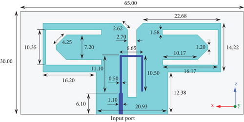
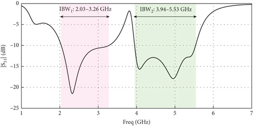
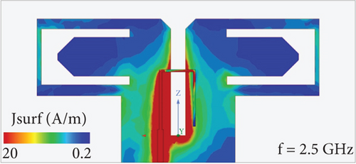
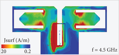
This antenna is accomplished on a Rogers RO4003 substrate with a permittivity of 3.55 and a thickness of 0.508 mm. The overall dimension of this antenna is 30 × 65 mm2, and it is fed from the end by an SMA connected to a coaxial cable. The dipole antenna consists of an Γ-feed, a slot line, and dipole arms. The input signal is delivered through the SMA to a tapered microstrip line at the beginning of the Γ-feed, and in the balun structure, this signal reaches the horizontal part of the Γ-feed through a slot line. Power transmission occurs in this section, and the input signal is conveyed to the dipole arms of the antenna through magnetic coupling. Figure 2 demonstrates the S11 response of the proposed dual-band dipole antenna. As depicted in this diagram, the suggested dipole antenna features two impedance bandwidths of 2.03–3.26 and 3.94–5.53 GHz. Figure 3 illustrates the simulated surface current distributions on the proposed dipole antenna for 2.5 and 4.5 GHz. Examining surface current distributions on an antenna can provide valuable insights into its performance and behavior. The antenna’s surface current distribution shows that the surface currents’ concentration at 2.5 GHz frequency is on the dipole arms. At 4.5-GHz frequency, this concentration is more around the U-shaped slot on the dipole arms. Indeed, new paths have been created at 4.5 GHz for the antenna by making a U-shaped slot on the dipole arms.
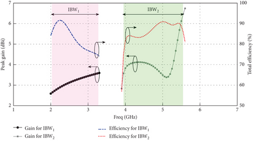
The simulated peak gain and radiation efficiency of the proposed dual-band dipole antenna are illustrated in Figure 4. The results show that the antenna has more than 85% radiation efficiency at 2.5 and 4.5 GHz frequencies. Furthermore, the presented dipole antenna achieves peak gains of 3.8 and 6 dB in the low- and high-frequency bands, respectively.
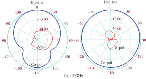
The normalized radiation patterns of the proposed dual-band antenna in Figure 5 demonstrate that the dipole antenna exhibits consistent unidirectional radiation in both operating bands. Also, the cross-pol level in both frequency bands is lower than 28 dB.

3. Dual-Band MIMO Dipole With Decoupling Structure Using Optimization Algorithm
This paper’s second phase is designing a MIMO antenna using the dual-band dipole introduced in the previous section. At this step, two dual-band dipoles are placed horizontally next to each other at a distance of 29.5 mm from each other. The most critical challenge of designing MIMO antennas is the issue of mutual coupling between MIMO antenna elements. Mutual coupling affects the correlation between different antenna elements in a MIMO system. A high level of mutual coupling can increase correlation, reducing the effectiveness of spatial multiplexing and degrading the system’s capacity to transmit multiple independent data streams simultaneously.
Furthermore, mutual coupling exacerbates interference between antenna elements, mainly in closely spaced arrays. Therefore, the system’s performance is degraded with cochannel interference, which reduces the signal-to-interference-plus-noise ratio (SINR). As a result, controlling the mutual coupling between MIMO antenna elements by interference mitigation techniques can more effectively overcome unwanted signals and enhance overall system capacity. The configuration of the dual-band MIMO antenna with a decoupling element is presented in Figure 6.
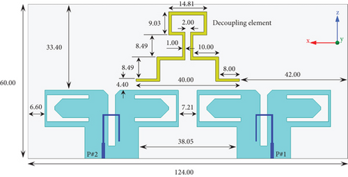
In this design, a stair-shaped decoupling structure is added to the upper part of the antenna between the dipoles. The basic point in the design of the proposed MIMO antenna without a decoupling element is that the isolation between the antenna elements is acceptable in the high-frequency band but needs to be improved in the low-frequency band. As shown in Figure 7, this issue is addressed by incorporating a decoupling structure. Based on the findings, the utilization of the decoupling structure enhances the antenna’s isolation by 12.4 dB only in the center of the low-frequency band. To create a better understanding of how to design the decoupling element, its optimization process using the optimization algorithm is investigated in this section.
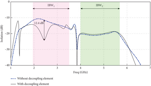
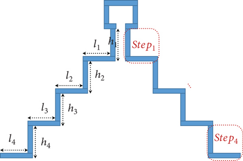
As shown in Figure 7, the proposed MIMO structure presents low isolation between MIMO antenna elements at the low-frequency band (IBW1). As a result, a novel parasitic symmetric isolation structure is proposed to improve isolation in this band. There can be up to four steps in this “stair-shaped” structure to improve the isolation at IBW1 so as to have a minor effect on S11 in the first band (Figure 8).
The S12(2.5)’s weight is set three times the S11(2.5)’s weight to achieve the main objective of the optimization process, enhancing isolation between MIMO elements. Therefore, w1 is set to unity. The optimization algorithm should meet a predetermined objective by minimizing Fc.
Figure 9 presents the working flow of the proposed method to enhance isolation between MIMO antenna elements. The algorithm updates the structure after initializing the DVs based on the boundary conditions. In CST, the updated structure is simulated, while in MATLAB, the defined cost function is evaluated. The algorithm checks Equation (2) for validity if Equation (1) is satisfied by the boundary conditions and simulated scattering parameters. The algorithm updates and saves the cost function value, scattering parameters at determined frequencies, height, length, and NFE (NFE is the number of function evaluations) when Equation (2) is satisfied, and the new cost function is less than the old one. After that, the optimization algorithm checks to see if the stopping condition has been met to stop the optimization process. The optimization algorithm starts initializing DVs from scratch if any conditions are unmet.
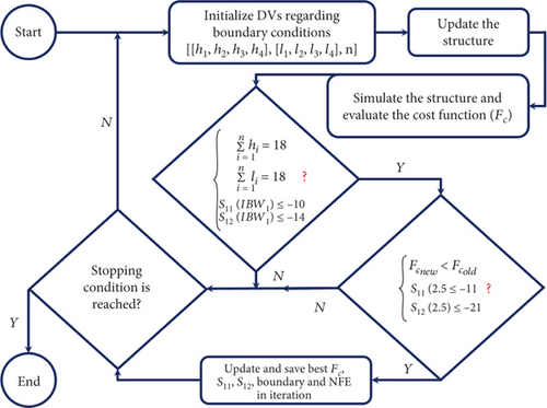
Figure 10 shows the progress of optimization for enhancing isolation between MIMO elements. The ninth DV indicates the number of steps that were selected for isolation enhancement, which is equal to two. It follows that the sum of [h1, h2] and [l1, l2] DVs, respectively, should satisfy Equation (1). In addition, this figure provides an estimate of the cost function based on the weights determined for scattering parameters.
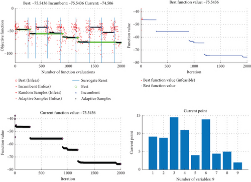
Figure 11a represents the most optimal scattering parameters, including the lowest cost function value and the selected number of steps for isolation enhancement (Figure 11b). It is important to note that scattering parameters at the beginning of iterations produce better results (Figure 11a). These values, however, are generated by DVs, which are not feasible with respect to the conditions of the optimization problem, which has been defined inside the optimization program.
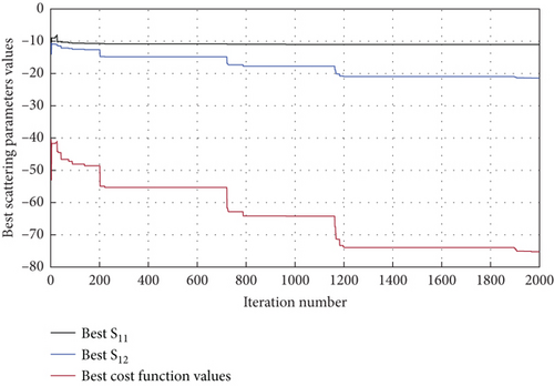
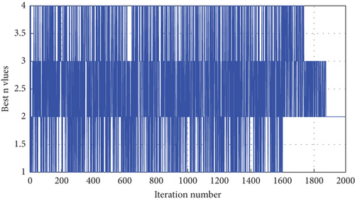
Figure 11b represents the number of steps converged into two to achieve the highest possible isolation between MIMO elements.
4. Comparison of Simulation and Measurement Results
The dual-band MIMO dipole antenna with the decoupling element proposed in this work was fabricated after optimization steps. It was tested and measured in the laboratory by an Agilent E8363C Vector Network Analyzer. Figure 12a shows the fabricated prototype of the proposed MIMO antenna. Also, in this figure, the test process of S-parameters and their radiation properties are demonstrated in Figure 12b,c, respectively. The measured results approve that the proposed MIMO antenna has two impedance bandwidths of 1.95–3.50 and 3.98–5.67 GHz. Furthermore, the fabricated antenna provides isolations of more than 13.1 and 19.5 dB in the low- and high-frequency bands, respectively. The comparison between the simulated and measured S-parameters and isolation of the dual-band MIMO dipole antenna with the decoupling element are plotted in Figure 13.
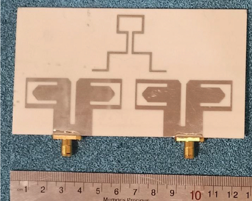
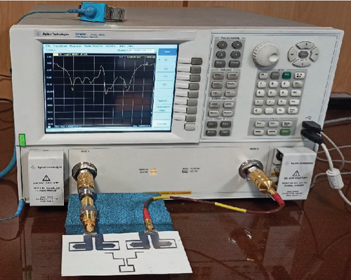
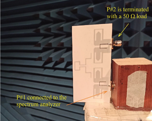
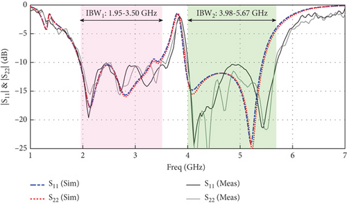
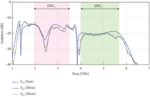
Figure 14 shows the results of ECC and TARC parameters for the MIMO antenna proposed in this paper. The experimental results confirm that the designed antenna has an ECC of less than 0.0038 in the frequency bands, and the TARC value within the antenna operating frequency bands averages approximately −5 dB.
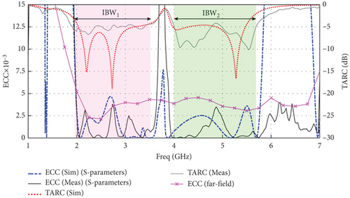
The far-field method, often regarded as a more accurate representation of ECC, calculates ECC based on the far-field radiation patterns of the antenna elements. This technique considers the spatial radiation characteristics, including the phase, amplitude, and directional behavior of each antenna element, which provides a more comprehensive view of the correlation in actual operating conditions.
The DG parameter can be close to 10 dB under favorable conditions, such as environments with multipath propagation. As a result of this level of improvement, there is a substantial mitigation of fading effects and an enhanced level of reliability of the wireless link. Another index worth checking for the correct operation of MIMO antennas is channel capacity loss (CCL). In MIMO antenna systems, CCL refers to the reduction in channel capacity resulting from interference, noise, fading, and other factors that affect wireless communication channels.
Figure 15 illustrates the measured and simulated performances of DG and CCL. According to the experiments, the DG value is almost 10 dB, and the CCL parameter is below 0.4 bits/s/Hz. Notably, the acceptable value for CCL in the design of the MIMO structure is 0.5 bits/s/Hz [21].
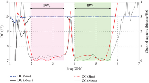
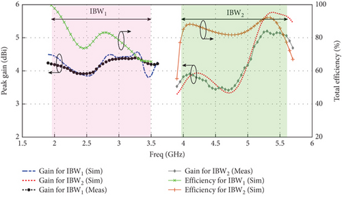
Figure 16 compares the simulated and measured peak gains of the proposed MIMO antenna with the decoupling element. According to the measurements, the peak gains of almost 4.4 and 5.21 dB for the low- and high-frequency bands have been obtained, respectively. Furthermore, the simulated radiation efficiency for the proposed dual-band MIMO dipole antenna with the decoupling element is plotted in Figure 16. As shown in this figure, the proposed dual-band MIMO dipole antenna achieves an average radiation efficiency of approximately 80% in the low-frequency band and 83% in the high-frequency band.
Also, the normalized H-plane and E-plane radiation patterns of the proposed MIMO antenna at 2.5 and 4.5 GHz are displayed in Figure 17 for experiment and simulation modes.
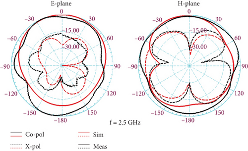

The results confirm that the proposed antenna has a stable radiation pattern with a unidirectional shape in the direction of the z-axes. It is noteworthy that due to the structural symmetry of the proposed antenna, the antenna radiation specifications are only measured in one of its ports. When testing the antenna, one of the ports by coaxial cable is connected to the spectrum analyzer, and the other antenna port is terminated by a standard 50-ohm load.
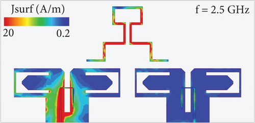
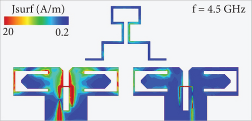
Additionally, Figure 18 plots the simulated surface current distributions on the proposed dual-band MIMO dipole antenna with the decoupling element at the center frequencies of antenna bandwidths. The observed phenomenon of surface current accumulation on the decoupling element only in the low-frequency band could be explained by the antenna system’s principle of resonance and impedance matching. Generally, antennas function most effectively when their physical dimensions are approximately resonant with the wavelength of the electromagnetic waves they are designed to transmit or receive. As the antenna observes a significant accumulation of surface currents on the decoupling element in the low-frequency band, the dimensions of the decoupling element are likely to be well matched to the wavelength, resulting in resonance and efficient energy transfer. A good impedance match between the antenna and the transmitter or receiver circuitry is critical for maximizing power transfer. The impedance matching in the low-frequency band is optimized, resulting in an efficient energy coupling between the antenna elements and the decoupling structure. In the high-frequency band, however, where surface currents are not as significant, impedance matching is not optimal, resulting in less efficient energy transfer and reduced surface current accumulation. On the other hand, the decoupling element is designed to isolate the antenna elements, reducing mutual coupling and improving antenna performance, particularly in MIMO systems where interference between antenna elements can lead to performance degradation. The effectiveness of the decoupling mechanism may vary with frequency, causing differences in the distribution of surface currents on the decoupling element between frequency bands.
A stair-shaped decoupling structure was chosen because of its ability to provide enhanced isolation between closely spaced MIMO antenna elements, particularly in the low-frequency band, where isolation was initially insufficient. By utilizing a stair-shaped structure, parasitic elements can be distributed at specific heights, providing flexibility for optimizing the physical dimensions of the decoupling structure. Through an optimization algorithm that adjusts the number and dimensions of the steps, this design can be fine-tuned in order to reduce coupling between the elements. Furthermore, stair-shaped structures provide an additional degree of freedom for adjusting parameters (such as step height, width, and number of steps) without affecting the antenna’s overall performance in other frequencies. Due to its versatility, the stair-shaped design was an ideal candidate for achieving low-frequency isolation while remaining simple to manufacture. We have adapted the stair-shaped decoupling structure for optimal isolation within the proposed dual-band frequency range.
The selection of the stair-shaped parasitic decoupling structure was guided by its ability to provide frequency-selective isolation through resonant behavior at the low-frequency band. This configuration was iteratively refined using a surrogate optimization algorithm to confirm the minimal impact on other antenna parameters. Also, the physical dimensions of each step in the stair-shaped decoupling element are designed to correspond to a fraction of the wavelength (λ) at the center of the lower operating frequency band. This configuration’s step lengths and heights are proportional to λ/4, making a resonant structure at the intended frequency. The spacing and arrangement of steps are optimized to reinforce this resonance, ensuring maximum energy cancellation along the mutual coupling path.
Furthermore, each step acts as a localized resonator that interacts with the electromagnetic fields of the adjacent dipole elements. This interaction leads to capacitive coupling from the close proximity between the steps and the dipoles. Inductive coupling is also achieved by establishing current paths through the metallic surfaces of the steps. In addition, the combined effect of these steps produces a frequency-selective response, with the structure exhibiting maximum isolation at its resonant frequency while minimizing its impact on other frequencies. Although the specific configuration yielding the desired results is not unique, its selection was driven by its simplicity and manufacturability and its ability to improve isolation without significantly affecting other performance parameters. It is theoretically possible to achieve similar results with different configurations, such as using slot-line structures, grounded stubs, or metamaterial-based elements. However, these alternatives often introduce complexities such as increased fabrication cost, altered antenna profile, or performance trade-offs at higher frequencies.
Furthermore, a surrogate optimization algorithm was used to refine the structure’s dimensions in order to align them with the target frequency while maintaining impedance matching, further highlighting the achievement of a balance between design simplicity and high performance. This work’s primary concern is narrowband isolation at the lower frequency band. However, it is worth noting that the isolation enhancement was deliberately optimized for the lower band’s center frequency due to the decoupling structure’s practical limitations. Regarding the narrowband nature of the isolation in the lower band, we acknowledge that the enhancement is focused on the band’s center frequency. This design decision addressed the most critical coupling frequencies while maintaining practical manufacturability and compactness. We agree that future research could explore ways to broaden the isolation bandwidth, such as integrating additional resonant elements or hybrid techniques.
In the final section of this paper, the features and results of this design are compared with similar works introduced in recent years in Table 1. In this table, in addition to essential antenna parameters such as bandwidth, gain, isolation, and ECC, the type of antennas presented in the comparison table and their decoupling techniques are also compared. The table shows that some references have low isolation [5, 12, 13], and some represent a high ECC between the antenna elements [4, 6, 8–10, 12, 13]. Also, most antennas in the comparison table are single band [5–12], and only the proposed work and [4, 13] are dual band. On the other hand, the gains of most table antennas are lower than those of the proposed work.
| Ref. | IBW (GHz) | Isolation (dB) | ECC | PG (dBi) | Size (mm 3) | Decoupling method | No. of band | Antenna type |
|---|---|---|---|---|---|---|---|---|
| [4] |
|
|
|
|
25 × 25 × 1.57 | Parasitic element + slot | Dual | Slot |
| [5] | 1.95–2.72 | > 15.2 | < 0.0037 | 6.28 | 100 × 50 × 38.6 | Parasitic element | Single | Dipole with integrated balun |
| [6] | 1.40–9.60 | > 20 | < 0.08 | 3.8 | 32 × 32 × 1 | Protruded strip | Single | Monopole |
| [7] | 2.50–2.55 | > 20 | < 0.003 | 6.1 | 150 × 100 × 0.8 | Grounded stubs + DGS | Single | Patch |
| [8] | 5.49–6.02 | > 33 | < 0.15 | 5.34 | 27.69 × 97 × 1.524 | Feeding along the slot + split in the ground | Single | Patch |
| [9] | 5.10–5.60 | > 30 | < 0.5 | 8.5 | 80 × 55 × 3.04 | Parasitic element + DGS | Single | Patch |
| [10] | 3.00–4.20 | > 25 | < 0.005 | 4 | 120 × 60 × 0.8 | Mirror ordination of the ports | Single | Slot |
| [11] | 3.40–5.00 | > 15.6 | < 0.002 | 5.21 | 120 × 70 × 20.2 | Parasitic element | Single | Monopole |
| [12] | 3.10–5.20 | > 10 | < 0.1 | 2.65 (Sim) | 35 × 35 × 1.57 | Two dissimilar antennas | Single | Monopole + patch |
| [13] |
|
> 15 | < 0.0785 | 4.6 | 120 × 50 × 0.76 | — | Dual | Quasi-Yagi |
| [22] | 22–50 | > 30 | < 0.05 | 8.6 | 36 × 28 × 0.8 | Metamaterial and DGS | Single | Monopole |
| [23] | 1.5–2.1 | > 17 | < 0.005 | 1 | 40 × 81.6 × 1.524 | Parasitic element | Single | Monopole |
| [24] | 12.0–18.0 | > 25 | < 0.002 | 5 | 50 × 26 × 0.8 | Mirror ordination of the antenna elements | Single | Monopole |
| This work |
|
|
|
|
124 × 60 × 0.508 | Parasitic element | Dual | Dipole antenna with integrated balun |
In addition, antennas with high gains have used more sophisticated decoupling techniques. However, only [5] and the proposed work have a dippel structure with integrated balun and display more appropriate behavior regarding radiation properties. Given all the parameters mentioned above, it can be concluded that the proposed dual-band MIMO antenna can be a good candidate for WLAN applications.
5. Conclusion
This work introduces a dual-band MIMO antenna with compact dimensions and high gain. The antenna comprises dipoles with integrated balun structures for its radiation elements. In the first phase, two dipole antennas are positioned in proximity to one another, producing a MIMO structure that covers two frequency bands but suffers from low isolation in the low-frequency band. This problem is solved by positioning a decoupling element between the dipoles. The employed decoupling element has a stair shape and is placed at the top of the dipoles. This work uses an optimization algorithm to obtain the dimensions and number of decoupling element stairs. The algorithm is aimed at optimizing the decoupling element’s structure to improve the isolation in the low-frequency band so that the other antenna parameters are not affected by its destruction. The inclusion of the decoupling structure enhanced the isolation of the antenna by 12.4 dB in the center of the low-frequency band, according to the results. The proposed MIMO antenna has impedance bandwidths of 1.95–3.50 and 3.98–5.67 GHz, which provides a minimum isolation of 13.1 dB in the low-frequency band and 19.5 dB in the high-frequency band. For both frequency bands, the ECC value is less than 0.0038, and the peak gains are equal to 4.4 and 5.21 dB, respectively.
Conflicts of Interest
The authors declare no conflicts of interest.
Author Contributions
Amir Hatamian: conceptualization, formal analysis, resources, software, writing–original draft. Javad Nourinia: methodology, validation, review and editing, supervision. Changiz Ghobadi: methodology, validation, review and editing, supervision.
Funding
This research received no specific grant from any funding agency in the public, commercial, or not-for-profit sectors.
Acknowledgments
Obtaining technical assistance from Urmia University’s Northwest Antenna and Microwave Research Laboratory (NAMRL) is gratefully acknowledged by the authors. Also, the authors would like to acknowledge the use of Grammarly, a generative AI-powered writing assistant, for language editing and proofreading during the preparation of this manuscript. Grammarly was used solely to improve the clarity, grammar, and readability of the text and did not contribute to the scientific content, data analysis, or interpretation of results.
Open Research
Data Availability Statement
The data that support the findings of this study are available from the corresponding authors upon reasonable request.


