The Effect of Preexisting Fracture Angles on Crack Propagation in Sandstone
Abstract
The fracture propagation on the rock causes failure and impacts the sustainability time of the structure. As part of the present work, sandstone with the variation of preexisting crack angle was simulated using the extended finite element method (XFEM). The crack propagation on sandstone has a preexisting fracture angle of 30°, 45°, and 60°, with an equivalent crack length. The impact of preexisting fracture angle on the possibility of crack propagation, failure mechanism, and displacement at a critical point of all models was studied. The numerical simulation revealed the crack angle of the model control vibration and its impact on the model’s seismic stability. The XFEM results are validated with reference to those available in the literature. Artificial neural networks (ANNs) are used for prediction by considering the training, testing, and validation process and analyzing prediction errors. The present simulation’s conclusion significantly supports the model’s displacement prediction with no crack propagation occurrence. In addition, by considering the preexisting fracture angle of a model, the load sustainability can be estimated.
Summary
- •
The impact of the preexisting fracture angle on crack propagation was studied.
- •
To recognize loading and unloading displacement by calling vibration mechanisms.
- •
The failure mechanism and displacement were studied.
- •
The results of the extended finite element method (XFEM) were validated with reference to the literature.
- •
The artificial neural network (ANN) is applied for integrated prediction.
1. Introduction
The displacement and different crack types in bedrock occur due to geostress [1], seismic loading [2], and the application of external forces from the construction process, such as pile nailing [3, 4]. The nonlinear differential displacement on the soil and rock accelerates the crack propagation. Due to the complicated geostress behavior, it is necessary to recognize the seismic stability of the rock stone under seismic loading.
The angle of the preexisting crack appears in different directions and lengths, and it varies in different parts of the bedrock in association with the shape of the rock, which is critical for load transferring [5]. The crack impacts underground structures such as tunnels [6] and the stability of soil-structure interaction [7], and leads to changes in earth structure seismic stability and instability [8]. The impact of the preexisting crack angle on the damage and failure of the sandstone model needs to be investigated. In addition, it is essential to analyze the influence of seismic acceleration on the displacement of critical points of the model.
Propagation of preexisting cracks causes failure of the earth’s structure. With an increase in the number of preexisting cracks in the earth’s structure, the seismic response and nonlinear displacement, strain, stress, vibration mechanism, and failure of the model change and lead to a reduction of the safety of the earth’s structure [9]. Numerous earth structures facing liquefaction cause settlement [10, 11]. Experimental and numerical simulations have been used to study the seismic response of the earth dam, causing liquefaction in the soil foundation and internal cracks on the earth dam due to nonlinear settlement. In the numerical simulation, the crack of the earth’s structure has not been simulated [12]. Appropriate numerical simulation is essential for the cracking of the earth structure model to understand the relationship between the crack and the settlement of the model.
The failure and damage progression in brittle rocks shows that sandstone’s brittle failure is associated with the mechanical properties of rock [13]. The crack initiation and propagation on sandstone are investigated by considering stress and strain development [14]. The fracture toughness of sandstone changes with stress and strain rate mechanism [15]; due to the stress and strain associated with the crack, it is necessary to investigate the strain and strain during the crack propagation.
Fracture damage and mode classification of rock were predicted using uniaxial compression [16, 17]. Several numerical and experimental studies have been conducted to assess crack coalescence [18, 19]. Following this excellent research work, the nondestructive works were proposed through the digital image used for crack analysis in the fracture behavior [20–22], as well as using precursory acoustic emission (AE) time series for forecasting catastrophic rupture in brittle rock and concrete. The damage developments in the samples are identified by the mixing of nondestructive tests of AE and digital image correlation (DIC) with uniaxial compression testing methods in real time [23–25]. Considering previous works, the finite element method is needed to analyze the crack propagation of the rock.
The seismic loading causes sudden failure by raising critical stress on the earth’s structure, concrete [26], and rock [27], with the appearance of single and multidirectional cracks [28]. Therefore, simulation of the damage and failure law for rock containing preexisting cracks under seismic loading is vital for predicting long-term sustainable underground structure construction. In view of engineering design, the impact of the crack angle on damage and failure law must be clearly understood by the geotechnical designer. In addition, the effect of the angle of the preexisting crack on displacement at a selected model point needs to be investigated.
In geotechnical engineering, differential displacement occurs due to factors such as the application of seismic load to the model [29], nonlinear soil structure interaction [30], the shape of the foundation when the model is subjected to the seismic loading [31], heat treatment [32], liquefaction [33], and cyclic high-speed (300 km/h) train loading applying to the soil foundation [34]. Considering these reasons for the development of differential displacement, the crack propagation shape due to the preexisting crack angle must be studied accurately.
Statistical analysis has been reported to predict and classify the geotechnical results obtained from the experimental and numerical simulation outcomes [35–38]. There are several statistical attempts to predict engineering phenomena [39–41]. The ANN supports enhancement prediction through training, testing, and validation of the prediction accuracy.
Using XFEM, the shape of crack propagation due to the initial status of the preexisting crack angle was studied, as well as its impact on the failure mechanism and displacement of the model. Additionally, the displacement associated with the initial status of the preexisting crack angle was predicted using ANNs.
- •
To evaluate the initial status of the preexisting crack angle in displacement of the model.
- •
To predict the displacement of the model by employing ANNs.
- •
To study multidirectional displacement at a point, recognizing them from loading and unloading displacement by calling them vibration mechanisms.
2. Method and Materials
Figure 1 demonstrates the entire numerical simulation and application of the statistical analysis process for predicting the displacement. Numerical modeling was conducted to design the clay landfill cover under seismic loading. The fracture’s angle, mechanical properties of the sandstone, and characteristics of seismic acceleration are the main parameters. In addition, the model’s failure mechanism, displacement in its selected critical point, and crack propagation are the model’s primary outcomes. These parameters have been considered according to the crack angle in the numerical simulation of the sandstone, which is subject to seismic loading in a single direction. In order to validate the results of the numerical simulation, the outcome of the simulation has been compared to available data in the literature. Table 1 illustrates the mechanical properties of the sandstone used in the numerical simulation. For all models, a single material type was selected.

| Poisson’s ratio, ν | Unit weight, γ (kN/m 3) | Modulus elasticity, E (MPa) | Length (L )/(mm) | Width (W )/(mm) | Thickness (h )/(mm) |
|---|---|---|---|---|---|
| 0.25 | 24 | 35,000 | 600 | 600 | 60 |
Figure 2 depicts the seismic acceleration of the Florina earthquake, which occurred on January 09, 2022. The earthquake had a magnitude of 5.5 MWW and a depth of 10.0 km. The seismic acceleration in the 0°, 90°, and 360° directions has a dissimilar vibration mechanism.
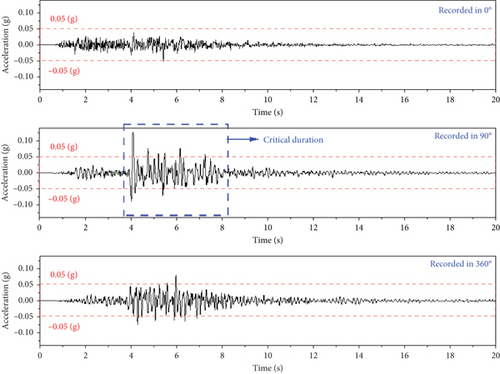
The model has been subjected to multidirectional seismic loading to simulate its boundary conditions accurately [44]. However, in the present work, the seismic acceleration was applied in a single direction for simplification. In addition, the critical duration in the 90° direction has been used in the numerical simulation.
Figure 3 demonstrates the Modified Mercalli Intensity (MMI) for the Florina earthquake with 5.5 MWW. The seismic station was used to estimate the shaking intensity of the earthquake at a specific distance, as shown in Figure 3. This effective shaking intensity of the earthquake impacts structures and objects and causes damage. According to the prediction and observation from data collection in the earthquake station, the seismic acceleration from 19.8 km away from the earthquake station was applied to the model in the numerical simulation.
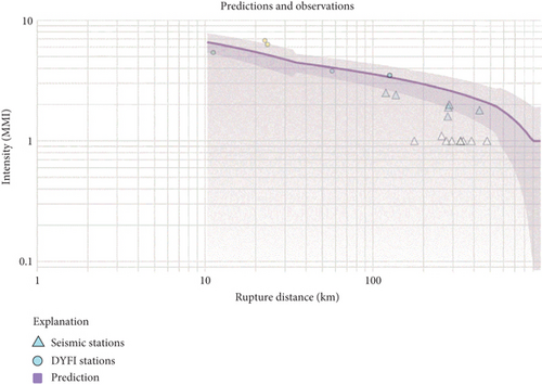
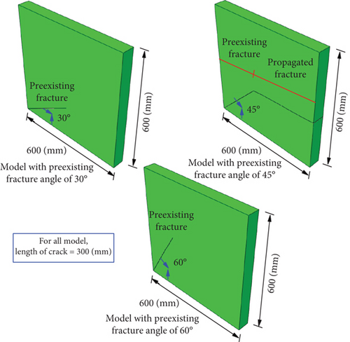
Figure 4 depicts the three models for the numerical simulation. It is assumed that the bottom of the model is rigid, and the seismic acceleration is applied to the model in the vertical direction. According to the boundary condition, the model is subjected to the nonlinear tensile loading in both positive and negative directions. The preexisting fracture’s angle of 30°, 45°, and 60° was simulated in three models. The length for all preexisting fractures is 300 mm. A point of analysis was selected for measuring the nonlinear displacement of the model during the model facing the propagation of the preexisting fracture and leading to the failure of the model.
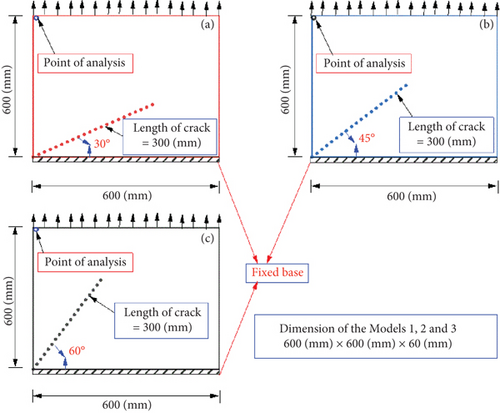
The crack propagation of rock-like material due to seismic loading has been simulated. For simplification, axial nonlinear loading was applied vertically to the model to simulate crack propagation [45]. Figure 5 used the same method of applying seismic loading. The boundary condition used in this study is presented in Figure 4.
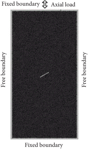
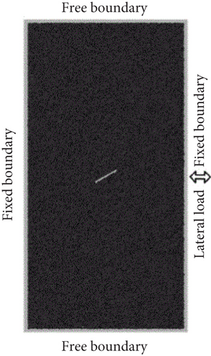
The boundary condition of this study was previously verified according to the literature report [45].
During the transfer of seismic waves, the transmission and reflection phenomenon occurs at the interface [46]. However, due to the model’s small size, the reflection and transmission phenomena are usually unrecognizable in the numerical model [45]. As part of a recent 2022-based study, the seismic loading was applied to the specimen with 76 × 152 mm dimensions, and the transmission and reflection phenomenon did not occur [45].
Another experimental study reported appropriate results for crack propagation simulation of the specimen gypsum with 76 × 152 mm dimensions [47]. The numerical approach was carried out for crack propagation of rock-like material with 76 × 152 mm dimensions, and the same numerical simulation results were observed in laboratory experiments [48]. In addition, for the simulation of crack propagation on rock-like material, the experimental investigation has been done by designing a specimen of 635 × 279 × 203 mm dimensions [49]. In the current study, with the transfer of seismic waves, the transmission and reflection phenomenon, and acceptable results from the previous research, the specimen with the size of 600 ×600 ×60 mm dimensions has been designed for the simulation of the crack propagation. The model contains preexisting cracks, and the seismic loading was applied based on the seismic data from the Florina earthquake mentioned previously.
2.1. ANN
ANN establishes a nonlinear connection from the input to the output of a system without acknowledging the statistically simulated model. By using algorithms to train, test, and validate the data, ANN produces appropriate predictions concerning input with acceptable generalization and quality.
The backpropagation (BP) algorithm is the keystone of the neural network training process. The algorithm improves prediction by minimizing error by applying the forward and backward phases. The forward pass provides propagation and transformation of the input at all ANN layers individually, and the backward pass improves the connection of weights and bias [50]. An accurately designed ANN produces a precise input–output. Overfitting data is a potential problem in ANN. Overfitting is an occurrence in ANN that memorizes the training phase data alone. An ANN subjected to overfitting training cannot represent the actual relationship between the inputs and outputs [51, 52]. The training and validation errors are compared to avoid overfitting, and the training error must not be smaller than the validation error. The training phase needs to stop at an appropriate point [53]. BP performs highly in ANN and can develop nonlinear mapping with associated nonlinear relationships between inputs and outputs [54]. It has been seen that ANN presents acceptable precision in the calculation of crack openings [55]. Selecting a single hidden layer for ANN architectural design leads to acceptable results [56]. The present study selects a single hidden layer for ANN architectural design.
Because of the high experimental laboratory requirements budget and to minimize the time in making engineering decisions, ANN is used in many geotechnical engineering [36, 37]. In addition, recent studies show that advanced mathematical methods applied in ANN and statistical methods result in appropriate prediction and also support the integrated results of the experiment with more accuracy compared to the old method [36–41].
In Equations (1) and (2), nin presented the quantity of required input for nodes of the network, nhid stands for the number of designed hidden nodes, wij refers to the weight of joining the ith input node to the jth hidden node, bj refers to the bias of the network for the jth hidden node, xi stands for the ith feature of the input vector, nin will be the output of the ith input node, and g presented for the activation function of the hidden nodes. nout is presented for the number of nodes at the output layer, wjk refers to the weight linking the jth hidden node and the kth output node, bk stands for the bias of the kth output node, and f refers to the transfer function of the kth output node [57].
In this study, the Levenberg–Marquardt algorithms, the training, validation, and test data have been applied by using the Abalone Data Analysis set.
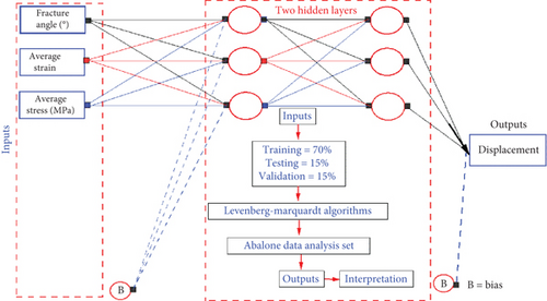
The ANN has been used to predict a connection between crack propagation magnitudes and characteristics of the cyclic load [60]. In the lack of crack propagation, the impact of the preexisting crack angle on the displacement mechanism of the model must be investigated using ANN. ANN is a nondestructive testing procedure that supports engineering decision-making, seismic design reliability evaluation, and trustworthiness management performance. Figure 6 shows a flow chart and simplified ANN design.
2.2. XFEM
In the present work, the initial preexisting crack is one of the main parameters for using XFEM.
3. Results and Discussion
According to Figure 7, when applying the same magnitude of seismic acceleration and boundary condition, the angle of the preexisting crack is responsible for the propagation crack. The interface strength of the crack was associated with the angle of the propagation crack. The loading and unloading stiffness of the model was changed in association with the crack’s angle on the crack propagation process. According to the numerical simulation results, the model with the preexisting fracture angle of 45° contained the preexisting fracture and propagated fracture sections.
The crack on the model propagates during the changing direction of the seismic loading [45], and the simulated model’s loading and unloading minimize the material’s strength and stiffness and lead to the model’s failure.
Figure 8 shows the displacement applied to the selected point. Figure 4 highlights the selected point for analyzing the displacement in the vertical direction. Based on the boundary condition, the main applied load on the model is seismic loading in the vertical direction. The vertical displacement is depicted in Figures 8 and 9 for the models with the preexisting fracture angles of 30°, 45°, and 60°. The model with a preexisting fracture angle of 45° has a different displacement mechanism than the model with the preexisting fracture angles of 30° and 60°. The propagation of the crack causes a change in the displacement mechanism.
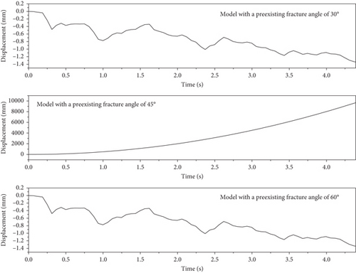
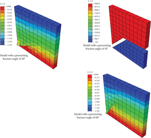
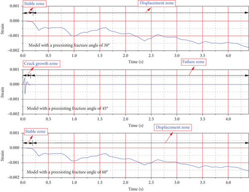
Figure 9 illustrates the displacement and failure mechanisms of the models. The models with the preexisting fracture angles of 30° and 60° are subjected to punching in the lower part of the preexisting fracture. During the final stage of the numerical simulation, two parts of the model, with the preexisting fracture angles of 45°, have been separated, which impacts recording placement. Concerning Figures 10 and 11, by considering stress and strain diagrams, it is observed that the crack propagation of the model with preexisting fracture angles of 45° has been completed in time before 0.14 s. In comparison, the models with the preexisting fracture angles of 30° and 60° have resistance against crack propagation until the applied acceleration loading ends.
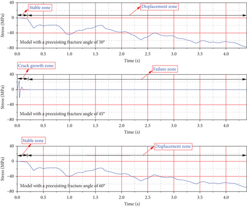
Crack propagation was associated with the stress developing in the model. The model with a preexisting fracture angle of 45° faces a different mechanism of stress fluctuation compared to the model with preexisting fracture angles of 30° and 60°. During crack propagation, the stress exhibits high and low levels. When the model is not subjected to crack propagation, the stress causes displacement in the negative direction. The stress associated with the crack propagation controls the displacement produced in the model.
The seismic loading acts on the rock in multiple directions, developing tension and shear loading. The crack propagation results from seismic loading, rock fracture mechanics, and seismic energy studied [65, 66]. The XFEM outcome was validated using the scale test results [67]. In this study, the XFEM-simulated sandstone fracture agrees well with that available in the literature [45].
Concerning Figures 10 and 11, after applying seismic acceleration to the model, a multidimensional failure configuration model has been depicted. The seismic response process, including the model with preexisting fracture angles of 30° and 60°, exhibits a stable zone and displacement zone, while the model with a preexisting fracture angle of 45° has a crack growth zone and failure zone. Changing preexisting fracture angles leads to modification of the model seismic response. There is a direct relationship between the fracture’s seismic toughness and the shape of the preexisting crack. Preexisting fracture angle morphology changes the seismic response of the model from a developing displacement to crack growth.
Based on the fracture mechanics prediction, it has been observed that the level of fracture seismic toughness and preexisting fracture angle morphology of the model is responsible for the developing, stable zone, displacement zone, crack growth zone, and failure zone of the model. The preexisting crack of the rock model changes the stiffness of the rock through the fracture’s seismic toughness. In addition, the shape of the preexisting fracture angle controls the external nonlinear loading applied to the model.
According to Figure 12, regression analysis for displacement prediction, the regression formula is presented based on the relationship between the target and outcome. Four different regression formulas exist for training, testing validation, and overall. For the relationship between output and target, refer to Figure 12 on the x-axis and y-axis.
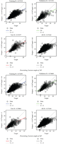
Tables 2 and 3 illustrate the data used in ANN. To integrate the displacement prediction, ANN has been applied to the models with preexisting fracture angles of 30° and 60° that do not face propagation. Table 4 presents the coefficient of determination (R2) and mean squared error (MSE).
| No. | Fracture angle (°) | Average strain | Average stress (MPa) | Average displacement (mm) |
|---|---|---|---|---|
| 1 | 30 | −1.46627e − 5 | 0.60127 | 0.00524 |
| 2 | 30 | −2.17066e − 4 | −1.82821 | −0.03561 |
| 3 | 30 | −4.85433e − 4 | −27.26469 | −0.44882 |
| 4 | 30 | −4.77652e − 4 | −19.50649 | −0.35018 |
| 5 | 30 | −4.43228e − 4 | −19.18037 | −0.33195 |
| 6 | 30 | −5.51786e − 4 | −19.86613 | −0.35548 |
| 7 | 30 | −0.001 | −38.1682 | −0.68537 |
| 8 | 30 | −8.39e − 4 | −41.10773 | −0.70624 |
| 9 | 30 | −7.52002e − 4 | −33.06416 | −0.5754 |
| 10 | 30 | −6.35313e − 4 | −28.03959 | −0.48665 |
| 11 | 30 | −4.67755e − 4 | −22.59276 | −0.39251 |
| 12 | 30 | −6.5899e − 4 | −24.26267 | −0.41837 |
| 13 | 30 | −7.95721e − 4 | −32.21675 | −0.55821 |
| 14 | 30 | −8.68582e − 4 | −37.52411 | −0.6519 |
| 15 | 30 | −9.4283e − 4 | −38.05542 | −0.65614 |
| 16 | 30 | −0.0012 | −47.71801 | −0.81399 |
| 17 | 30 | −0.00121 | −55.18875 | −0.97479 |
| 18 | 30 | −9.69834e − 4 | −44.99559 | −0.80297 |
| 19 | 30 | −0.00105 | −43.2751 | −0.73785 |
| 20 | 30 | −0.0011 | −47.76748 | −0.828 |
| 21 | 30 | −0.00118 | −48.82255 | −0.83533 |
| 22 | 30 | −0.00128 | −55.16225 | −0.95665 |
| 23 | 30 | −0.00142 | −60.09551 | −1.03435 |
| 24 | 30 | −0.00147 | −65.74971 | −1.16203 |
| 25 | 30 | −0.00144 | −61.51245 | −1.05199 |
| 26 | 30 | −0.00149 | −64.04928 | −1.12105 |
| 27 | 30 | −0.00148 | −65.02705 | −1.15059 |
| 28 | 30 | −0.00149 | −64.33574 | −1.1022 |
| 29 | 30 | −0.00158 | −67.48391 | −1.14975 |
| 30 | 30 | −0.00179 | −76.67403 | −1.29864 |
| No. | Fracture angle (°) | Average strain | Average stress (MPa) | Average displacement (mm) |
|---|---|---|---|---|
| 1 | 60 | −1.2579e − 6 | 0 | 0.01045 |
| 2 | 60 | −9.94953e − 5 | −1.44689 | −0.0319 |
| 3 | 60 | −4.66846e − 4 | −22.03171 | −0.4721 |
| 4 | 60 | −4.25406e − 4 | −16.7743 | −0.34048 |
| 5 | 60 | −3.81802e − 4 | −17.23474 | −0.33313 |
| 6 | 60 | −4.41857e − 4 | −16.98832 | −0.34829 |
| 7 | 60 | −8.53586e − 4 | −32.06744 | −0.67297 |
| 8 | 60 | −7.58396e − 4 | −37.33546 | −0.70911 |
| 9 | 60 | −6.65477e − 4 | −29.43286 | −0.57548 |
| 10 | 60 | −5.50742e − 4 | −25.28501 | −0.48562 |
| 11 | 60 | −4.19424e − 4 | −20.6971 | −0.38831 |
| 12 | 60 | −5.58429e − 4 | −20.37453 | −0.43495 |
| 13 | 60 | −6.73008e − 4 | −28.47592 | −0.56483 |
| 14 | 60 | −7.5033e − 4 | −33.48684 | −0.6528 |
| 15 | 60 | −7.94566e − 4 | −33.59655 | −0.66737 |
| 16 | 60 | −0.00101 | −41.80149 | −0.84395 |
| 17 | 60 | −0.00105 | −50.01415 | −0.94668 |
| 18 | 60 | −8.52342e − 4 | −40.97703 | −0.76799 |
| 19 | 60 | −8.93517e − 4 | −38.22011 | −0.76216 |
| 20 | 60 | −9.52801e − 4 | −42.61824 | −0.83185 |
| 21 | 60 | −0.00101 | −43.15088 | −0.86362 |
| 22 | 60 | −0.0011 | −49.24388 | −0.96018 |
| 23 | 60 | −0.00122 | −53.52478 | −1.05297 |
| 24 | 60 | −0.00128 | −59.17075 | −1.12694 |
| 25 | 60 | −0.00124 | −54.74662 | −1.07824 |
| 26 | 60 | −0.00129 | −57.18973 | −1.11867 |
| 27 | 60 | −0.00128 | −58.2887 | −1.12042 |
| 28 | 60 | −0.00129 | −57.3529 | −1.12421 |
| 29 | 60 | −0.00137 | −60.05804 | −1.18921 |
| 30 | 60 | −0.00155 | −68.30408 | −1.34861 |
| — | Training | Validation | Test | Number of layers in ANNs | |
|---|---|---|---|---|---|
| Preexisting fracture angles of 30° | R2 | 0.7372 | 0.7174 | 0.7238 | 1 |
| RMSE | 4.8610 | 4.9945 | 4.5595 | 1 | |
| Preexisting fracture angles of 60° | R2 | 0.7330 | 0.7467 | 0.7086 | 1 |
| RMSE | 4.7105 | 4.8422 | 5.3731 | 1 |
Regarding the literature, the present study designed the ANN with two hidden layers [56]. The input parameters for ANN are average strain and stress in the critical selected point of the model and the preexisting fracture angles of the model. After the data generation by Abalone Data Analysis was applied in the Levenberg–Marquardt algorithms, the training, validation, and test data were 2923, 627, and 627, respectively.
The ANN was designed to treat displacement prediction as a main regression problem. Figure 12 presents regression analysis for displacement prediction in the models with preexisting fracture angles of 30° and 60°. It is essential to observe that the regression analysis is designed for displacement prediction assessment. Multiple variables were considered instead of a single variable.
The target and output are concurrent variables of the prediction model and share correlation information across targets considered for displacement prediction [68]. In the current study, Abalone Data Analysis generated sufficient data to predict displacement without changing the main characteristics of the data.
Figure 13 shows the histograms for displacement prediction in the models with preexisting fracture angles of 30° and 60°. Each input variable directly impacts the output when using a histogram. Based on the displacement prediction by the histograms, the preexisting fracture angles directly impact the model’s vibration mechanism and failure pattern.
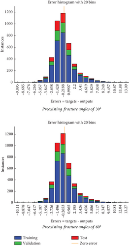
Table 4 illustrates R2 and root mean squared error (RMSE) obtained to evaluate prediction accuracy. In ANN related to validation, training, and testing data, the overfitting problem was not observed.
In ANN architectural design, 70% of training data, 15% of testing data, and 15% of validation data were selected. To minimize error in the transformation of the input at all ANN layers, the appropriate ANN architectural design plays a key function. To avoid overfitting data, producing low-quality training data, and pressurizing on validation and test data, ANN architectural design needs to be allocated properly. Due to the huge data in the present study, none of the motioned problems have occurred. Figure 14 shows the cost function variations chart that has been represented for each model concerning the training, validation, and test data. The best validation performance of the prediction accuracy of displacement for models containing preexisting fracture angles of 30° and 60° is illustrated.

3.1. Validation of Simulation and Prediction
Crack propagation initiates if tensile displacement occurs due to the seismic loading applied to the sandstone [45]. In the models with the preexisting fracture angles of 30° and 60°, compressive displacement was observed. Meanwhile, in the model with the preexisting fracture angles of 45°, the tensile displacement has occurred. The effectiveness of the proposed model is validated by comparing it with those reported in the literature.
Figures 15 and 16 describe the wave–crack interactions in the experimental and numerical simulation considering the location of the crack appearance, strain energy magnitude, material’s rock, and displacement mechanism [69]. Based on the crack angle, the crack propagation exhibits differently. The resultant strain energy causes crack propagation or compressive displacement and tensile displacement to the model.
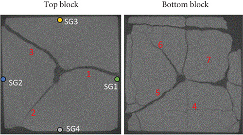
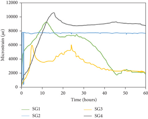
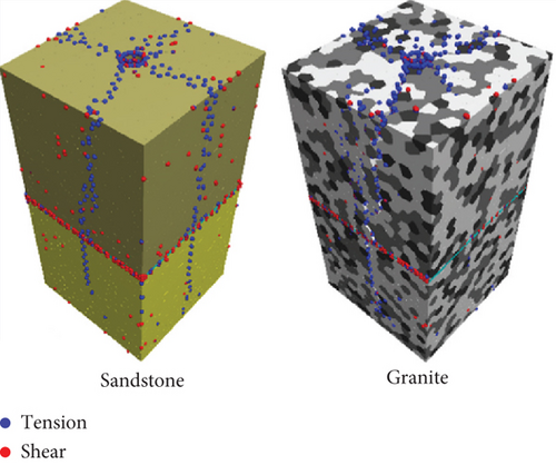
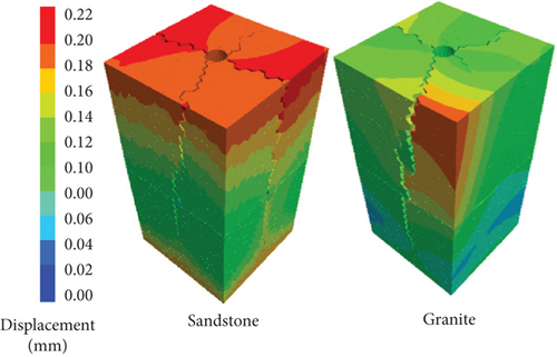
Repeating axial seismic loading causes crack propagation. Due to the change in direction of the seismic loading from axial to lateral, the preexisting fracture angle leads to propagation [45]. When the model contains a preexisting crack with 45°, the seismic loading changes direction, and the fracture seismic toughness model reaches the minimum level. Due to these reasons and based on the boundary conditions of the simulated model, the model with preexisting fracture angles of 30° and 60° has not been subjected to crack propagation.
The model seismic response mode classification is made. To validate the crack simulation mechanism, the seismic response of the model is classified into the stable zone, displacement zone, crack growth zone, and failure zone in association with the preexisting crack angle model.
In the displacement zone, the seismic loading is applied in a single direction, while in the crack growth zone, the seismic loading changes direction from axial to lateral.
4. Conclusion
- -
In equal seismic acceleration, the angle of the preexisting crack is responsible for the propagation of the crack, displacement magnitude, and failure mechanism of the model.
- -
A propagation crack occurs when the preexisting crack of the model is 45°. The models with 30 and 60° preexisting cracks exhibit higher interface strength and higher seismic stability.
- -
According to the boundary condition of the simulated model, the direction of the applied seismic load was constant, and the preexisting fracture angle is an essential function in the crack propagation.
- -
The stiffness and strength of the model are related to preexisting cracks, which have developed in the structure due to previous earthquakes.
- -
The direction of the crack growth zone within the simulated specimen has been identified. The seismic response of the model is divided into the model’s stable zone, displacement zone, crack growth zone, and failure zone. There is a direct relationship between the fracture’s seismic toughness and the shape of the preexisting crack. The preexisting crack of the rock changes the stiffness of the rock through the fracture’s seismic toughness. The higher fracture seismic toughness leads to minimized crack propagation of the model. In addition, the tensile displacement is responsible for creating a crack growth zone. The approach of the study lies in the application of the ANN to analyze the multifaceted displacement mechanism performance of the model under seismic acceleration.
- -
There are many cracks in the several structures. The paper’s outcome helps to understand which type of crack is more critical for the seismic stability of the structure. Based on the propagation of the crack, the failure of the structure and displacement can be predicted.
- -
The present simulation significantly supports the prediction failure mechanism of the model with the changing angle of the preexisting crack.
- -
In future research work, the types of cracks, the geometry of the preexisting crack, initial and dynamic boundary conditions, material characteristics, nature of loading, simulation method, and adaptation of the theoretical concept in the numerical simulation could be parameters for investigation.
Conflicts of Interest
The authors declare no conflicts of interest.
Funding
This study was funded by the Abu Dhabi University, Abu Dhabi, UAE, as a part of an internal project.
Open Research
Data Availability Statement
Data are contained within this manuscript. Enquiries about data availability should be directed to the authors.


