Influence of Interference Fit on Dynamic Characteristics of TBM Cutter Bearing
Abstract
Bearing interference fits have a significant effect on the cutting characteristics of TBM cutters. In this paper, first, the base interference fit was calculated to select a reasonable tolerance fit. A TBM cutter bearing dynamics model was established by considering the influencing factors, such as bearing interference fit and thermal displacement. Second, the variations in the thermal displacement and stiffness with increasing load were analyzed. Last, the simulation was analyzed via the phase trajectory and Poincaré methods. Time–frequency domain analysis was used to explore the optimum value of the bearing interference fit. The results show that the bearing stiffness tends to increase nonlinearly with the amount of interference fit. In addition, temperature has a significant effect on the thermal displacement of bearings. When the load increased from 2000 to 8000 N, the change in interference caused by thermal displacement increased from 4.45 to 8.61 μm. The maximum error between experiment and simulation is 7.08%, which verifies the reliability of the model. The investigation of the TBM cutter bearing interference fit facilitates analysis of the vibration characteristics of the cutter during the heavy-duty cutting process.
1. Introduction
Tunnel boring machine (TBM) for full-section rock has excellent advantages in underground space and tunnel construction [1–3]. To ensure the cutting quality of the cutter system, interference fits are utilized between the cutter shaft and the tapered roller bearings. During the process of rock cutting by the cutter, the friction between the rollers and raceways generates much heat, resulting in thermal deformation of the bearings. As a result of thermal deformation, the bearing radial displacement changes, which results in changes in bearing interference and clearance. Reducing the interference fit will alter the cutter bearing fit. If the interference fit is too small, it can result in increased friction between the shaft and bearing, which can damage the bearing and the cutter shaft [4, 5]. Therefore, analyzing the practical engineering significance of the cutter bearing interference fit on the cutting characteristics of the cutter is beneficial.
In a full-section TBM cutter system, interference between the cutter shaft and bearings is used. To date, more researchers have investigated the effect of interference fits on the vibration characteristics of bearings. Wang et al. [6] investigated how the bearing vibration is affected by the change in bearing inner ring interference under various working conditions. The results show that an appropriate increase in the interference between the bearing and the shaft under high-speed conditions facilitates analysis of the dynamic characteristics of the bearing. Liu et al. [7] proposed an uncertain ball bearing–rotor dynamics model based on the Chebyshev interval method. The results indicated that a reasonable design of the interference can reduce the displacement dispersion and time-varying stiffness. Gao et al. [8] discussed the effects of preload and interference fit values on the dynamic characteristics of FCBBs. The interference fit value affects the internal clearance, and an increase in the internal clearance reduces the radial stiffness of the bearing. Gruescu et al. [9] validated the analytical relationship between pressure and bearing capacity under simple loads via FEM simulations. The results show that the pressure vector combination is invalid. However, the literature above only examined the impact of fit on system vibration and did not consider other factors, such as temperature, that affect the variation in interference fit.
The interference fit is also affected by other factors, such as temperature. Several researchers have performed research in bearing experiments with respect to temperature. Shi et al. [10] analyzed the effect on the correlation fit at different operating temperatures and speeds. The results revealed that the outer ring vibration increased with increasing temperature. Bai et al. [11] considered a temperature-dependent dynamic model for fit clearance and investigated the trend of variation in peak frequency with temperature. When the temperature increases, the rotational speed of the outer ring subsequently increases, and the identification of the defective frequency of the bearing becomes more pronounced. Liu et al. [12] developed a thermal error model for a spindle. The experimental validation shows that the model provides a high degree of accuracy. Dai et al. [13] constructed a differential evolution–gray wolf optimization–support vector regression (DE-GWO-SVR) thermal error prediction model. The model is used to predict the thermal error of the electrical spindle under different preloading forces. The accuracy of the thermal error prediction model is greater than 95%, and the error is less than 2 μm. Sun et al. [14] established a new transient temperature analysis model for damaged bearings by considering the thermosolid coupling in the bearing structure. The results show that the transient temperature analysis model can analyze the temperature changes in damaged bearings more accurately. Lee et al. [15] analyzed the temperature distribution, temperature rise, and thermal displacement of a spindle system at various rotational speeds via finite element and thermal displacement analysis methods. Xu et al. [16] proposed a model of a flexible rotor system that considers the unbalanced mass by taking into account time-varying bearing force to analyze the effect of the unbalanced mass on the vibration characteristics of the rotor system, which provides a new reference and research method for the vibration study of rotor systems that consider the unbalanced mass. Li et al. [17] proposed an improved method for calculating the stiffness of spline couplings considering the deflection of the inner spline fillet base and established a dynamic model of the floating spline coupling shaft system with parallel misalignment and a tooth gap. The accuracy of the proposed dynamic model of the floating spline coupling shaft system is verified via experiments. Liu et al. [18] developed a comprehensive dynamic model of a flexible propeller shaft combined housing system, which considers the time-varying stiffness of the bearings and the contact force. A combined numerical and semianalytical solution strategy approach is used to increase the computational efficiency and reasonable accuracy of previous methods. On the basis of the above literature, researchers worldwide have conducted more research on bearing fit. However, considering the effect of interference variation caused by thermal displacement and dynamic displacement on bearing vibration characteristics under heavy load conditions, this research is insufficient. In this work, the variation in interference caused by the thermal and dynamic displacement of bearings is analyzed under heavy load conditions. The variable interference is compensated and substituted into the bearing dynamic model to seek the optimal value of the bearing interference under heavy load conditions.
Most studies focus on high-speed or simple load conditions. There is a lack of research on the bearing temperature distribution and thermal displacement resulting in bearing fit failure under heavy loads and in extreme environments. In this paper, the interference fit in the cutter system is considered to research the changes in the dynamic characteristics of the bearings so that the model is more closely related to the actual conditions. The variation is analyzed in interference caused by low speed and heavy loads, the temperature field, and complex environmental factors, and the dynamic characteristics of cutter bearings with different interference amounts are also investigated.
2. Interference Fit Model of the TBM Cutter Bearing
In a TBM cutter system, an interference fit is usually used between the cutter shaft and the bearing. The value of the interference fit between the shaft and the bearing directly affects the deformation of the raceway in the bearing. The deformation of the bearing inevitably results in deformation of the inner raceway of the bearing, which affects the structural parameters of the bearing [19].
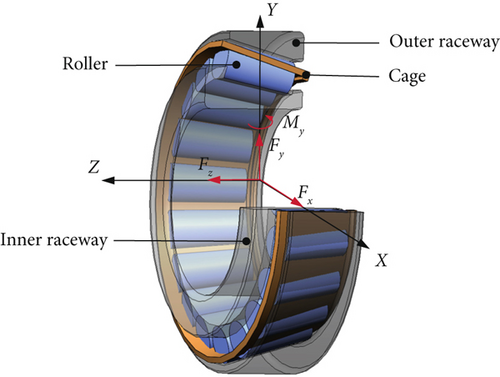
Tapered roller bearings are commonly used in applications in which they need to withstand both radial and axial loads. The bearing of the inner and outer rings is relatively simple. The motion of the roller is relatively complex, and sliding friction and rolling friction exist with the raceway. According to the law of bearing motion, the coordinate system of bearing motion is established as shown in Figure 1.
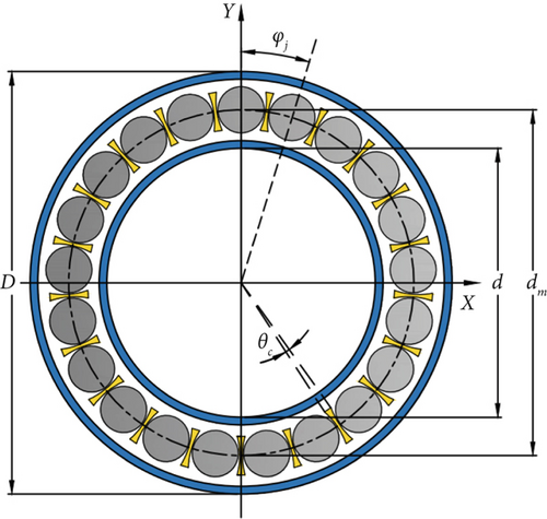
A schematic of the geometric structure of the bearing is shown in Figure 2, and its geometric parameters are presented in Table 1.
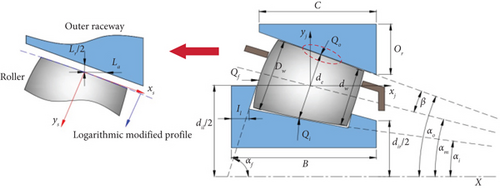
| Parameter | Value | Units |
|---|---|---|
| Inner ring width B | 17 | mm |
| Outer ring width C | 13 | mm |
| Outer ring diameter D | 55 | mm |
| Inner diameter d | 30 | mm |
| Pitch diameter dm | 42.5 | mm |
| Contact angle αm | 13.5 | ° |
| Half-cone angle β | 2.5 | ° |
| Roller length L | 12.09 | mm |
| Diameter of the large end of the roller Dw | 6.24 | mm |
| Diameter of the small end of the roller dw | 5.44 | mm |
2.1. Calculation of the Bearing Interference Amount
According to Equations (2)–(6), the basic interference required for the cutter bearing is 0.025 mm. In accordance with the ISO 286 standard, the interference fit grade between the inner ring of the bearing and the shaft under heavy load conditions is selected as H7/p6. The installation dimensions of the shaft are , and the inner ring size of the bearing is . The interference range from the inner ring of the bearing to the cutter shaft is between 0.001 and 0.035 mm. The adopted values do not exceed the theoretical maximum value and are within a reasonable range.
2.2. Effects of Thermal Deformation on Interference Fits
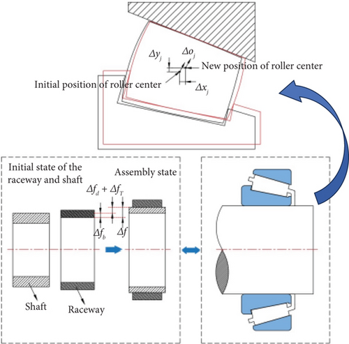
Tapered roller bearings generate considerable heat while operating under heavy loads. The heat generated increases the temperature of the system. Thermal displacement results in changes in the fit between the shaft and the bearing [20].
When the dynamic equation of the bearing is established, some assumptions are needed. First, the rolling between the rolling body and the inner and outer raceways is assumed to be pure rolling. Second, the moment of inertia of each component inside the bearing is disregarded. Last, the effects of the ripple, lubrication, oil film, and cage on the roller are disregarded. There is no mutual interference between the rolling body and the cage in motion.
- 1.
The bearing material is assumed to be homogeneous and isotropic; that is, its thermophysical properties remain consistent in different directions and positions.
- 2.
The coefficient of thermal expansion is assumed to be constant, and the material’s plastic deformation is disregarded.
- 3.
In the process of cutter assembly, to ensure the effective operation of the bearing, a fixed pretension is applied in the axial direction. Two identical bearings are simultaneously installed back-to-back, and the inner ring and the shaft have the same axial thermal displacement, so the axial thermal displacement is disregarded.
2.3. Dynamic Model of the Tapered Roller Bearing
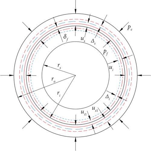
3. Results and Analysis
3.1. Analyses of the Bearing Stiffness
The parameters of the bearing dimensions and material properties are substituted into Equations (14) and (15). By calculating the gradual increase from 2000 to 8000 N (500 N interval), the stiffness change of the roller with the inner raceway and outer raceway can be obtained for different loads, and the results are shown in Figure 5.
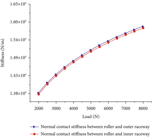
Figure 5 shows that the change in stiffness increases nonlinearly with increasing load. At 2000 N, the stiffnesses between the roller and the inner raceway and between the roller and the outer raceway are 1.372 × 10⁹ and 1.375 × 10⁹ N/m, respectively. At 8000 N, the stiffness is divided into 1.576 × 10⁹ and 1.581 × 10⁹ N/m, whereas the stiffness increases by 12.94% and 13.03%, respectively. When the load on the bearing increases, the contact between the bearing rollers and the ring raceways becomes closer. The reduction in the bearing clearance causes a significant increase in the bearing stiffness. The increase in load causes a change in the stiffness mechanism of the bearing.
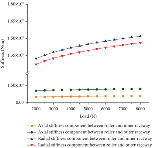
According to Equation (16), the radial stiffness components and axial stiffness components between the roller and the inner and outer raceways can be obtained for different loads, and the results are shown in Figure 6. Figure 6 shows that the stiffness increases nonlinearly with increasing load. The radial stiffness component of the bearing is significantly greater than the axial stiffness component, and the change in the radial stiffness component is more obvious. When the load is increased from 2000 to 8000 N, the axial stiffness between the roller and the outer raceway increases from 1.045 × 10⁸ to 1.201 × 10⁸ N/m, an increase of 12.99%, and the radial stiffness increases from 1.271 × 10⁹ to 1.461 × 10⁹ N/m, an increase of 13.00%. The main reason that the radial stiffness of bearings is greater than the axial stiffness is their structural design and load transfer characteristics. Under radial loading, the rolling body and the raceway form a large area of normal contact, and the stress distribution is uniform, which increases the radial support. However, the axial load tends to contact only through the edge of the rolling body or a small area, and the contact area is small, resulting in local stress concentration. Together, these factors make the radial stiffness significantly greater than the axial stiffness.
In the analysis of stiffness variations, interference fits and load variations are considered. According to Hertz contact theory, the stiffness can be derived for different amounts of interference and different loads, and the results are shown in Figure 7. The stiffness increases nonlinearly as the amount of interference fit increases. An increase in the interference fit decreases the bearing clearance, which increases the bearing stiffness. At the 2000 N load, the bearing interference fit increases from 5 to 20 μm, and the stiffness increases from 4.32 × 10⁸ to 2.02 × 10⁹ N/m. The bearing interference fit has a more pronounced effect on the bearing stiffness under the same load. The interference fit combines the bearing inner ring and the shaft tightly to form a more rigid overall structure. With increasing interference, the load transfer path between the rollers and the raceway becomes shorter and more efficient. The local stress concentration causes the clearance to be reduced so that more rollers are loaded, and finally, the stiffness is improved.
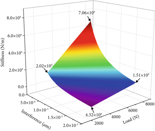
In summary, the bearing stiffness increases significantly as the load and interference fit increase. The load and interference fit have a significant effect on the bearing stiffness. Changes in the bearing stiffness affect the bearing vibration simultaneously. Too much or too little bearing stiffness has a negative effect on the bearing vibration.
3.2. Analyses of the Bearing Thermal Displacement
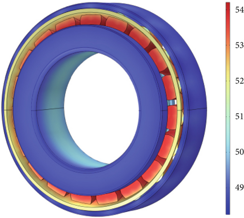
Through finite element simulation software, the bearing temperature field of the TBM cutter is obtained. Figure 8 shows that the temperature of the rollers is higher than that of the rollers in the other parts. The contact force and friction between the roller and the raceway increase as the load increases during the rock-cutting process of the TBM cutter.
The increase in bearing temperature with time can be observed in Figure 9. The bearing temperature increases nonlinearly with time. The temperature increases sharply before 20 min and gradually levels off by 24 min, eventually reaching a steady state.
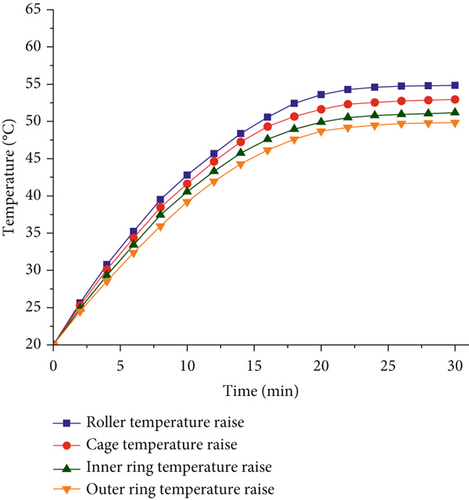
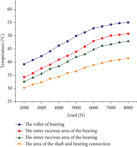
Figure 10 shows the temperature variation of the roller and the inner and outer raceways for different loads. The temperature increases nonlinearly as the load increases. The bearing roller temperature can reach 55.03°C at a load of 8000 N. Compared with that at the 2000 N load, the temperature at the 8000 N load is increased by 15.87°C. The main reason for the increased load is the increased contact force between the rollers and the inner and outer raceways, which results in greater friction.
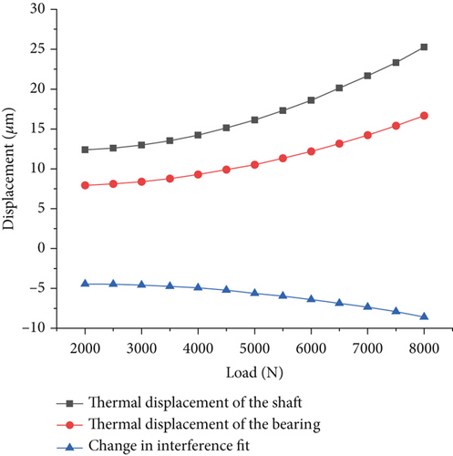
Combined with the temperature field distribution cloud diagram of the TBM cutter bearing, according to Equations (7) and (8), the thermal displacement of the bearing inner ring and shaft and the change in fit quantity are calculated, as shown in Figure 11. The thermal displacement variation trends of the inner ring of the bearing and the shaft are basically similar, showing a nonlinear increasing characteristic with increasing load. When the load increased from 2000 to 8000 N, the thermal displacement of the shaft increased by 12.88 μm, and the thermal displacement of the inner ring of the bearing increased by 8.73 μm. Because the thermal displacement of the shaft is always greater than that of the inner ring of the bearing with increasing load, the fit between the inner ring of the bearing and the shaft becomes tighter. With increasing load, the variation in fit tends to increase. When the load increased from 2000 to 8000 N, the change in fit caused by the increase in temperature increased from 4.45 to 8.61 μm.
3.3. Analyses of the Bearing Stability
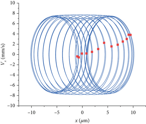
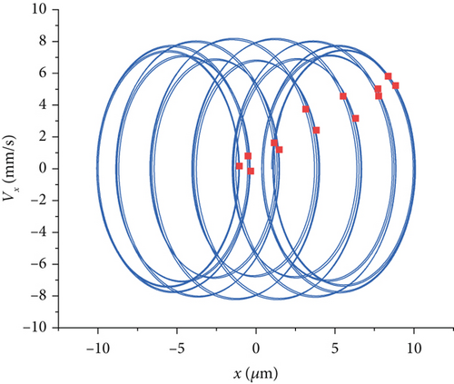
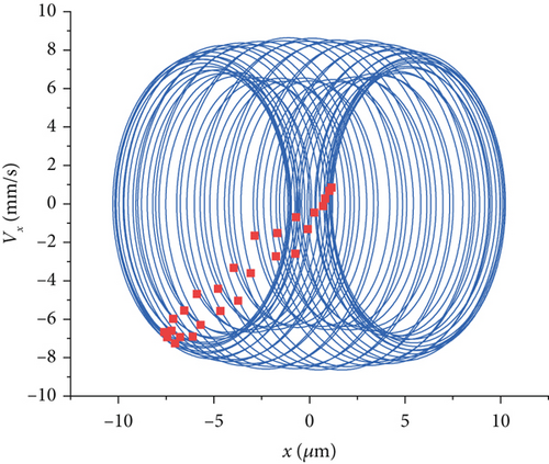
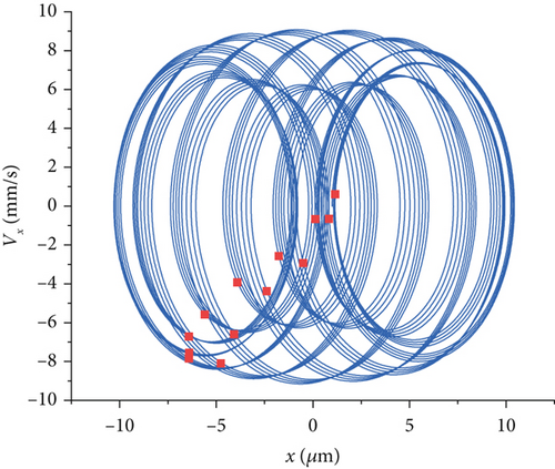
Different speeds have different effects on the bearing vibration. Figure 12 shows a comparison of the phase trajectories and the Poincaré sections at four rotational speeds. At 10 rpm, the phase trajectory is symmetrically elliptical. The appearance of 13 periodic attractors in the Poincaré sections indicates that the system is in periodic motion at this point. At 20 rpm, the phase trajectory does not change much compared with that at 10 rpm. At 30 rpm, the phase trajectory is superimposed by many circles. The phase trajectory diagram becomes rather chaotic, and the periodic changes are not obvious. Compared with Figure 12a,b, the Poincaré section has more attractors and a more complex form, indicating that under this rotational speed condition, the motion state of the system changes, and the system stability is poor. The results indicate that at a rotational speed of 30 rpm, the motion performance of the bearing system is poor, and the system enters a chaotic state. At 40 rpm, the phase trajectory consists of four cycles per cycle and is “∞” shaped. The Poincaré section reverts to 13 periodic attractors, and the system returns to periodic motion. The above results show that the roll cutter is not used for rock crushing at 30 rpm. The above results show that 30 rpm is not favorable for the cutter bearings and provides the cutter cutting speed for subsequent experiments.
3.4. Analyses of the Bearing Time and Frequency Domain
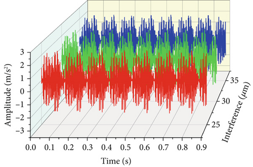
When the radial load is 5000 N, according to the change results of the bearing interference and considering the coupling factors and the uncertainty in actual engineering, the optimal value of the bearing interference should be in the range of 25~35 μm. The bearing vibration signals under different interference amounts of 25, 30, and 35 μm are compared and analyzed.
Figure 13 shows the time–frequency diagram of the bearing vibration with different interference amounts under a 5000 N load. The time domain diagram shows that the bearing vibration is regular and changes periodically. When the bearing interference is 25, 30, and 35 μm, the peak accelerations are 2.69, 2.46, and 2.58 m/s2, respectively. With increasing interference fit value, the vibration first tends to decrease but then tends to increase, and the vibration period tends to decrease.
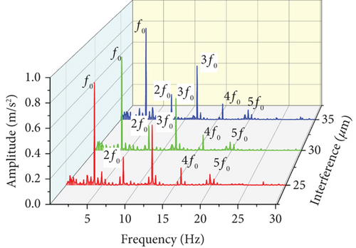
As shown in Figure 13b, the vibration frequency domain graphs of the bearings under the three interference amounts present fifth-order characteristic frequencies. Because the bearing works under heavy load conditions, the load distribution inside the bearing is uneven, and the friction force and contact force between the roller and the inner raceway fluctuate violently, which manifests as a doubling frequency. The harmonic interference at double frequency is mostly under a heavy load. The emergence of the triple frequency is mostly the problem of bearing matching. A bearing that is too tight or too loose will cause bearing vibration in the process of operation. The amplitudes at the triple frequency are 0.494, 0.452, and 0.497 m/s2. Weak misalignment and centroid deviation of the bearing system are the main causes of the four- and fivefold frequencies. The vibration amplitude of the bearing under three different interference amounts shows an obvious peak change at the triple frequency. The amplitude decreases first and then increases with increasing bearing interference. Considering the variation factors of interference caused by thermal displacement and dynamic displacement, under the 5000 N heavy load condition, when the bearing interference is 30 μm, the bearing vibration is small, and the operation is more stable.
4. Experimental Verification
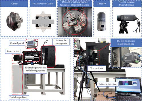
The dynamic characteristics of the cutter bearings are verified via a TBM cutter rock-breaking experimental platform. Figure 14 shows the TBM cutter rock-breaking experimental platform, which includes a hydraulic propulsion slewing system, cutter system, clamping rock system, rock release trolley, and other systems. The experimental platform, through the PLC control system, controls the hydraulic propulsion system to advance the main shaft and drive the cutter disc forward to allow the cutter to crush the rock. The main parameters of the experimental platform are shown in Table 2.
| Parameter | Size |
|---|---|
| Bearing | 32006X |
| Thrust cylinder oil pressure | 0~20 MPa |
| Clamping hydraulic cylinder oil pressure | 0~13 MPa |
| Thrust of cutter disc | 2000–8000 kN |
| Rotating speed of the cutter | 10–40 r/min |
| Rock sample | 400 × 400 × 200 mm |
| Cutter mounting radius | 95–135 mm |
During the experiment, the cutter disc rotates to cut the rock, and it is more difficult for traditional wired sensors to measure the vibration. Therefore, a unidirectional DH5980 wireless dynamic sensor is used to measure vibration displacement or acceleration. The frequency response range of this sensor is 10–2000 Hz, with an error of 5%. The specific installation location of the DH5980 sensor is shown in Figure 14. The cutter and bearing seat are rigidly connected, and the wireless dynamic sensor is magnetically attracted to the cutter seat. The wireless dynamic sensor is used to measure the vibration acceleration of a bearing in the X direction. The bearing seat is also rigidly connected to the cutter disc, and an infinite dynamic sensor is magnetically attached to the cutter disc to measure the vibration acceleration of the bearing in the Y direction.
In the bearing temperature experiment, the cutterhead applied radial loads ranging from 2000 to 8000 N at intervals of 1000 N, and the cutter speed was set to 20 r/min. Each group was tested for 0.5 h, and the interval was 2 h. The stone is replaced, and the cutter temperature is cooled to perform the next group of experiments. In the bearing vibration experiment, the radial load is 5000 N, and the cutter speed is 20 r/min. Vibration experiments are performed on cutters with bearing interferences of 25, 30, and 35 μm.
The temperature increase considering the interference fit factor, the temperature increase without the interference fit factor, and the experimental temperature increase are shown in Figure 15. As shown in Figure 15, the temperature increase curves of the simulation and experiment follow the same direction. The temperature tends to increase with increasing time. When the temperature tends to stabilize, the error between the simulation temperature considering the interference fit factor and the experiment is smaller. Since the friction between the roller and raceway becomes greater when the bearing is in interference fit, the temperature increase of the bearing is greater when interference fit is considered.
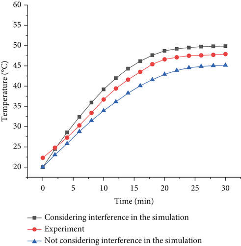
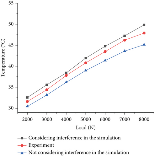
Figure 16 shows the steady-state temperature comparison between the simulation results and the experimental results of the cutter bearing under different loads. The figure shows that the simulated temperature of the bearing is in good agreement with the experimental temperature, and both show an increasing trend with increasing load. Because the measured temperature position is the cutter tool body, the bearing outer ring transfers heat to the tool body via heat transfer. Therefore, the experimental temperature is lower than the simulated temperature. The maximum difference between the simulated temperature and the experimental temperature, considering the interference fit factor, is 1.94°C, and the experimental error is within a reasonable range. However, the maximum temperature difference between the simulation and the experiment, without considering the bearing interference fit factor, is 2.77°C. The simulation and experimental errors, considering the interference fit factor, are smaller. This finding shows that the model can accurately predict the cutter bearing temperature under heavy load conditions and provides a theoretical basis for predicting the cutter temperature in practical engineering.
To attenuate the effect of noise on the experimental results, the average median filtering method is used for filtering. A comparison of the experimental and simulated vibration time domains for the bearings under a cutter pushing load of 5000 N after the filtering process is shown in Figure 17a. The time domain waveform trends of the simulation without thermal displacement and interference fit, the simulation with thermal displacement and interference fit, and the experiment are basically similar. Moreover, the experimental and simulation results are approximately similar in terms of amplitude fluctuations.
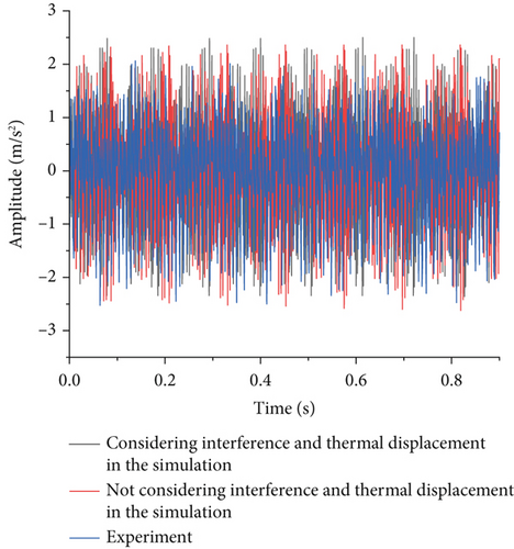
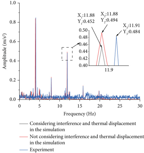
Figure 17b shows a comparison between the experimental vibration signals and the simulated vibration displacement signals in the frequency domain. The amplitudes of vibration acceleration at 3X frequency for the simulation not considering thermal displacement and interference fit, the simulation considering thermal displacement and interference fit, and the experiment are 0.452, 0.494, and 0.484 m/s2, respectively. A slight increase in the interference fit makes the fit between the components of the bearing closer and the operation of the bearing more efficient. The amplitudes of the experiment and simulation are similar. However, the maximum error between the experimental results and the simulation results is 7.08% because of the interference of thermal displacement. This finding reflects that thermal displacement and interference fit are the main factors affecting bearing vibration.
5. Conclusion
- 1.
Heat transfer science is combined with Palmgren’s experience formula to establish a temperature field model for TBM cutter bearings. The thermal displacement shows a nonlinear incremental relationship with temperature. Owing to friction and Hertzian contact forces, the roller has the highest temperature increase, followed by the cage, inner ring, and outer ring.
- 2.
Considering the effects of thermal displacement and heavy loads, the bearing radial thermal displacement tends to increase nonlinearly with increasing cutter thrust. When the load increased from 2000 to 8000 N, the change in fit caused by the temperature rise increased from 4.45 to 8.61 μm.
- 3.
The thermal displacement and interference fit have a more pronounced effect on the vibration characteristics. The TBM cutter bearing dynamics model developed in this paper has high computational accuracy, with a maximum error of 7.08%.
Conflicts of Interest
The authors declare no conflicts of interest.
Funding
This study was supported by the National Natural Science Foundation of China (10.13039/501100001809) (62173238 and 52207134), the Department of Science and Technology of Liaoning Province (10.13039/501100012131) (2024-MSLH-401), and the Education Department of Liaoning Provincial Program for Young Talents (JYTQN2023394 and LJ222410153061).
Open Research
Data Availability Statement
The data that support the findings of this study are available from the corresponding authors upon reasonable request.


