Numerical Assessments on Laminar Airflow, Thermal Characteristic, and Performance Improvement in a Round Tube Equipped With Combined Vortex Generators
Abstract
A round tube heat exchanger (RTHE) with combined vortex generators (CVGs) is subjected to numerical assessments of its airflows and thermal characteristics. The CVGs are V-shaped ribs and rectangular winglets. The effects of CVG arrangement (A-1, A-2, and B), blockage ratio (b1/H and b2/D), and airflow direction (+x, −x) on airflow and thermal behavior are considered. To solve the numerical problem, a commercial program’s finite volume technique is chosen. Presenting streamlines, fluid temperature distributions, and local Nusselt number contours (on the tube wall) are the numerical findings obtained in the RTHE fitted with the CVG. The study presents the performance analysis of RTHE using dimensionless variables, including the thermal enhancement factor (or thermal performance factor), averaged friction factor, and averaged Nusselt number. The numerical results indicate that the general flow configuration in the RTHE is dramatically altered by the CVG. The mixing quality of the fluid seems to be enhanced. The vortex flows are found through the RTHE. As a result of the vortex flows impinging on the RTHE wall, the thermal boundary layer (T-BL) over the heat transfer surfaces changes. Enhancing the convective heat transfer coefficient, heat transfer ability, and thermal performance in the RTHE is mostly because of the reduction of the T-BL thickness. When compared to a smooth round tube, the maximum enhanced heat transfer of the RTHE fitted with the CVG is 13.83 times greater. Furthermore, at Re = 2000, type B, b1/D = 0.15, b2/D = 0.05, and V-Upstream scenario, the optimal TEF is 3.81.
1. Introduction
Many laboratories, research groups, and industries are focusing on enhancing heat exchanger performance due to the current global energy consumption situation. Improving heat exchanger performance can significantly contribute to energy conservation and management. Consequently, various methods have been developed to enhance heat exchangers. Two primary approaches used are active and passive methods. The active method increases the heat exchanger’s heat transfer rate by applying external energy, such as vibration. In contrast, the passive method involves installing small obstacles—known as vortex generators, turbulators, or vortex producers—within the heat exchanger to alter flow and thermal behavior. The augmentation of heat transfer rates is influenced by these changes in flow dynamics. Investment and operating costs are crucial factors to consider when developing heat exchanger performance. As a result, the passive method is often selected as the first choice in many developments. Additionally, the use of nanofluids is another effective passive method for increasing heat transfer rates. Nanofluids can sometimes be effectively combined with vortex generators for enhanced performance. However, their production costs remain a concern for manufacturers due to their relatively high prices and the challenges associated with their manufacturing.
Vortex generators come in several forms. A few types of vortex generators are the rib, groove, baffle, wing, winglet, etc. The vortex generators’ type, shape, size, arrangement, and other characteristics have significant consequences on how the heating and cooling system’s flow topology changes and how heat transfers. Reports on the improvements in heat exchanger performance achieved by the passive approach have been published by numerous researchers. The experimental and numerical investigations are selected to address these concerns.
The thermal-hydraulic performance of a tube bank heat exchanger with circular-slice-shaped winglets was numerically studied by Tepe and Yilmaz [1]. Their results showed that the performance evaluation criterion increased to 1.356 with this winglet design, reducing the required total heat transfer area by 36.60% compared to a bare tube heat exchanger for the same heat duty and pumping power. Ekrani et al. [2] investigated a circular tube equipped with delta winglet vortex generators, finding enhanced heat transfer due to boundary layer disruption and whirling flow, with a maximum thermal enhancement factor (TEF) of 2.18. Akcay [3] demonstrated performance improvement in a periodic corrugated channel with discrete V-type winglets, with the highest thermal performance factors of 5.71, 4.68, and 5.17 for perforated winglet, solid winglet, and nonwinglet designs, respectively. Syaiful et al. [4] used concave delta winglet vortex generators in a tested channel, achieving a 53.58% increase in convection heat transfer compared to the baseline. Li et al. [5] reported the multiobjective optimization and thermal-hydraulic performance of microchannel heat exchangers with double delta winglet vortex generators, with a best performance criterion of 1.89. Ali et al. [6] observed the highest TEF of 1.15 in a channel with delta winglet pairs at a 35° attack angle and −45° inclination. Saini et al. [7] investigated the performance of a fin-and-tube heat exchanger with a curved delta winglet vortex generator and found increases in the averaged Nusselt number of 42.51% and 77.25% at Reynolds numbers of 2000 and 400, respectively. Ryu et al. [8] studied the effects of winglet shape on axial-flow fan performance and found that winglets increased gap-vortex strength, negatively affecting fluid flow and acoustics. Zheng et al. [9] reported novel self-joining winglet vortex generators for improved heat transfer in round tubes, with a maximum TEF of 1.27. Finally, Deng et al. [10] examined film cooling with various winglet vortex generators and observed a maximum heat transfer augmentation of 11.45%. Zhang et al. [11] found that the new bent winglet outperformed the standard winglet in surge motion by 14.5%. Wu et al. [12] investigated heat transfer and fluid flow in a tube with multi-V-winglet vortex generators, reporting a maximum performance evaluation factor of 2.83 for a configuration with eight winglets, each featuring holes and a 25 mm pitch. Wang et al. [13] studied the thermohydraulic performance of a tube with various punched winglets, concluding that the highest TEF of 1.14 occurred at Re = 9090 for winglets with round holes. Maithani et al. [14] analyzed exergy efficiency in a solar heat collector with wavy delta winglets, achieving a maximum exergy efficiency of 29.18% with specific geometric configurations. Saini et al. [15] demonstrated performance improvements in a fin-and-tube heat exchanger using curved trapezoidal winglet vortex generators with circular punched holes, resulting in a 75.25% increase in the Nusselt number at Re = 400 and 40.10% at Re = 2000, though with a significant pressure drop increase. Modi and Rathod [16] experimentally evaluated the thermal performance of a fin-and-tube heat exchanger with modified rectangular winglet vortex generators, noting a significant heat transfer coefficient increase at the cost of higher pressure loss. Naik et al. [17] explored the thermal and flow characteristics of a curved rectangular winglet vortex generator, emphasizing the importance of secondary flow in enhancing heat transfer. Heriyani et al. [18] used perforated concave rectangular winglet-pair vortex generators, achieving a TEF of 1.29. Zhao et al. [19] improved the thermohydraulic efficiency of a plate fin-tube heat exchanger by using straight and curved rectangular winglet vortex turbulators, with the latter performing better overall. Kumar and Dalal [20] numerically investigated the thermal and hydraulic characteristics of a finned tube with rectangular winglets and shear-thinning fluids, finding increases in the Nusselt number and friction loss by 124%–186% and 111%–133%, respectively. Yalçınkaya and Durmaz [21] reported a jet impingement cooling study with elongated nozzle holes on a curved surface roughened with V-profile ribs, achieving a maximum thermal performance criterion of 1.07. Yalçınkaya et al. [22] numerically studied elliptical-shaped pin-toughened surfaces for jet impingement cooling, achieving a 35.82% increase in the Nusselt number at Re = 16,250. They further examined elliptical pins on a semicircular concave surface, achieving a 55.68% heat transfer enhancement and a thermal performance criterion of 1.10 [23]. Yalçınkaya et al. [24] also investigated aerofoil-shaped fins on a curved target surface, achieving a thermal performance criterion of 1.12, and they studied slot-shaped pins in extended jet impingement cooling, noting significant effects on convective heat transfer uniformity [25].
In previous research, the development of vortex generators using V-shaped or V-like structures has attracted significant interest from many researchers. This is because such shapes are highly effective at generating vortex flows, which greatly enhance heat transfer rates. Most studies have installed V-shaped vortex generators either on the surface of heat exchanger tubes or in the center of the tube. Installing them at the center offers advantages in terms of ease of installation and maintenance, while installation on the surface of the heat exchanger tube increases the strength of the vortex flow, which positively affects the heat transfer coefficient. However, the simultaneous installation of V-shaped vortex generators at both positions—on the surface of the heat exchanger tube and in the center—has not been explored. Therefore, this study introduces the use of both installation positions, which play a crucial role.
According to the published works, V-rib and rectangular winglets are two efficient vortex generators for the heat exchanger performance development of various systems. Therefore, the V-rib and rectangular winglets were developed for the present work. The size, arrangement, and shape of the vortex generator, which significantly affect the change in flow and thermal behavior, are investigated. The numerical method with the finite volume method (a commercial code or program) that helps with flow and heat transfer descriptions in the tested section is selected. The numerical method also helps to save on the investment cost of the investigation. In fact, we can use experimental setups to study flow behavior and heat transfer in heat exchanger tubes. However, special techniques are required for observation, such as liquid crystals. The use of these techniques incurs relatively high costs in research studies. Therefore, the researchers opted to use numerical studies instead.
In this article, the authors present the study, which can be divided into the following sections: Section 2 explains the details of the developed numerical model. Section 3 presents the numerical setting, boundary conditions, and equation solvers. Section 4 discusses the validation of the model. Section 5 addresses the topic of numerical results, and this section is further divided into subsections. Section 5.1 presents the flow and heat transfer behavior in heat exchanger tubes, while Section 5.2 analyzes thermal performance in terms of dimensionless variables. The conclusions of the study are presented in Section 6.
2. Numerical Model Description
As shown in Figure 1, the component tested in this study is a round tube heat exchanger (RTHE) equipped with combined vortex generators (CVGs). The CVG consists of a V-rib and a rectangular winglet. Different arrangements of CVGs in the RTHE resulted in three distinct models, labeled A-1, A-2, and B.

In model A-1 (type A-1), rectangular winglets are arranged in an inline configuration on the tube wall, facing away from the V-ribs, which are positioned in the center of the tested tube. In model A-2 (type A-2), V-ribs and rectangular winglets are installed in a similar pattern, but with added gap spacings between the tube wall and the left-right sections of the V-ribs. These gap spacings are intended to (1) increase vortex strength, (2) increase the number of vortex cores, and (3) reduce pressure loss. Model B (type B) features rectangular winglets inserted in the center of the tested tube, with V-ribs arranged in an inline configuration on the tube wall, facing in the opposite direction.
The tested tube diameter, D, equals 0.05 m. L is the periodic length, which equals the tube diameter; L = D. P is pitch spacing, and P/D = 1 for all investigated cases. The vortex generators with a flow attack angle of 30° were found to have the best improved heat transfer rate and thermal performance in the published work [26]. Consequently, under all conditions, a flow attack angle of 30° is selected. The vortex generator height is represented by “b.” b1 is the upper-lowered vortex generator height, while b2 is the middle vortex generator height. The range of values for b1 and b2 is 0.05D–0.20D. Positive x (+x) and negative x (−x) are taken into consideration in air-flow directions. The flow directions are called V-Downstream (V-tip pointing downstream) and V-Upstream (V-tip pointing upstream) for +x and −x flow directions, respectively. Laminar airflow with Reynolds numbers of 100–2000 (inlet condition) is studied.
The model’s accuracy is ensured with the use of hexahedral mesh, which is well-suited for studies aimed at examining heat transfer behavior. An unstructured mesh was employed, with finer mesh density near surface areas. The y+ value of the numerical model was checked according to meshing guidelines, and it is approximately 1 in all cases studied. Additionally, the appropriate mesh count for the model was examined, and the results of this study are described in Section 4.
3. Numerical Setting, Boundary Conditions, and Equation Solvers
Airflow and temperature variation in the RTHE are considered to be steady and fully developed in three dimension (3D). Because of its low velocity, the laminar flow is incompressible. The viscous dissipation and the body force terms are assumed to be negligible. As the thickness of CVGs is very thin, forced convection is thus considered the major contribution to heat transfer in the RTHE. The governing equations are as Ref. [26]. The equations relevant to this research include the Reynolds number, Nusselt number, friction factor, and TEF, which are the dimensionless variables used in this study.
The initial fluid temperature of the entering laminar flow is 300 K (27°C), and its Prandtl number is Pr = 0.707. The working fluid’s thermal characteristics remain constant since the heating process causes the temperature of the fluid to vary by only about ±10 K. Table 1 is a tabulation of the boundary conditions for the RTHE’s computing domain that has the CVGs installed.
| Zone | Boundary conditions | |
|---|---|---|
| Momentum equation | Energy equation | |
| Entry zone | Periodic boundary | Periodic boundary |
| Exit zone | Periodic boundary | Periodic boundary |
| RTHE wall | No-slip condition | Wall temperature of 310 K (uniform and constant setting) |
| CVG | No-slip condition | Insulator, have no any heat transfer mode |
Boundary conditions are defined according to references [26–30]. The inlet and outlet are set as periodic because the model represents a long industrial pipe with fully developed flow and heat transfer. The walls of the heat exchanger are maintained at a uniform constant surface temperature. Based on references and preliminary study results, specifying the wall as having a constant surface temperature or constant heat flux yields the same values for both flow and heat transfer in the laminar flow regime. The CVG is modeled as an insulating plate with negligible thickness. In actual industry applications, CVG plates are typically made from aluminum and are installed in heat exchanger tubes using an insertion method for ease of installation and maintenance. This method creates a small gap between the CVG plates and the tube surface, resulting in negligible or minimal heat conduction through the CVG plates compared to the convective heat transfer. Additionally, the CVG plate is modeled as an insulator because, in real systems, materials with negligible thermal conductivity may be used in manufacturing.
In the present research, the simulation of working fluid flow and thermal characteristics through the RTHE with CVGs is performed using a commercial finite volume method code. The power-law numerical scheme is employed to discretize the momentum and continuity equations, while the QUICK numerical scheme is used for the energy equation. Comparison of the power-law, SOU, and QUICK schemes for the momentum and continuity equations revealed that all three methods produced identical results for both flow and heat transfer. For all variables, the normalized residual must be less than 10−5, but to meet the convergence requirements for the energy equation, it must be less than 10−9.
4. Numerical Validation
In numerical modeling studies, a crucial step is model validation, which ensures that the results are reliable. In the laminar flow regime, model validation can be divided into two parts: validation of the empty tube and grid sensitivity analysis (grid independent/optimum grid cell) [26–30].
Figure 2 presents smooth validations of RTHE. The current model’s Nusselt number and friction factor are validated by comparing them with the correlation data [31]. It can be observed that as the Reynolds number is increased, the friction factor falls while the Nusselt number stays unchanged. The friction factor and Nusselt number trends are similarly found for both sources. The deviations of the friction factor and Nusselt number are 0.8% and 0.04%, respectively.
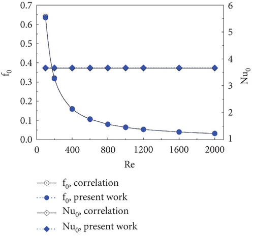
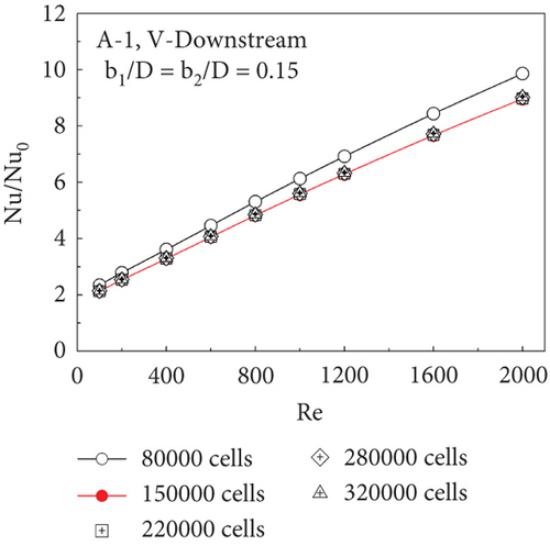
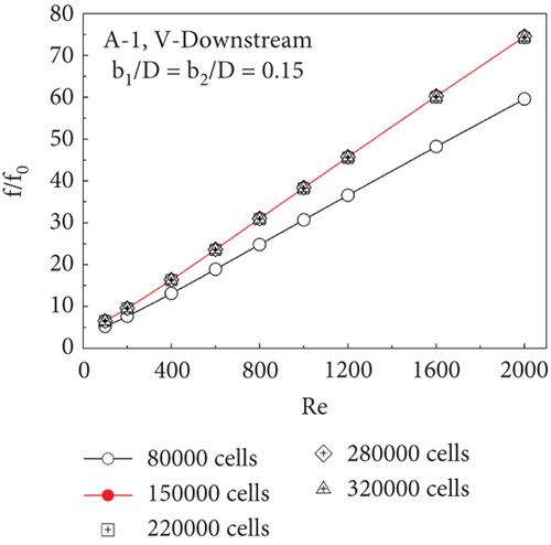
Figure 3a,b show the variations of Nu/Nu0 versus Re and f/f0 versus Re, respectively, for type A-1 CVG at b1/D = b2/D = 0.15, V-Downstream, with various grid elements (80,000, 150,000, 220,000, 280,000, and 320,000 cells). As shown in the figures, it is detected that the Nu/Nu0 and f/f0 ratios do not vary for the numerical model with grid elements of 150,000–320,000 cells. In order to conserve workstation resources and explore time spans, the numerical model’s ideal grid element can help. For every case, a control grid element consisting of approximately 150,000 cells is used in the development of the numerical model for this study.
It is visible from the validated result that the developed model can precisely predict the flow and heat transfer processes in the RTHE that has the CVG inserted.
5. Numerical Results and Discussions
5.1. Flow Description and Thermal Mechanism
The RTHE equipped with the CVG is shown in Figure 4a,b, illustrating the working fluid-flow structure (streamlines in cross-sectional planes) and thermal behavior (fluid temperature contours in cross-sectional planes), respectively. The installation of the CVG alters the general flow structure within the RTHE by inducing vortex flows. Vortex flow occurs when air passes through the CVG, creating a pressure difference between the front and rear of the CVG, which in turn intensifies the vortex flow. As the height of the CVG increases, the pressure difference also increases, leading to more intense vortex flow. Depending on the x/D position, each plane contains four to eight primary vortex cores, with slight variations in their positions.
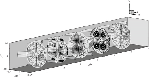
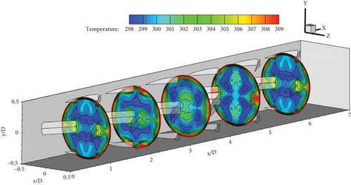
The vortex flow impacts the heat transfer surface (the tested tube wall) as it approaches the RTHE wall. The interaction between the vortex flow and the heat transfer surface affects the variation in the thermal boundary layer (T-BL). An increase in the CVG height results in a greater pressure drop across the CVG, which intensifies the impinging flow and reduces the T-BL thickness. This reduction in T-BL thickness enhances the heat transfer coefficient on the heat exchanger surface, which is directly proportional to the heat transfer rate. As shown in Figure 4b, the T-BL thickness decreases (depicted as the red layer on the outer side of the plane), while the blue layer, indicating lower fluid temperature, originates from the plane’s center. This suggests improved fluid blending quality within the RTHE. Enhanced fluid blending contributes to increased thermal efficiency and a higher heat transfer rate.
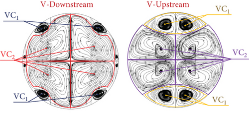
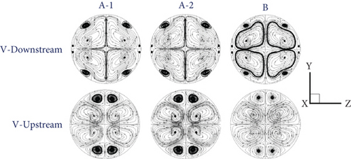
Figure 5 presents the vortex flow description of the RTHE equipped with the CVG for V-Downstream and V-Upstream directions. The vortex flow can be divided into two parts. The first part is called “VC1,” while the second part is named “VC2.” The VC1 is produced from the CVG, which is placed on the RTHE wall, while the VC2 is induced by the CVG, which is inserted in the middle of the RTHE. The VC1 directly affects the impinging flow on the RTHE wall, while the VC2 can help augment fluid blending quality. The modifications in the flow structure (streamlines in cross-sectional planes) with different b1/D and b2/D values can be seen in Figure 6. The VC1 extremely extends when augmenting b1/D, while the VC2 slightly expands when rising b2/D. The change in vortex flow with b1/D and b2/D is similar for all CVG types. Comparing the V-Upstream case with the V-Downstream circumstance, the latter offers the opposite rotation. Figure 7 demonstrates the streamlines in the cross-sectional plane, or flow structure, of the RTHE fitted with a CVG, depending on the flow directions and CVG types. As seen in the figure, the main flow configuration of various CVG types and flow directions at similar b1/D and b2/D is similar.
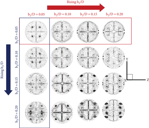
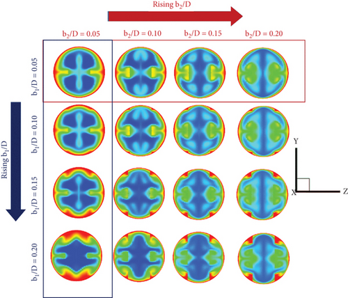
The temperature contour changes in the cross-sectional plane for the RTHE fitted with the type A-1 CVG, V-Downstream, with different b1/D and b2/D, are shown in Figure 8. In every example that was examined, the T-BL was disturbed, and the fluid blending quality was enhanced. The disturbed T-BL can be observed by the change in the red layer near the RTHE wall. The red layer thickness decreases when increasing b1/D and b2/D because of the increasing vortex strength. The fluid blending quality (blue contour distributions) in the RTHE equipped with the CVG also rises when increasing the b1/D and b2/D.
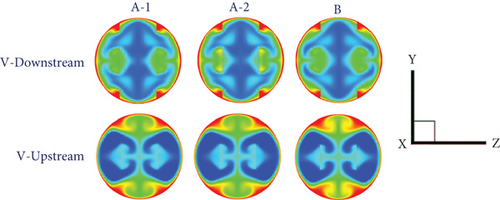
In Figure 9, the temperature contours in the cross-sectional plane of the RTHE fitted with the CVG at various CVG types and flow directions are presented. The thermal behavior of all CVG types at similar flow directions follows a similar pattern. In terms of fluid blending, the V-Downstream case outperforms the V-Upstream case. In the V-Downstream example, the disrupted T-BL is plainly visible.
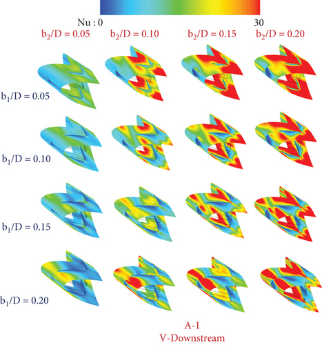
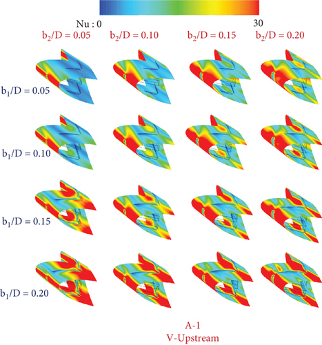
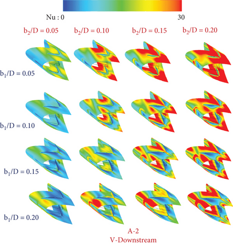
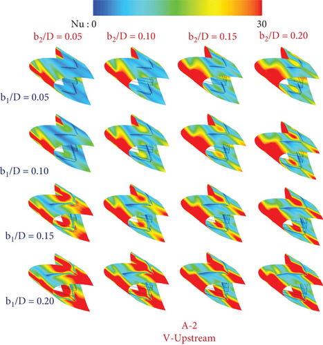
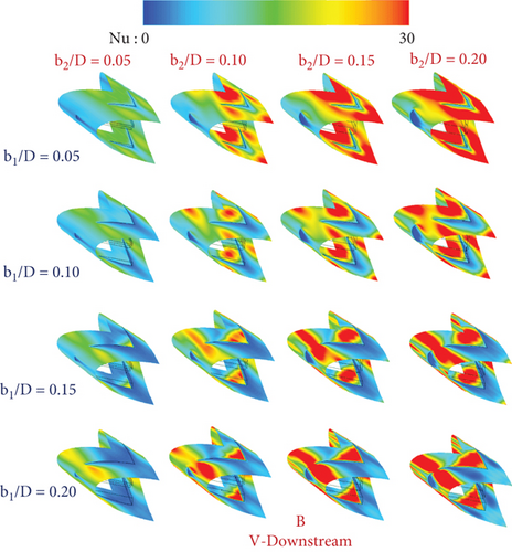
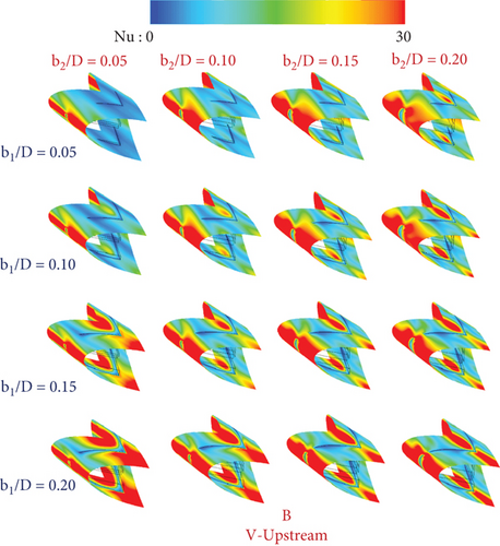
On the tube surface of the RTHE fitted with type A-1 (V-Downstream), type A-1 (V-Upstream), type A-2 (V-Downstream), type A-2 (V-Upstream), type B (V-Downstream), and type B (V-Upstream), respectively, are shown as the local Nusselt number contours in Figures 10a, 10b, 10c, 10d, 10e, and 10f. Red contours mean a high Nusselt number, while blue contours mean a low Nusselt number. The red contours extend when increasing b1/D and b2/D as a consequence of the enhancement of the vortex strength. A similar Nu-distribution pattern can be observed for all CVG types in a similar flow direction.
5.2. Performance Assessments
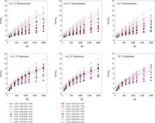
The Nusselt number of the RTHE equipped with the CVG, Nu, is compared to the Nusselt number of the smooth round tube, Nu0, to examine the thermal characteristics of the RTHE installed with the CVG, or Nu/Nu0. Figure 11a shows the relationships between Nu/Nu0 versus Re for the RTHE fitted with the CVG at different b1/D, b2/D, CVG types, and fluid-flow directions. When Nu/Nu0 > 1, the heat transfer rate resulting from the CVG installation in the RTHE is greater than that of the smooth round tube. Raising the Reynolds number and CVG height results in an increase in the Nu/Nu0. The Nu/Nu0 is 1.44–13.31, 1.21–13.64, 1.40–12.72, 1.21–13.83, 1.43–12.39, and 1.20–11.32 for type A-1 (V-Downstream), type A-1 (V-Upstream), type A-2 (V-Downstream), type A-2 (V-Upstream), type B (V-Downstream), and type B (V-Upstream), respectively.
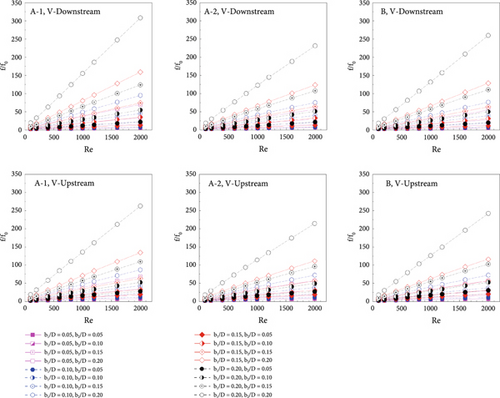
In addition to increasing the heat transfer rate, the CVG addition increases pressure loss in the RTHE. The optimal pressure loss may bring the best thermal performance. The pressure loss in the RTHE is reported in relation to the ratio of the friction factor of the RTHE equipped with the CVG, f, to the friction loss of the smooth round tube, f0, f/f0. The relationships between the f/f0 and the Reynolds number for different CVG types and flow directions are shown in Figure 11b. In every example that was examined, the friction factor of the RTHE outfitted with the CVG was greater than that of the smooth round tube (f/f0 > 1). The f/f0 rises when the Reynolds number and CVG height are raised. The highest blockage ratio, b1/D = b2/D = 0.20, of all CVG types and flow directions produces a very large pressure loss. The f/f0 is 2.09–308.49, 2.09–262.79, 2.10–231.58, 2.11–214.44, 2.03–260.12, and 2.07–242.43, respectively, for type A-1 (V-Downstream), type A-1 (V-Upstream), type A-2 (V-Downstream), type A-2 (V-Upstream), type B (V-Downstream), and type B (V-Upstream).
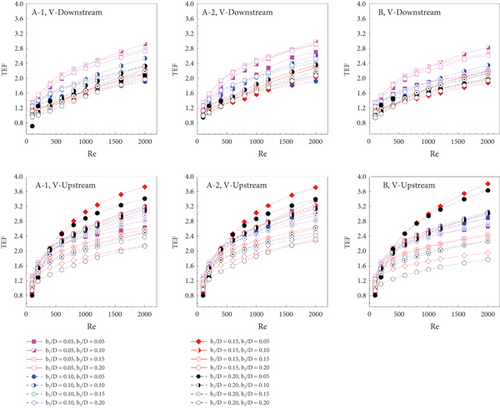
The CVG addition in the RTHE enhances heat transfer rate and pressure loss. The enhanced heat transfer rate is beneficial for the heat transfer system, while the augmented pressure loss is not. As a result, TEF, or increased heat transfer rate at a comparable pumping effort, is used to describe the CVG installation. Figure 11c shows the relationships between the TEF and the Reynolds number for the RTHE equipped with the CVG in different conditions. TEF > 1 indicates that the CVG addition in the RTHE is almost always greater than that of the smooth round tube. In all investigated cases, the TEF rises when the Reynolds number is increased. The TEF is observed to be maximum at Re = 2000. Type A-1 (V-Downstream), type A-1 (V-Upstream), type A-2 (V-Downstream), type A-2 (V-Upstream), type B (V-Downstream), and type B (V-Upstream) have TEFs of 2.92, 3.72, 2.98, 3.70, 2.82, and 3.81, respectively. For all CVG types, the greatest TEF is observed at b1/D = 0.05 and b2/D = 0.10 for the V-Downstream case and b1/D = 0.15 and b2/D = 0.05 for the V-Upstream case. Therefore, b1/D = 0.05 and b2/D = 0.10 are suggested for the V-Downstream vortex generator, while b1/D = 0.15 and b2/D = 0.05 are recommended for the V-Upstream vortex generator.
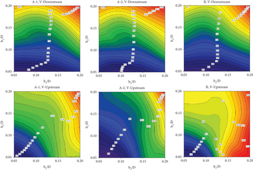
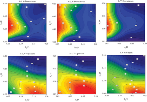
Figure 12a shows the Nu/Nu0 contours at Re = 2000 with different CVG types and flow directions. With the exception of type B CVG, where the maximum Nu/Nu0 is observed at b1/D = 0.05 and b2/D = 0.20, the maximum Nu/Nu0 is observed at b1/D = b2/D = 0.20 for practically all CVG types. The TEF contours for different CVG types and fluid-flow directions at Re = 2000 are shown in Figure 12b. Considering a similar flow direction, it is seen in the figure that the greatest TEF is found at similar b1/D and b2/D conditions.
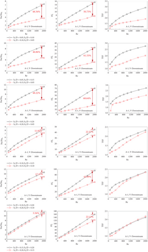
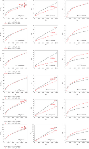
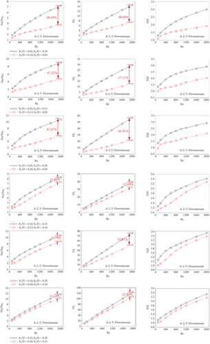
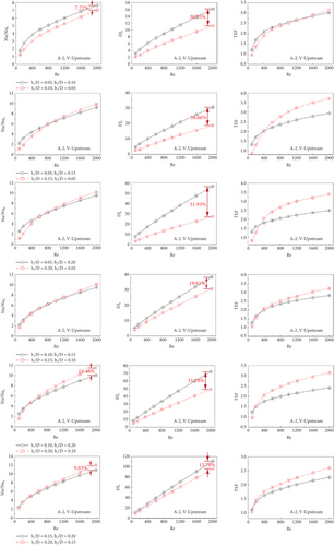
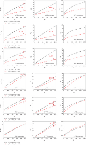
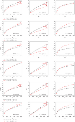
Figures 13a, 13b, 13c, 13d, 13e, and 13f present the variations of Nu/Nu0, f/f0, and TEF comparisons for some cases of type A-1 (V-Downstream), type A-1 (V-Upstream), type A-2 (V-Downstream), type A-2 (V-Upstream), type B (V-Downstream), and type B (V-Upstream), respectively. The comparison cases are concluded in Table 2.
Black line |
Red line |
|
|---|---|---|
| Case No. 1 | b1/D = 0.05, b2/D = 0.10 | b1/D = 0.10, b2/D = 0.05 |
| Case No. 2 | b1/D = 0.05, b2/D = 0.15 | b1/D = 0.15, b2/D = 0.05 |
| Case No. 3 | b1/D = 0.05, b2/D = 0.20 | b1/D = 0.20, b2/D = 0.05 |
| Case No. 4 | b1/D = 0.10, b2/D = 0.15 | b1/D = 0.15, b2/D = 0.10 |
| Case No. 5 | b1/D = 0.10, b2/D = 0.20 | b1/D = 0.20, b2/D = 0.10 |
| Case No. 6 | b1/D = 0.15, b2/D = 0.20 | b1/D = 0.20, b2/D = 0.15 |
For V-Downstream of all CVG types, black lines perform higher Nusselt numbers and friction losses than red lines. The different Nusselt numbers and friction factors decrease when increasing b1/D and b2/D. The black lines provide better TEF than the red line, except for Cases Nos. 5 and 6. The TEF of both lines seems to be very close.
For V-Upstream of all CVG types, black lines perform a higher Nusselt number than the red line in Case No. 1 but slightly lower for Case Nos. 2–6 when considering Re = 2000. The black lines show a higher friction factor than the red lines in all investigated cases. The difference in f/f0 between red and black lines is found to be very large for a low blockage ratio. The different f/f0 of the red and black lines decrease at high blockage ratios. The red lines give greater TEF than the black lines, except for case no. 1, where the TEF of both lines is very close.
The results of the study have been compared with previously published research focusing on enhancing the performance of V-shaped vortex generators, as shown in Figure 14. From the figure, it can be observed that the vortex generator CVT (current study) results in a lower heat transfer rate compared to previous studies [27, 32] but provides a higher heat transfer rate compared to the reference study [33]. Considering the maximum TEF values in each study, the current study demonstrates a higher TEF value compared to the reference studies [32, 33] and is only slightly lower than the study [27].
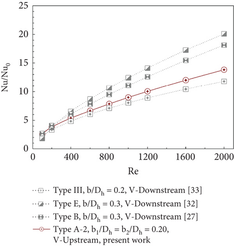
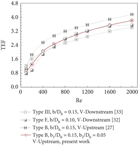
This comparison includes research on vortex generators designed to enhance heat transfer in square-cross-section ducts. Typically, heat transfer in square ducts is greater than in round tubes when considering dimensionless variables. The comparison results indicate that, although heat exchangers with vortex generators (in circular cross-sections) may show lower heat transfer rates compared to those with square cross-sections, the TEF values are not significantly different.
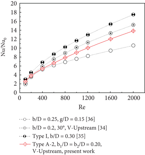
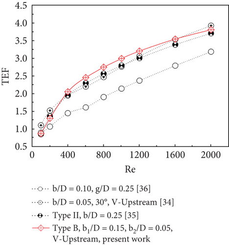
This research has been compared with previously published studies focusing on the development of vortex generators in circular cross-section tubes, as shown in Figure 15. From the figure, it can be observed that the current study exhibits a lower heat transfer rate compared to studies [34, 35] but a higher rate than study [36]. When considering the TEF values, the current study demonstrates a higher TEF compared to the other studies, except at a Re value of 2000, where the TEF of the current study is slightly lower than that of the study [34]. The comparison between Nu/Nu0 and TEF for this research and previously published studies [27, 32–36] is summarized in Table 3.
| Case | Cross-section | Maximum Nu/Nu0 |
|---|---|---|
| Type A-2, b1/D = b2/D = 0.20, V-Upstream, present work | Round tube | 2.53–13.82 |
| Type III, b/Dh = 0.2, V-Downstream [33] | Square duct | 2.25–11.80 |
| Type E, b/Dh = 0.3, V-Downstream [32] | Square duct | 1.80–20.10 |
| Type B, b/Dh = 0.3, V-Downstream [27] | Square duct | 2.68–18.12 |
| b/D = 0.25, g/D = 0.15 [36] | Round tube | 2.16–10.56 |
| b/D = 0.2, 30°, V-Upstream [34] | Round tube | 1.92–15.16 |
| Type I, b/D = 0.30 [35] | Round tube | 3.03–17.46 |
| Case | Cross-section | Maximum TEF |
| Type B, b1/D = 0.15, b2/D = 0.05, V-Upstream, present work | Round tube | 0.87–3.81 |
| Type III, b/Dh = 0.15, V-Downstream [33] | Square duct | 1.22–3.42 |
| Type F, b/Dh = 0.10, V-Downstream [32] | Square duct | 0.78–3.54 |
| Type B, b/Dh = 0.15, V-Upstream [27] | Square duct | 1.02–4.16 |
| b/D = 0.10, g/D = 0.25 [36] | Round tube | 0.89–3.18 |
| b/D = 0.05, 30°, V-Upstream [34] | Round tube | 1.10–3.92 |
| Type II, b/D = 0.25 [35] | Round tube | 0.85–3.70 |
6. Conclusion
- •
The simulated validations, optimum grid elements, and plain round tube validation can be accepted. This means that the numerical model of the RTHE equipped with the CVG has reliability for flow and heat transfer prediction.
- •
The suggested flow and thermal configuration of the CVG-equipped RTHE are noted. The mechanisms in the tested tube are (1) generated vortex flow, (2) impinging flow on the tube wall, (3) improved fluid blending quality, and (4) a disturbed T-BL. The improved heat transfer and thermal performance of the RTHE are due to these mechanisms. Different CVG types in a similar fluid-flow direction have similar fluid flow and thermal mechanisms.
- •
While the upper-lower CVG (produces CV1) directly influences the impinging fluid flow over the RTHE wall and T-BL disturbance, the intermediate CVG (produces CV2) can aid in improving the fluid blending quality.
- •
The type A CVG has a slightly greater heat transfer ability than the type B CVG. The maximum heat transfer rate for the RTHE fitted with the CVG is 13.83 times that of the smooth round tube. The best TEF is 3.81, which is observed at b1/D = 0.15, b2/D = 0.05, type B CVG, and V-Upstream case at Re = 2000.
- •
For the V-Downstream CVG, the recommended circumstances are b1/D = 0.05 with b2/D = 0.10, and for the V-Upstream CVG, b1/D = 0.15 with b2/D = 0.05.
- •
Recommendations for using CVG vortex generators in the real-world industry: CVG plates can be applied to various types of heat exchangers, such as shell-and-tube heat exchangers and double-pipe heat exchangers. They are suitable for use with both gaseous and liquid flows. However, it is important to ensure that CVG are securely installed, particularly for liquid flows in heat exchanger systems. In cases where the fluid is highly viscous and has high velocity, CVG may shift from their intended position. Such shifting could impact the flow structure and affect heat transfer performance.
- •
For future research, the researcher plans to study the structure of CVG under turbulent flow conditions. Additionally, the research will explore the impact of CVG spacing along the length of the pipe and investigate the flow and heat transfer characteristics in long pipes with installed CVG.
Nomenclature
Symbols
-
- b
-
- CVG height, m
-
- D
-
- round tube diameter, m
-
- f
-
- friction factor, friction loss
-
- h
-
- convective heat transfer coefficient, W m−2 K−1
-
- k
-
- thermal conductivity, W m−1 K−1
-
- L
-
- numerical model length/periodic length
-
- Nu
-
- Nusselt number
-
- p
-
- static pressure, Pa
-
- P
-
- pitch spacing, m
-
- Re
-
- Reynolds number
-
- T
-
- fluid temperature, K
-
-
- fluid mean velocity in square duct, m s−1
-
- ρ
-
- density, kg m−3
Subscripts
-
- Zero
-
- smooth round tube
-
- pp
-
- driving force
Abbreviations
-
- RTHE
-
- round tube heat exchanger
-
- CVG
-
- combined vortex generator
-
- TEF
-
- thermal enhancement factor ()
-
- T-BL
-
- thermal boundary layer
Conflicts of Interest
The authors declare no conflicts of interest.
Funding
The authors received no financial support for the research, authorship, and/or publication of this article.
Acknowledgments
The authors would like to thank Prof. Dr. Pongjet Promvonge for his suggestions.
Open Research
Data Availability Statement
Data are available on request due to privacy/ethical restrictions.


