Numerical Optimization of the Hydraulic and Hemolytic Performance of a Centrifugal Ventricular Assist Device Based on Impeller Flow Passage and Outlet Geometry
Abstract
As technology continues to advance and modern lifestyles become increasingly mechanized, the prevalence of heart disease is steadily growing. On the other hand, donor hearts ready for transplantation are limited worldwide. Therefore, blood pumps are a suitable alternative to help the patient during the waiting period and even until the end of life. Blood pumps must meet biological requirements, including adequate output pressure and flow rate, within an acceptable margin of safety in the event of blood damage. Reduction of pump size, blood exposure time, and blood damage such as hemolysis have been mentioned as important challenges in the design of blood pumps. Statistics show that 30% of the patients who use a left ventricular blood pump need a right ventricular blood pump due to right ventricular failure. The purpose of this research is to determine the effect of the geometrical shape of the impellers (flow passage) and the thrust tube geometry of the volute chamber on the pump’s hydraulic performance, the amount of axial and radial forces, and the amount of blood damage. So, for this study, six blades and two types of geometry for the volute chamber thrust tube were designed. This pump has been simulated using computational fluid dynamics used the Ansys CFX 17. Finally, the appropriate pump has been selected for low hemolysis index (HI). The HI calculated using the Lagrangian method is 0.00279 in the pump with a flow rate of 5 L per minute and 1100 rpm.
1. Introduction
Heart failure is a rising health concern around the world. Over the world, an appraised 26 million people toil from heart failure and in recent years, patient numbers have been increasing. Heart failure occurs when the heart loses its ability to pump enough blood to adequately meet the body’s demand for oxygen and vital nutrients [1]. In heart failure, heart dilation, reduction in cardiac muscle cell function, and water and sodium retention often occur [1]. The leading cause of heart failure is ischemic heart disease; because of atherosclerosis of the coronary arteries or a heart attack, some heart muscle cells die or undergo atrophy, and therefore the heart’s contraction power decreases [1]. Other causes include congenital defects, shunts, fistulas, cardiomyopathy, and hyperthyroidism [1]. Pharmacological treatment and heart transplantation can improve the symptoms of heart failure [1, 2]. Although heart transplantation is clinically successful, the number of heart donors is much lower than the number of patients requiring heart transplantation [1, 2]. Because of this, mechanical circulatory support devices play a crucial role either as a bridge to heart transplantation or as a long-term therapy for these patients [2–5].
Heart assist devices are divided into two groups: VAD and TAH. VAD is a device used to help the heart without removing the patient’s heart from the cardiovascular system in heart failure, while TAH is used as an anatomical and functional substitution for the heart. VADs are designed to help the left or right ventricle or simultaneously for both ventricles, but LVADs are most commonly used. Despite the benefits of LVAD implantation, right ventricular failure (RVF) has been observed in up to 30% of the patients following the procedure and its mortality rate has been up to 40% [5–7].
Some critical challenges for engineers in the design and manufacture of blood pumps include small size [8, 9], the ability to generate the pressure and flow required by the patients [9, 10], their durability [7, 11], easy design [8, 12–14], low blood damage [15–17], and easy controllability [18–20]. Blood damage occurs in blood pumps due to nonphysiological flow conditions such as flow separation [8], sharp edges in pump geometry [8, 12], recirculation zones [13], low or high shear [15], stagnation areas [18, 20], and narrow clearance [16, 17].
Blood damage in blood pumps includes two things that should be minimized: hemolysis and thrombosis.
Hemolysis is the rupture of the red blood cell membrane and the leakage of hemoglobin from the cell. Red blood cells are usually cut. When the shear is increased and the exposure time is long, the cell membrane ruptures and hemolysis occurs. Thrombosis means blood clotting and is a hemostatic mechanism of the body to prevent bleeding. Clotting is one of the causes of death in those who use cardiac assistive devices. The three main factors that play a major role in the formation of thrombosis are known as Wirshaw’s triple factors: hemodynamic changes in blood flow, abnormal changes in the vessel wall, and changes in blood composition. The stagnant points against the flow and where recirculation flows occur are high-risk and probable points for thrombosis. Thrombosis describes the formation of blood clots in areas with low shear, such as recirculating flow [3, 16, 21, 22].
There are two major models of hemolysis: strain-based and power-law models [23, 24]. The most common method used is the power-law model, which is related to shear stress and exposure time [23]. To estimate hemolysis using computational fluid dynamics (CFDs), two primary methods are employed: Eulerian and Lagrangian [25]. Both methods have inherent errors and are often used for comparative analyses in different devices [23–25].
Third-generation pumps are recommended as the most appropriate blood pumps and include nonpulsating centrifugal and axial pumps in which the impeller is suspended magnetically or hydraulically, which reduces component wear [26, 27]. Axial pumps generate high flow and low pressure [28], whereas centrifugal pumps generate high pressure and modest flow [29]. To generate high pressure, the impeller in the axial pump must work at higher speeds [28]. High velocity causes high shear on red blood cells, increasing the risk of hemolysis [26]. However, in centrifugal pumps, hemolysis is less than in axial pumps [29, 30]. In addition, axial pumps consume less energy and are easier to implant [6, 31].
Many studies have been done on improving the performance of pumps in vanes and body, which can be mentioned. Studying types of axial and centrifugal vanes, forward, backward, and straight, using the concentric circular arc method for impeller design, blade curvature, the gap between the impeller and the housing, the number of blades, and blade inlet and outlet angles [32–37].
Many studies have been conducted to improve the performance of blood pumps by focusing on vanes and pump bodies. These studies include examining different types of axial and centrifugal vanes, such as forward, backward, and straight vanes [38, 39]. In addition, the concentric circular arc method has been utilized for impeller design to enhance efficiency and performance [32]. Blade curvature has been investigated for its impact on hemolytic and hydraulic characteristics in centrifugal blood pumps [33]. The gap between the impeller and the housing plays a crucial role in minimizing blood damage and optimizing flow dynamics [34, 38]. Furthermore, the number of blades and the inlet and outlet angles of the blades have been analyzed to influence hydraulic performance and indicators of hemocompatibility [35]. Moreover, the investigation of cavitation characteristics in centrifugal blood pumps with variable speed has been explored to assess the effects of cavitation [36].
This study investigated the effect of the volute chamber’s geometry and the impeller’s geometry on the hydraulic and hemolytic performance of the centrifugal blood pump for the right ventricle. For the volute chamber geometry, the volute chamber designed in the previous study [37] was improved and a new geometry was intended. For the geometry of the impeller, in continuation of the previous study of this group, six impellers were designed with three types of flow passages (rectangular, circular, and oval) and two types of outlet geometries (with and without cutting) with the same cross-sectional area. The hydraulic performance and blood damage were investigated numerically using computational fluid dynamics, which is a comprehensive tool for designing and optimizing blood pumps that include hemodynamic analysis. The Food and Drug Association (FDA) has recently published a comprehensive report on pump simulation, setting it as the benchmark for accuracy and precision in numerical studies involving computational fluid dynamics and hemolysis using the power model. This study employed the specified standard pump to validate the numerical simulations. The findings of this study have significant clinical implications, potentially leading to the development of RVADs that offer enhanced performance and biocompatibility, ultimately reducing complications such as thrombosis and hemolysis and improving patient outcomes. After comparing different models, the most suitable right ventricular assist device design was ultimately selected.
2. Materials and Methods
2.1. The Pump Geometry
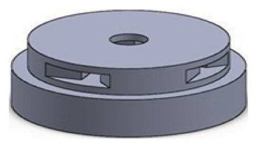
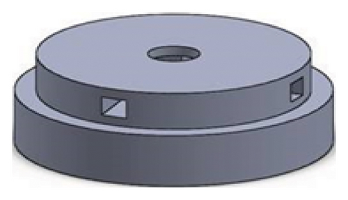
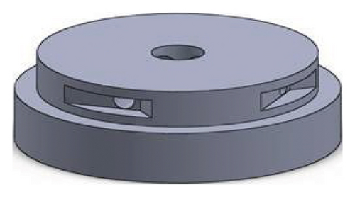
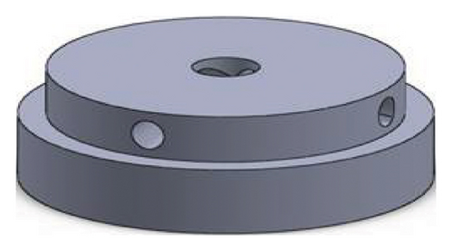
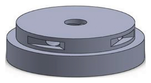
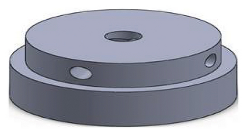
In this study, 12 configurations were designed and analyzed by combining impeller geometries and volute chamber designs. As mentioned in the introduction, three shapes of the impeller flow passage were considered: rectangular, circular, and elliptical. In addition, two types of impeller outlets were examined: with cutoff and without cutoff. Combining these three flow passage shapes with the two outlet types resulted in 3 × 2 = 6 impeller configurations. Two volute chamber designs were also considered. By combining the six impeller configurations with the two volute designs, a total of 6 × 2 = 12 configurations were obtained. In a previous study by this group, one volute design (the first design) was developed and analyzed for rectangular blades with a cutoff at the outlet. In this study, both the new and the previously designed volute models were simulated with all six impeller configurations. Due to the large number of potential configurations when considering the cutouts at the front and rear of the impellers separately and simulating two volute models with each impeller, the focus was limited to studying six impellers and two volute designs.
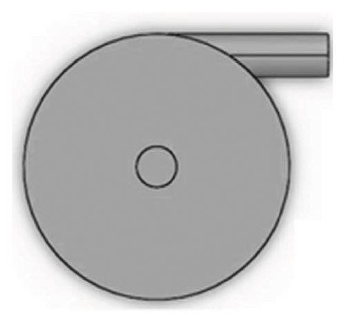
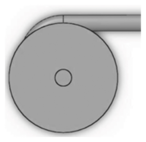
Figures 1 and 2 show the geometry of these blades and volute chambers. The blades with three flow passages (rectangular, circular, and elliptical) and two impeller outlets (with and without cutout) were designed. In the first volute chamber model, the thrust tube is connected to the volute chamber with a curve, while in the second model, the thrust tube is connected tangentially to the chamber without curvature. The characteristics of the pump are provided in Table 1.
| Design parameter | Value | Dimension |
|---|---|---|
| Dimp (impeller diameter) | 58 | mm |
| Din (inlet tube diameter) | 10 | mm |
| Dout (outlet tube diameter) | 10 | mm |
| Dvol (volute chamber diameter) | 62 | mm |
| H (impeller channel height) | 4 | mm |
| W (impeller channel width) | 5 | mm |
| N (number of flow passage (channel)) | 4 | |
| S (flow passage (channel) area) | 20 | mm2 |
| G (gap between impeller and chamber) | 2 | mm |
2.2. Governing Equation
2.2.1. Turbulence Modeling
By calculating the Reynolds number using equation (3), the resulting Reynolds number is greater than 105, indicating turbulent flow inside the pump. Therefore, turbulence models must be used for the simulation. Factors that influence the selection of an appropriate turbulence model include the physics of the flow, the computational time available, and other considerations. Therefore, no single turbulence model can be considered universally superior for all problem types. The suitable model should be chosen based on the specific characteristics of each problem [31, 40].
2.2.2. Hemolysis
In this simulation, the Lagrangian method [26, 44, 45] is used to measure hemolysis; shear stress acting on the RBCs accumulates over time as they move through the pump. The total damage inflicted on each RBC is determined by integrating the accumulated damage over short time intervals Δti from the pump’s inlet to the outlet. For each RBC, the initial time t0 at entry is considered zero [46].
Despite the differences in the absolute values of the HI obtained from experimental measurements and CFD predictions, these values can still be effectively used to compare blood damage across different models [26].
2.3. Numerical Solution
Nowadays, numerical simulation is used to analyze engineering topics, considering the high construction costs and the time-consuming nature of experiments. This study used the Ansys CFX 17 software for simulation. In the design of ventricular assistive devices, Ansys CFX software is widely used due to its good ability to analyze flow in pumps [47–50].
2.3.1. Grid Generation
In the meshing of the fluid domain inside the pump, impeller and volute chamber areas are considered for this pump, and each one has meshed separately. Due to the complex geometry of the impeller, the produced element has an unstructured, linear, and tetrahedral.
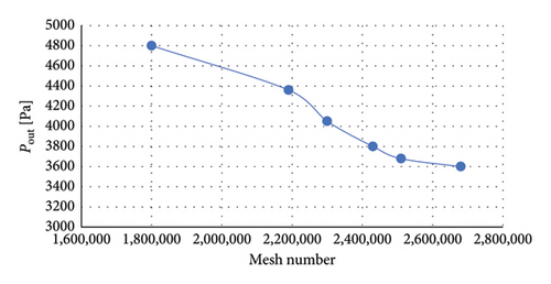
Mesh independence analysis determined that a computational mesh with 2.43 million elements was sufficient for accurate simulations. The pressure calculated at the outlet using this mesh differed by only 2.5% compared with the results from a finer mesh. Figure 3 shows mesh independence verification and mesh density illustration in impeller.

2.3.2. Boundary Conditions
Considering that blood exhibits Newtonian behavior at high shear rates of 100 and also considering the high shear rate in heart pumps, the assumption of the blood being Newtonian is acceptable [26, 51]. In this study, blood is modeled as a Newtonian fluid with a viscosity of 0.0035 Pa·s and a density of 1050 kg/m3 [52]. Pressure and volumetric flow rates are specified as boundary conditions at the inlet and outlet to simulate the pump’s performance. Specifically, a pressure of 5 millimeters of mercury (mmHg) representing the average intraventricular pressure in the right ventricle is applied at the inlet, while a volumetric flow rate of 5 L per minute is imposed at the outlet. In this geometry, multiframe reference (MRF) is used for simulation [40]. All the walls are simulated with a no-slip boundary condition. Due to the large number of models for simulation in this step, the simulation was performed at the design point (rotation speed of 1100 rpm and flow rate of 5 L/min). It is necessary to explain that various simulations have been carried out at different speeds to achieve the appropriate point of speed to produce the required head and flow rate of the pulmonary circulation. Finally, a speed of 1100 rpm has been chosen for this study.
2.3.3. Near-Wall Treatment
Wall functions are frequently considered when addressing wall effects in computational fluid dynamics. This method employs empirical formulas to impose appropriate conditions near the wall without resolving the boundary layer in detail. This significantly allows for using relatively coarse meshes when modeling the high-gradient shear layers adjacent to walls, thereby reducing the computational effort. Moreover, the wall function approach is compatible with all turbulence models available in CFX.
However, using extremely fine meshes in the near-wall region instead of the wall-function method requires more computational storage and longer simulation times. To mitigate this issue, CFX has developed a novel wall boundary treatment that automatically transitions from a low Reynolds number formulation to the one based on grid density, all without compromising accuracy [53, 54]. This innovative boundary treatment acts as an automatic wall function and is employed in this study as the wall-function method.
2.3.4. Convergence Criterion
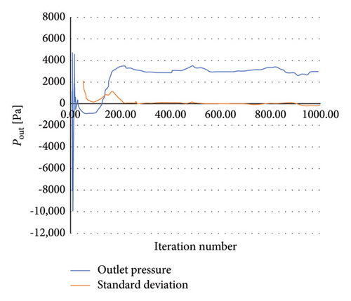
To achieve convergence of the numerical solution, a residual error threshold of 10−4 was set for mass and momentum equation, and the average pressure at the outlet was monitored. Figure 4 shows the pattern of changes in the average pressure at the outlet. According to the values related to the average pressure in 1000 iterations, changes less than 1 (mmHg) were observed; thus, the number of numerical solution iterations was chosen as 1000 iterations.
2.4. Validation
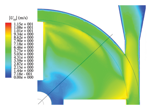
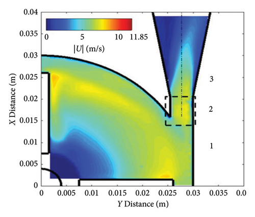
The FDA, recognizing the lack of a standardized validation method in numerical studies of ventricular assist devices and aiming to encourage researchers worldwide to use numerical models for predicting flow patterns and blood behavior in ventricular assist pumps, has provided details of the numerical simulations related to the pump introduced by the organization as a standard reference model. This pump is designed as a standard benchmark to check the accuracy and validity of calculation results compared with laboratory results [50]. This benchmark has been used in this study to validate of numerical simulation results.
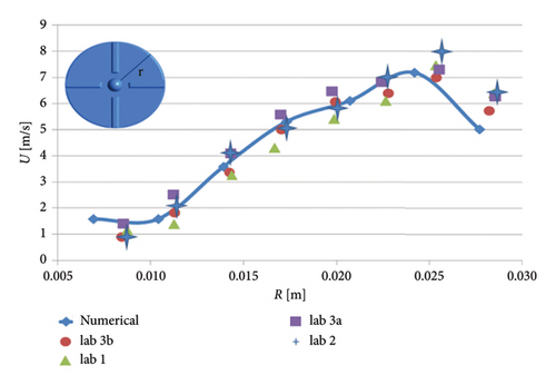
The FDA pump was simulated under operating conditions of a rotational speed of 3500 rpm and a flow rate of 6 L per minute. Velocity calculations were performed on a plane located 1.2 mm below the top surface of the blades. Figure 5 presents a quantitative comparison between the numerical simulation results obtained in this study and the particle image velocimetry (PIV) data provided by the FDA. As shown in Figure 5, the average speed discrepancies between the numerical results and measurements from various laboratories range from 8% (Laboratory 3b) to 16% (Laboratory 1).
3. Results
In this study, two volute chamber models and six impeller models were simulated, and the results were extracted to investigate the effect of the shape of the outlet of the volute chamber, the effect of the cross-section of the impeller flow passage, and the effect of the cut-out in the outlet geometries. Finally, the performance of the selected final pump was checked.
∗∗The pump with a volute chamber with a tangential outlet is named Configuration 1, and the pump with a volute chamber with a curved outlet is named Configuration 2.
3.1. Volute Chamber
3.1.1. Head
The head at a flow rate of 5 L/min and a rotation speed of 1100 rpm for the volute chamber with a curved outlet is 21 Pa, and for the volute chamber with a tangential outlet, it is 12 Pa. The tangential outlet creates resistance against the flow, reducing the produced head.
3.1.2. Velocity Vectors
Figure 6 shows the velocity vectors in two volute chamber configurations. According to the figure, there are irregularities in the velocity vectors at the junction of the thrust tube and the volute chamber in the Configuration 1. In the outer part of the thrust tube, high-speed vectors can be seen, which can create high shear stress and high HI. On the other hand, in the inner part of the thrust tube, vectors with low speed and vectors showing recirculation flows are observed, which can be a factor for thrombosis. In the Configuration 2, the results show that the velocity vectors at all exit points of the volute chamber are almost the same as the velocity, and there is no sign of recirculation flow. The results in this section confirm the selection of the volute chamber with a curved outlet for the final pump. Flow irregularities can indicate the presence of recirculating or vortex flows, which, in turn, can increase the residence time of blood within the pump. This is significant because an increased residence time can contribute to a higher risk of hemolysis. In other words, when streamlines experience frequent changes in direction while navigating the blade geometry, the path length increases, leading to prolonged residence time of the fluid in the pump, a factor that can promote hemolysis. In addition, vortex flows may also play a crucial role in the formation of thrombosis.
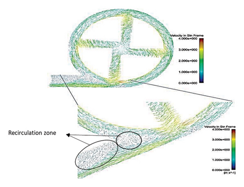
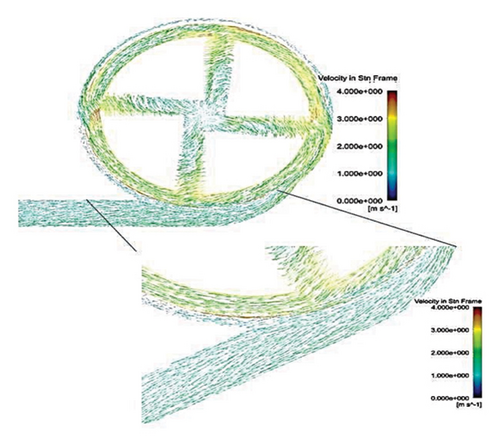
After the comparisons, it was observed that the volute chamber with a curved outlet performed better than the volute chamber with a tangential outlet. Finally, the volute chamber with a curved outlet was recognized as the appropriate geometry for the final designed pump.
3.2. Impeller
The performed simulations in this part are with the volute chamber selected in the previous step, i.e., the volute chamber with a curved outlet.
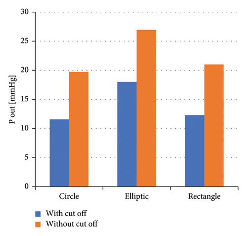
Due to the large number of models for simulation in this step, the simulation was performed at the design point (rotation speed of 1100 rpm and flow rate of 5 L/min), and the results were gathered (Figure 7).
3.2.1. Head
The constant 73.53 represents the conversion factor from head in meters to mmHg for blood.
Based on the simulation results of this research, impellers with an elliptical flow passage demonstrate superior performance in terms of produced head at the outlet, compared with circular and rectangular flow passages. The rectangular and circular flow passages rank second and third, respectively, in terms of head generation.
Regarding the presence of a cutout at the impeller’s outlet, across all three flow passages, impellers with a cutout generate less head at the outlet compared with those without a cutout.
3.2.2. Axial and Radial Force
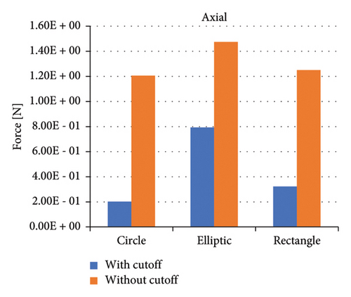
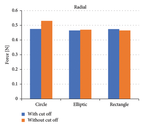
Figure 8 shows the axial forces for six impeller configurations, and Figure 9 shows the radial forces for six impeller configurations at a flow rate of 5 (L/min) and 1100 rpm. Impellers with an elliptical flow passage without cutouts bear the highest axial force among impellers. Impellers with a circular flow passage with cutouts bear the lowest axial force among impellers. In terms of the flow passage, the impellers with the elliptical flow passage bear a high axial force. Comparing impellers with cutouts and without cutouts showed that impellers with cutout bear less axial force. This difference in the forces is related to the direction of the velocity vectors at the channel’s exit, which is explained later.
3.2.3. Streamlines
Figure 10 illustrates the streamlines within different impeller designs, including circular, rectangular, and elliptical flow passages with and without cutouts. As observed, the flow irregularities in impellers with cutouts are more significant than those without. These irregularities are especially prominent at the channel’s beginning, indicating that flow disturbances are introduced early in the flow path and affect the overall flow distribution throughout the passage.
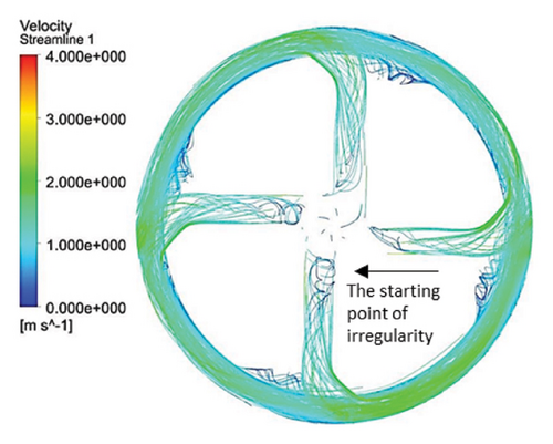
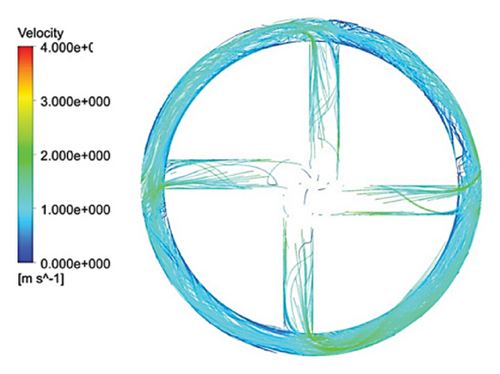
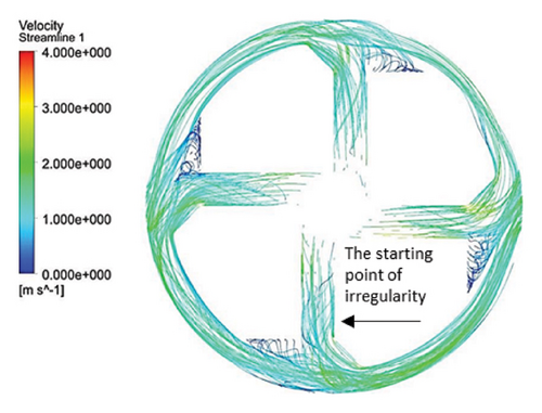
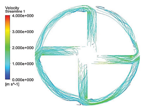
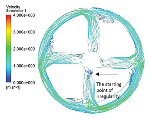
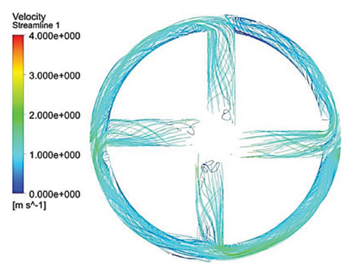
Impellers with circular flow passages exhibit the least amount of irregularity in streamlines compared with their elliptical and rectangular counterparts. This indicates that circular flow passages promote a more uniform and stable flow, reducing disturbances and maintaining a consistent velocity profile. In contrast, the elliptical flow passages show the highest level of irregularity within the channels, which highlights the complexity and potential inefficiency of this design in maintaining smooth flow patterns.
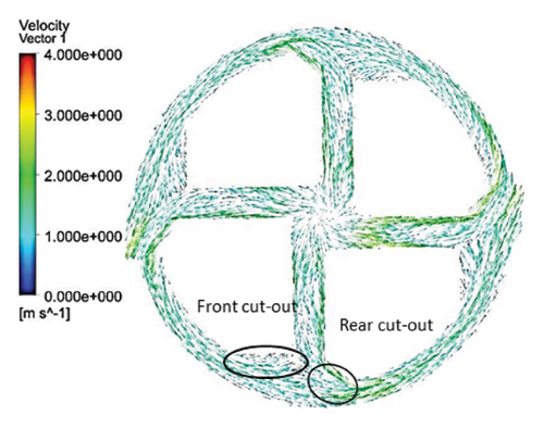
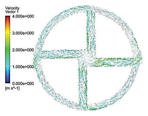
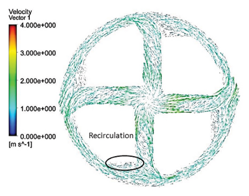
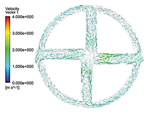
One key observation across all three flow passage designs is that impellers with cut-outs display severe irregularities, particularly at the front cutout region. This is likely due to the abrupt changes in flow direction and velocity introduced by the cutout. However, the rear cutout alleviates some of these irregularities at the channel outlet, potentially leading to smoother flow in the exit region. On the other hand, impellers without cutouts tend to exhibit recirculation flows at the outlet, which can reduce efficiency and increase energy losses, along with the risk of creating regions prone to thrombosis in applications like blood pumps.
3.2.4. Velocity Vectors
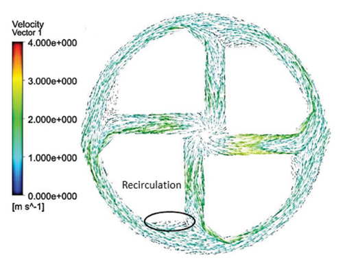
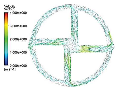
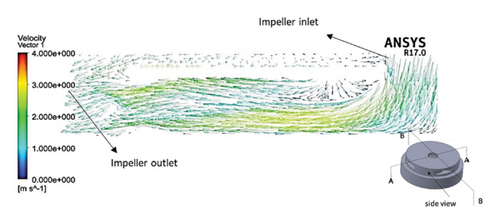
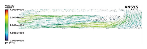
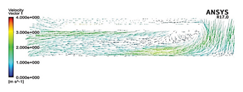
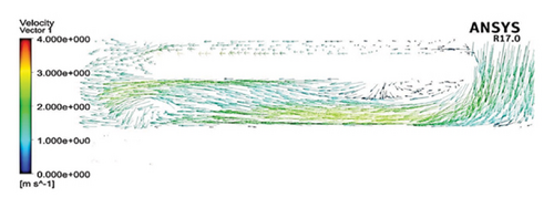
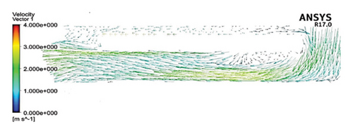
Figures 11 and 12 depict the velocity vectors for the different impeller designs, including rectangular, circular, and elliptical flow passages, with and without cutouts. Figure 12, in particular, provides a side view of the impeller’s flow patterns, showing how fluid enters and exits the impeller. This view allows us to observe how velocity changes occur along the impeller’s length, making it clear how different geometries and cutout designs impact flow behavior from inlet to outlet. Across all configurations, it is clear that recirculation flows are present in the impellers with cutouts, particularly at the front of the cutout and at the start of the channel. This recirculation could be caused by the sudden changes in flow direction and velocity as the fluid interacts with the sharp edges of the cutout. In the case of impellers without cutouts, recirculation flows are predominantly observed at the rear of the impeller’s outlet, where the fluid exits the impeller and enters the volute chamber. This can lead to inefficiencies, as the recirculating flow can cause energy loss and potential areas of stagnation. The elliptical flow passages display fewer recirculation zones than the rectangular and circular designs. This can be attributed to the greater horizontal length of the elliptical cross-section, which allows for more fluid contact with the volute chamber, enabling smoother passage through the impeller and quicker exit. The increased fluid contact reduces the opportunity for flow separation and recirculation, resulting in more efficient fluid movement. Another important observation is the impact of the cutout on the velocity field. As mentioned, changes in velocity are most noticeable toward the middle and end of the channel. In impellers with cutouts, these velocity changes occur closer to the outlet of the channel, near the impeller’s outlet. This suggests that the cutout primarily affects flow in the downstream region, possibly due to the abrupt transition caused by the cutout design. Conversely, in impellers without cutouts, the velocity changes are more concentrated in the middle of the channel, which indicates a more gradual flow disruption as the fluid moves through the passage.

3.2.5. Shear Stress
Figure 13 shows the shear stress distribution for six configurations. Comparing all three flow paths shows that the place of high shear stress for impellers with cutout is closer to the channel exit than for impellers without cutout. In other words, the cutout has postponed the place of high-shear stress. It was mentioned earlier in the section related to the velocity vectors that the changes in the velocity vectors in the impellers with cutouts are close to the outlet of the channel. In impellers with cutouts, the shear stress is lower in the front cutout than that in the rear cutout of the impeller. However, in impellers without cut out, the rear and front of the channel’s outlet have almost the same shear stress. Figure 14 illustrates the shear stress across different ranges, where at τ > 9 Pa the cleavage of von Willebrand factor occurs, at τ > 50 Pa platelet activation happens, and at τ > 150 Pa hemolysis takes place [35].
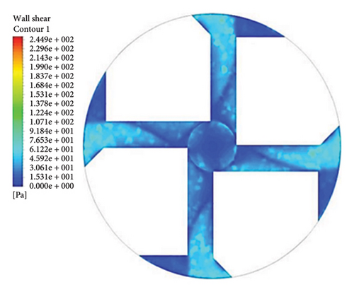
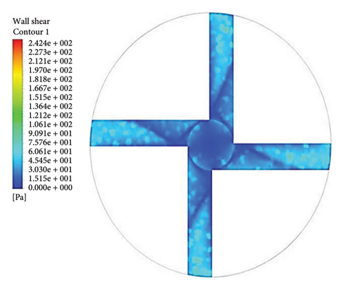
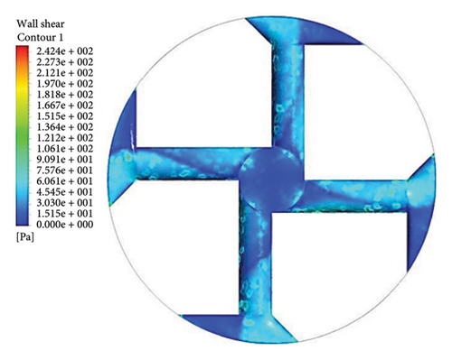
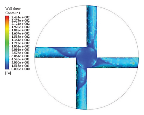
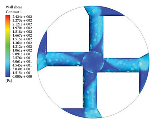
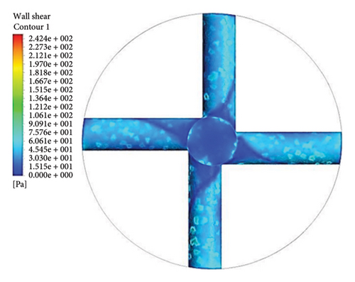

In the inlet part of the blade and at the outlet on the rear side of blades with cutouts, shear stresses less than the von Willebrand factor cleavage threshold are observed. In the other parts of the blade, the shear stress exceeds 9 Pa. In the front cutout of the blades, areas with shear stress above 50 Pa are seen, which are potential sites for platelet activation.
3.2.6. HI
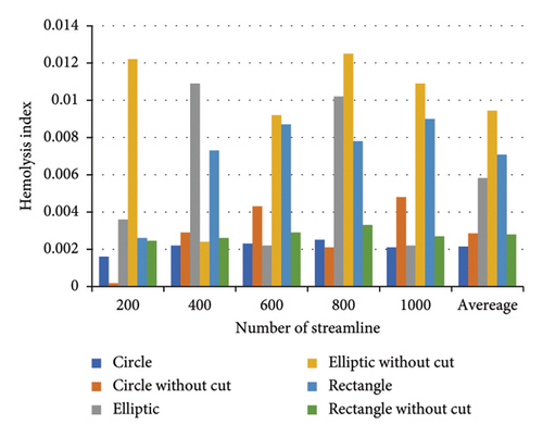
In this section, to ensure comprehensive coverage of the pump’s geometry, a higher number of streamlines was used to evaluate hemolysis more accurately. The more streamlines employed, the more thoroughly the flow paths within the pump are captured, leading to results that are closer to real-world conditions. However, increasing the number of streamlines introduces certain challenges. For example, some streamlines may pass through regions where the residence time of the fluid is erroneously extended, leading to potential distortions in the hemolysis results. In addition, increasing the number of streamlines significantly raises computational time.
To address these issues, we evaluated hemolysis using a range of streamline counts 200, 400, 600, 800, and 1000. This approach allowed us to strike a balance between accuracy and computational efficiency. In each step, the HI was calculated using the power-law model and Lagrangian method. Finally, the overall HI was obtained by averaging the hemolysis values across the different numbers of streamlines. This ensured that the results reflect both a sufficiently high number of streamlines while minimizing errors caused by artificially prolonged residence times in certain regions.
Figure 15 illustrates the HI for each configuration (circular, elliptical, and rectangular flow passages, with and without cutouts) relative to the number of streamlines. By averaging the hemolysis indices obtained from different streamline counts (200, 400, 600, 800, and 1000), the final HI becomes more balanced, providing a more consistent assessment of the hemolysis potential for each configuration.
3.3. Selection of the Optimal Configuration
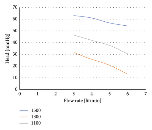
Finally, the selected configuration for the right ventricular assist pump with an impeller with a rectangular flow passage without cutout was simulated for different rotational speeds and flow rates. Its hydraulic performance diagram is shown in Figure 16.
4. Discussion
This study demonstrated that the volute chamber with a curved outlet significantly reduces the occurrence of recirculation flows compared with the volute chamber with a tangential outlet. Recirculation zones, characterized by reverse or swirling fluid motion, lead to increased residence times. These zones are problematic in blood pumps because they can create stagnant flow regions, promote platelet activation, and ultimately increase the risk of thrombosis. The smoother and more uniform flow in the curved outlet design minimizes these undesirable recirculation areas and enhances hemodynamic performance.
It is important to clarify that while “regular streamlines and velocity vectors” refer to the orderly and consistent motion of fluid particles along predictable paths, “areas prone to recirculation flows” indicate zones where the flow reverses or vortices form. In the case of the curved outlet, the regularity of the streamlines and velocity vectors means that the blood follows a clear and steady path, reducing the likelihood of flow disturbances. In contrast, recirculation zones are characterized by chaotic and irregular flow patterns, which can trap blood and cause increased residence times, leading to potential clot formation. The design of the curved outlet effectively suppresses these recirculation areas, leading to improved hemodynamic performance. Our findings are consistent with previous studies. For example, Li et al. [55] examined the impact of volute design features on the hemodynamic performance and hemocompatibility of centrifugal blood pumps used in ECMO. They demonstrated that optimizing the volute design to achieve more regular flow patterns and reduce recirculation areas significantly decreases the risk of thrombosis.
The volute chamber with a curved outlet has a lower HI than the volute chamber with a tangential outlet. Therefore, it was selected as the suitable volute chamber for the final pump. Fu et al. [56] showed that volute chambers with more regular flow patterns and reduced recirculation areas significantly decrease thrombosis risk, supporting the advantages of the curved outlet design.
In the second phase of the study, we investigated the effect of the impeller’s flow passage cross-section and the presence or absence of a cutout at the impeller’s outlet. The impeller with an elliptical flow passage exhibited superior hydraulic performance compared with the rectangular and circular passages, which ranked second and third, respectively. However, the presence of a cutout in all three flow passages reduced hydraulic performance. This reduction is due to the decreased energizing area for the fluid; impellers without cutouts have a larger energy transfer area because the rear cutout reduces the energy transfer area. Therefore, impellers without cutouts appear more suitable for optimal hydraulic performance.
When examining axial forces, the impeller with an elliptical cross-section experienced higher axial forces than other designs, whereas the presence of a cutout effectively reduced these forces. Detailed velocity vector analysis revealed that, in impellers with a cutout, the velocity vectors at the impeller’s outlet (cut area) are directed downward, while in impellers without a cutout, these vectors are radial or slightly upward. The difference in axial forces between impellers with and without a cutout is attributed to this directional variation in velocity vectors. These findings align with those of Nishida et al. [52], who, in their study of impeller geometry and its impact on lift-off characteristics and rotational attitude in a centrifugal blood pump, also concluded that a cutout in the impeller design significantly reduces axial forces and prevents unintended lift-off of the impeller.
Examination of radial forces indicated that the flow passage shape and the presence or absence of a cutout at the outlet have little effect on the magnitude of radial forces. Therefore, these forces primarily impact the design and selection of bearings rather than the impeller design.
Streamline analysis revealed that the presence of a cutout contributes to flow irregularities at the entrance of the channel. In the absence of a cutout, the streamlines at the channel’s entrance are more regular, resulting in a more stable flow. The impeller’s front cutout creates recirculation flows at the channel’s entrance, which can cause thrombosis. All six configurations studied exhibited recirculation flows at this location. To reduce the recirculation amount, modifications such as curving the corner of the channel and increasing the diameter of the suction tube at the blade inlet can be implemented. Adding a rear cutout to the impeller improves flow movement in the outlet section and reduces recirculation flows in the rear part of the impeller outlet.
Assessment of blood hemolysis across different impeller designs revealed that the impeller with a rectangular flow passage without a cutout had the lowest blood HI. Although the impeller with the elliptical flow passage showed better hydraulic performance, it exhibited a high blood HI, indicating a trade-off between hydraulic efficiency and hemocompatibility. Results demonstrated that optimizing the volute chamber shape and impeller design can lead to more efficient and safer blood pumps.
4.1. Innovations in Sustainable Materials and Advanced Fluid Systems for Blood Pump Technology
Recent advancements in sustainable materials and fluid dynamics offer new ways to improve the efficiency and design of blood pumps. Ecofriendly materials, essential for creating durable and biocompatible devices, can endure the challenging conditions of blood flow, ensuring patient safety and supporting global sustainability goals [57, 58]. Nanotechnology advancements, particularly with nanozymes, are also promising in reducing blood cell damage, friction, and improving the durability of blood pumps [59].
In fluid dynamics, managing turbulent flow and shear stress is critical to maintaining blood cell integrity and pump efficiency. Insights from broader fluid system research contribute to effective turbulence modeling and flow optimization, enhancing pump energy efficiency and durability [60]. Integrating sustainable materials and advanced fluid dynamics thus offers enhanced performance, safety, and longevity for blood pumps, aligning with global sustainability and healthcare objectives.
5. Conclusion
-
Volute chamber design: selecting a volute chamber with a curved outlet effectively reduces recirculation flows, thereby decreasing the risk of thrombosis and hemolysis. This design choice makes it the preferred option for the final blood pump configuration to enhance safety and efficiency.
-
Optimal impeller: the rectangular flow passage impeller without a cutout was determined to be the optimal design for reducing blood damage. Despite its slightly lower hydraulic performance compared with the elliptical design, this impeller achieved a lower HI (0.0028), indicating reduced blood cell damage. While the impeller with an elliptical flow passage demonstrated superior hydraulic performance, its higher HI suggests that further design adjustments, such as lowering rotational speed or other modifications, are necessary to improve its blood compatibility.
-
Impact of cutouts: the presence of a cutout in the impeller creates flow irregularities at the channel entrance, while the impeller without a cutout promotes a more regular flow within the channel and improves performance. In addition, adding a rear cutout to the impeller reduces recirculation flows at the blade outlet. The cutout at the end of the impeller helps in reducing axial forces.
Nomenclature
-
- BIVAD
-
- Biventricular assist device
-
- Hb
-
- Hemoglobin
-
- HI
-
- Hemolysis Index
-
- HTC
-
- Blood pump
-
- LVAD
-
- Left ventricular assist device
-
- MREA
-
- Blood pump
-
- Re
-
- Reynolds number
-
- RVAD
-
- Right ventricular assist device
-
- TAH
-
- Total artificial heart
-
- VAD
-
- Ventricular assist device
-
- RBC
-
- Red blood cell
-
- k-ω SST
-
- Turbulence model
-
- RVF
-
- Right ventricular failure
-
- PIV
-
- Particle image velocimetry
-
- MRF
-
- Multiframe reference
-
- F (Fx, Fy, Fz)
-
- Force (force in the x-direction, y-direction, and z-direction)
-
- FDA
-
- Food and Drug Administration
-
- Q
-
- Flow rate
-
- Δt
-
- Residence time
-
- U
-
- Velocity
-
- D
-
- Impeller diameter
-
- P
-
- Pressure
-
- ρ
-
- Density
-
- μ
-
- Dynamic viscosity
-
- ν
-
- Kinematic viscosity
-
- τ
-
- Shear stress
-
- g
-
- Gravity constant
-
- R
-
- Radius
-
- H
-
- Head
-
- σ
-
- Stress tensor
-
- Aimp
-
- Impeller surface area
-
- ω
-
- Angular velocity
-
- n (nx, ny, nz)
-
- Normal vector (in the x-direction, y-direction, and z-direction)
Conflicts of Interest
The authors declare no conflicts of interest.
Funding
This research was partially supported by the Iran National Science Foundation (INSF) under project no. 99016799.
Open Research
Data Availability Statement
The data supporting the findings of this study are available from Professor Niroomand, but there are limitations to the availability of these data, which were used for the current study under license, and are therefore not publicly available. However, the data are available from the authors upon reasonable request and with the permission of Professor Niroomand.


