Assessment of Life Extension of Hydrodrives of Aircraft Using Wear Analysis
Abstract
This study evaluates the wear characteristics of flat slide valve material in contact with distributive bush material under varying loading conditions using a pin-on-disc apparatus. Given the critical role of hydrodrives in aircraft safety and performance, understanding material wear behavior is essential for enhancing component longevity and operational efficiency. The study assesses key tribological parameters, including the coefficient of friction, wear rate, and mass loss. Experimental results show that at a normal load of 22.5 kg, the material mass loss for linear displacements corresponding to 1975 and 2500 flight hours is 2.25 mg and 3.37 mg, respectively. The maximum coefficient of friction recorded was 0.071 at a normal load of 20 kg. These findings demonstrate that the wear resistance of the tested materials supports the extension of hydrodrive operational life beyond 2500 flight hours, reducing maintenance requirements and enhancing aircraft system reliability. The insights gained from this research provide a foundation for improving the durability of critical aircraft components, ultimately contributing to safer and more efficient aviation systems.
1. Introduction
The hydrodrive system in aircraft significantly enhances control, manoeuvrability, and safety by supplying precise and reliable hydraulic power to essential control surfaces, including ailerons, elevators, rudder, flaps, slats, and landing gear systems [1]. It ensures smooth, responsive operation during regular flight manoeuvres, thereby improving aircraft handling and performance, while also serving as a critical backup during hydraulic system failures, allowing pilots to maintain control and safely execute emergency procedures [2]. Extending hydro drive operational life beyond 2500 flight hours minimizes component wear, reduces maintenance intervals, and boosts reliability and operational efficiency, thus lowering downtime and operational costs [3]. Essential components such as the flat slide valve, which controls fluid flow and pressure distribution, and its mating surface, the distributive bush, directly interact under operational conditions to ensure smooth, efficient performance [2]. Improving wear resistance of these components is crucial, as excessive wear under various load, lubrication, material, and hardness conditions can cause internal leakage, reduced volumetric efficiency, and diminished system performance. Practical experiments using pin-and-disc apparatuses often utilize “equivalent” materials due to manufacturing limitations, availability constraints, or geometric complexities of actual components. These carefully selected equivalents with similar hardness, composition, and tribological properties ensure accurate simulation of wear behavior under realistic operational conditions, providing representative experimental results closely correlated with actual hydrodrive service conditions. Such technical advancements not only bolster aircraft safety and reliability but also align with industry-wide objectives for more sustainable, reliable, and cost-effective aviation solutions.
Cao and Dai [4] developed a performance degradation model for hydraulic actuators in excavators, accurately forecasting performance degradation and estimating useful life of components like seals. Their research showcases practical piston responses at various wear stages. Tonelli et al. [5] examined methods to enhance wear resistance of steel components in hydraulic actuators subjected to sliding motion. Through dry sliding tests, they evaluated alternative coatings such as air plasma sprayed and C:H DLC coatings, ranking them based on performance. Nuruzzaman and Chowdhury [6] studied friction coefficients of aluminium sliding against copper, brass, and aluminium pins using a pin-on-disc apparatus, varying load, velocity, and humidity to observe friction changes. Nomula et al. [7] investigated flow distribution characteristics of port plate pairs in seawater hydraulic motors, developing models and performing simulations to assess effects of water film, inlet pressure, and rotation speed on leakage flow. Kang et al. [8] created CoCrNi/W/Agx composites with superior wear resistance in ambient air and vacuum conditions. These composites significantly improved tribological performance compared to CoCrNi alloy. Li et al. [9] analyzed contact sliding between metal sheets and dies under high stresses in deep drawing processes, assessing friction, surface morphology, and wear behavior based on tool and workpiece properties. Zhang et al. [10] tested friction properties of various pin materials combined with Cr3C2 or Al2O3 coatings, finding the C/C composite-Cr3C2 pairing superior due to lower friction and wear. Sosa et al. [11] compared tribological characteristics of sintered gear materials and standard materials, noting RS pins showed superior friction and wear resistance due to their hardness and compacted structure. Sharma and Sharma [12] measured friction and wear properties using aluminium discs and high-speed steel pins. They identified a significant wear transition at 15-kg load. Recent studies by Hao et al. [13], Li et al. [14], and Zuo et al. [15] introduced advanced lubrication techniques, durable nanoparticles, and surface designs to enhance wear resistance and delay transitions. Zhang et al. [16] examined turbulence and cavitation effects on water-lubricated journal bearings, observing significant impacts on static characteristics and minimum film thickness. Verma et al. [17] achieved friction reduction and low wear volume with nanohybrid lubricants. Houpert and Menck [18] detailed bearing life models, determining oscillation factors numerically based on operational parameters. Center [19] evaluated gear pump degradation due to wear particles and test dust, showing significant differences in operational duration based on cleanliness levels. NOvak et al. [20] demonstrated reduced friction and wear using heterogeneous gradient nanostructures under dry sliding tests. Wu et al. [21] studied mechanical and wear properties of titanium-alloyed high-strength steels, concluding excessive titanium precipitates adversely affected mechanical performance.
Prediction and enhancement of hydrodrive life on the basis of aircraft-simulated conditions using wear analysis is a novel approach and is useful for the aviation industry. Despite numerous existing research studies, investigations specifically targeting life prediction and enhancement of hydrodrives based on wear analysis remain scarce. As a proven technique, the pin-on-disc method effectively simulates and assesses wear behaviors of mating metallic surfaces, directly contributing valuable data for assigning reliable life estimates to these critical components. Therefore, this method provides significant clues for assigning reliable life estimates and enhancing hydrodrive lifespan. In particular, this work is the first to experimentally investigate the wear behavior aimed explicitly at predicting and extending the operational life of hydraulic-actuated drives used in the flash module under realistic, flight-like conditions. Although specific studies have targeted individual tribological parameters as mentioned previously, this study uniquely addresses comprehensive wear-based life prediction for hydrodrives, directly contributing to advancements in aviation reliability and safety.
2. Material and Methods
2.1. Experimental Setup
The pin-on-disc apparatus (Figure 1) evaluates the tribological behavior of flat slide valves and distributive bushes in hydrodrives. Designed to apply loads up to 200 N and rotational speeds between 200 and 2000 rpm, the apparatus allows friction and wear studies between a stationary pin and rotating disc (Figure 2). Adjustable test parameters include normal load, rotational speed, and wear track diameter. Electronic sensors record tangential frictional force and wear, displaying results as functions of load and speed. The robust structure absorbs testing forces and minimizes vibrations, supported by four adjustable antivibration pads that level the apparatus. Internal components like the AC motor, drives, and electronics are enclosed within the panel-covered structure, featuring an emergency stop switch on the front panel. The spindle, driven by an AC motor through a timer belt for reduced vibration, is mounted on taper roller bearings within a rigid housing attached firmly to the base plate. A holder secures the wear disc to the spindle top.
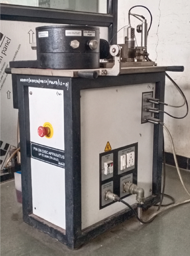
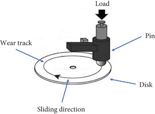
Load application occurs via a balanced loading lever, with a specimen holder on the one end and a suspended weight system on the other. The 1:1 pivot design ensures equal loading and precise friction measurement through a strain gauge load cell mounted opposite the specimen. Wear is measured by a linear variable differential transducer (LVDT) mounted symmetrically relative to the pivot, capturing vertical plunger movements corresponding to wear. The LVDT, with the least count of 1 μm, measures wear within ±2 mm, accommodating positive and negative readings. Frictional force is measured by a beam-type load cell (capacity up to 200 N), fixed on the sliding plate to align with varying wear track diameters. This load cell, constructed from corrosion-resistant superalloy steel, incorporates strain gauges forming a Wheatstone bridge for precise measurement of minor deformations caused by frictional forces. Rotational speed measurement employs an inductive proximity sensor mounted perpendicular to an indexing disc with peripheral slots, providing contactless detection free from mechanical wear. As the sensor disc rotates, the sensor’s oscillator circuit amplitude shifts, generating digital signals for accurate RPM measurement.
Note that experiments were repeated three times for each test condition, enhancing data reliability, consistency, and statistical validity. This repetition reduces experimental errors and ensures that findings are robust and representative. Test conditions mirrored realistic aircraft hydrodrive scenarios, with a 20-kg load reflecting average in-flight ground load and a 0.5 m/s sliding velocity consistent with hydraulic actuator displacement speeds. These parameters, derived from flight data recorders (FDRs) and hydrodrive manuals, reinforce the practical relevance of experimental outcomes.
2.2. Sample Preparation
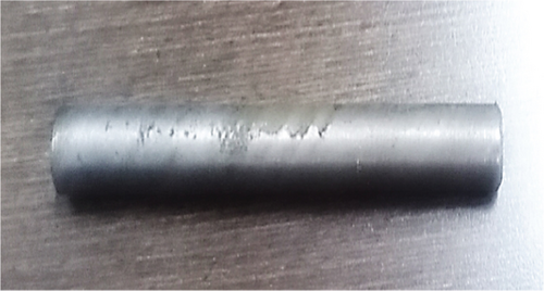
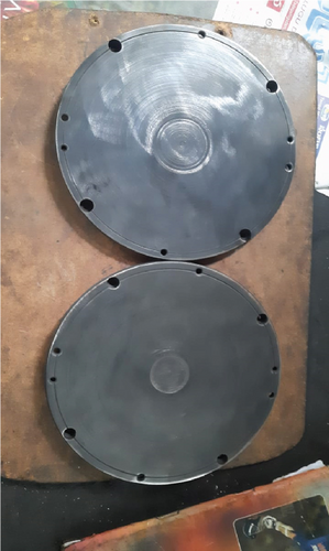
The aim of this study was to predict the life expectancy of hydrodrives utilizing a pin-on-disc apparatus. By examining the wear behavior of the interacting materials, essential insights regarding their durability and performance under practical conditions can be obtained. Consistent with the experimental procedure outlined, the pin and disc components should be constructed from materials possessing specific hardness characteristics. To identify appropriate materials, tests were performed to evaluate the composition and hardness of the flat slide valve and distributive bush materials. The hardness measurements revealed that the flat slide valve material exhibited a hardness value of 474 HV, categorizing it as a comparatively softer material. In contrast, the distributive bush material demonstrated a higher hardness value of 684 HV, indicating it to be significantly harder. Based on these results, it was determined that the pin in the experimental apparatus should be fabricated from a material equivalent to that of the flat slide valve, representing the softer component. Conversely, the disc should be made from a material equivalent to the distributive bush, representing the harder component. This deliberate material selection ensures that the pin and disc accurately mimic the mechanical characteristics of their respective counterparts in the hydrodrive system, resulting in reliable and representative experimental outcomes. The specific material specimens used in the experimental setup, corresponding to the pin and disc components, are illustrated in Figures 3 and 4, respectively. These figures provide clear visual representations of the specimens derived from the flat slide valve and distributive bush materials, as previously identified. By presenting these physical specimens, the figures enhance understanding of the selected materials, their distinctive characteristics, and their roles within the scope of this experimental investigation.
3. Experimental Procedure
3.1. Establishment of Experimental Conditions
Experimental conditions have been established based on data obtained from the standard hydrodrive workbench manual [22]. The following parameters are used for experimentation.
3.1.1. Flat Slide Valve
- a.
Radius (R): 25 mm (the maximum distance from the pivot point to the edge of the slide valve).
- b.
Maximum included angle (θ): 30°. Although the measured angle of the slide valve’s actual movement is 19°, an angle of 30° has been adopted for calculations to incorporate a factor of safety of 1.5.
- c.
Rotation frequency (N): 209 rotations/h. This value corresponds to the highest operational frequency recorded during a flight test on the standard hydrodrive workbench, as referenced in [22].
3.2. Data Processing
3.3. Calculation of Linear Velocity
3.4. Normal Load Calculation
- a.
Spring compression effort: 4.2 ± 0.3 kg
- b.
Number of springs: 5
- c.
Total maximum normal load exerted by 5 springs: 4.5 kg × 5 = 22.5 kg
Therefore, the actual maximum normal load acting on the flat slide valve of the hydrodrive is 22.5 kg. However, the experimental setup allows a maximum load of only 20.38 kg (200 N) to be applied on the pin. Consequently, during experimental trials, a maximum pin load of 20 kg is used. The mass loss corresponding to the 22.5 kg load is extrapolated from data obtained at incremental loads of 5 kg, 10 kg, 15 kg, and 20 kg.
3.5. Calculation of Mass Loss for Sliding Area of Flat Slide Valve
The proportionate mass loss of the flat slide valve, with a sliding area of 2.5 cm2, is calculated based on the experimentally determined mass loss for the pin with a sliding area of 0.78 cm2. Detailed experimental results, along with their physical interpretations, are provided in the following section. The same experimental method was applied to determine the linear displacement, sliding velocity, and mass loss equivalent to 2500 flight hours. Experiments were conducted under varying normal loads, and the outcomes are discussed comprehensively in the subsequent section.
4. Results and Discussion
Experimental trials were conducted to evaluate the coefficient of friction, wear, and mass loss of flat slide valve materials using a pin-on-disc apparatus under laboratory conditions in a wet environment. The lubricating oil used was identical to that applied to the flat slide valve and distributive bush within the aircraft’s hydrodrive system. All tests were performed under ambient conditions. Trials involved applying various normal loads (5 kg, 10 kg, 15 kg, and 20 kg) on the pin, with a maximum limit of 20 kg due to the apparatus’s load capacity constraints. Two linear displacements, corresponding to operational durations of 1975 and 2500 flight hours, were analyzed. The sliding velocity and disc speed, utilizing a disc made from distributive bush material, were determined based on these linear displacements. A sliding velocity of 0.5 m/s at a disc speed of 195 rpm was selected for detailed analysis. Other sliding velocities corresponding to disc speeds of 95 rpm and 190 rpm (also resulting in a sliding velocity of 0.5 m/s but at different track radii) were investigated. However, since the results from these variations showed no significant differences, subsequent discussions are limited to the results obtained at a sliding velocity of 0.5 m/s and 195 rpm.
4.1. Measurement of Coefficient of Friction
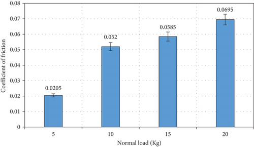
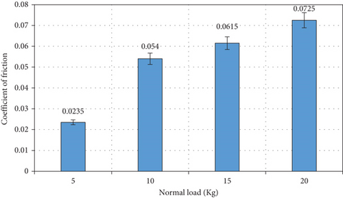
The coefficient of friction is defined as the ratio of the frictional load to the normal load and is dimensionless. To investigate this, the coefficient of friction for flat slide valve materials was experimentally measured at varying normal loads—specifically 5 kg, 10 kg, 15 kg, and 20 kg—for two distinct samples. The results for these two samples, along with their averaged values at each normal load, are presented in Figures 5 and 6. Analysis of the experimental data reveals a clear trend of increasing coefficient of friction with rising normal load. This increase can be explained by enhanced adhesion strength between the mating surfaces. Under lower load conditions, many metallic pairs exhibit reduced friction due to the formation of oxide films that separate the surfaces, preventing direct metal-to-metal contact. However, higher loads disrupt these oxide layers, promoting direct metallic contact and consequently increasing frictional values. At the maximum applied load of 20 kg, the highest recorded coefficient of friction is 0.071, which remains below the critical threshold of 0.1. Therefore, the materials tested for the flat slide valve and distributive bush can be classified as “lubricous materials.” Additionally, experimental observations showed a significant drop in friction upon establishment of a lubricating oil film between the contacting surfaces. This underscores the effectiveness of lubrication in reducing friction under the tested conditions.
4.2. Measurement of Wear
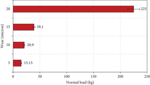
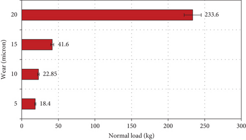
The wear (measured in microns) of flat slide valve material was assessed across varying normal loads, as depicted in Figures 7 and 8. Results demonstrate a clear correlation between increasing normal load and material wear. Up to a load of 15 kg, wear increases gradually, but beyond this load, wear sharply escalates, reaching a maximum average of approximately 230 microns at 20 kg. This rapid increase in wear at higher loads is primarily attributed to the drastic thinning of the lubricating oil film, resulting in direct metallic contact. Specifically, a critical tipping point at 15-kg load was identified, beyond which wear accelerates significantly. Recognizing this transition point is crucial for designing flat slide valves, as it represents a functional limit beyond which performance deteriorates rapidly. Addressing this accelerated wear under high-load conditions is vital for ensuring the reliability and longevity of hydrodrive systems. Potential solutions include advanced material selections or innovative design modifications. For instance, applying surface treatments or coatings, as demonstrated by Tonelli et al. [5], can substantially enhance wear resistance. Their findings showed significant wear improvements through the application of air plasma-sprayed and C:H DLC coatings under high sliding loads. Moreover, exploring alternative wear-resistant materials, such as composites or alloys with superior wear properties (e.g., CoCrNi/W/Ag composites), might offer promising solutions. Additionally, refining the geometry of sliding components to facilitate even load and stress distribution can help preserve the lubricating film integrity, thus delaying wear escalation. In summary, these study insights, corroborated by relevant literature, provide valuable guidance on new strategies to significantly enhance durability and performance in hydrodrive systems operating under demanding load conditions.
4.3. Measurement of Material Mass Loss
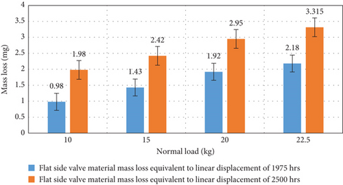
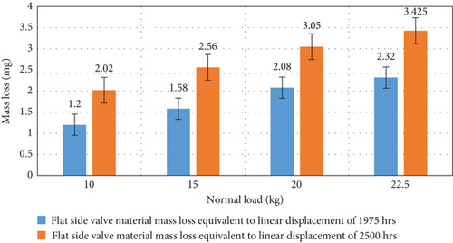
The mass loss of the flat slide valve material was evaluated by comparing the pin’s mass before and after each experimental trial under varying normal load conditions. Test durations corresponding to 1975 and 2500 flight hours were 181 and 229 min, respectively, maintaining a sliding velocity of 0.5 m/s at a rotational speed of 190 rpm. Figures 9 and 10 illustrate the experimental results showing material mass loss due to friction and wear. Results indicated that the material mass loss increases with higher normal loads. Experimental trials were limited to a maximum normal load of 20 kg, constrained by the testing setup’s capacity. However, in actual aviation applications, the flat slide valve typically experiences a maximum spring load of 22.5 kg. Consequently, extrapolation methods were employed to estimate the material mass loss at this higher load. Through extrapolation, the average estimated mass loss at a normal load of 22.5 kg for linear displacements equivalent to 1975 and 2500 flight hours was found to be 2.25 mg and 3.37 mg, respectively. This indicates an additional mass loss of 1.12 mg (3.37 minus 2.25 mg) over an incremental flight duration of 525 h (2500 minus 1975 hrs), which is considered negligible.
4.4. Measurement of Volume Loss
The density of the pin material (13KH11N2V2M), as referenced from manual [22], is 7426 kg/m3. Using the previously calculated mass loss of 1.125 mg over the extended operating duration (from 1975 to 2500 h), the corresponding volume loss is approximately 0.000151 cm3. Given that the slide valve has a surface area of around 2.5 cm2 and a total volume of about 1 cm3, the observed volume loss of 0.000151 cm3 represents an extremely minor fraction relative to the component’s total volume.
4.5. Running-in of Hydrodrive on Test Stand
To validate the study, standardized workbench trials were conducted on a hydrodrive test stand, which had already completed 1972 h of operation. Mass loss for the flat slide valve and distributive bush was measured at regular intervals of 100 h over an additional 600 flight hours, bringing the total operation to 2572 h. After these 600 h of equivalent flight operation, a material mass loss of 0.6 mg was observed in the flat slide valve. In contrast, the pin-on-disc apparatus recorded a higher material mass loss of approximately 1.125 mg after 525 flight hours. The discrepancy in these measurements can be attributed to the more rigorous test conditions employed in the pin-on-disc experiments. However, both methodologies indicated minimal material mass loss, and their results were consistent. These experimental and operational trials underline the continued reliable performance of the hydrodrive for durations up to and potentially beyond 2500 h, contingent upon the sustained effective operation of the flat slide valve and distributive bush. Consequently, the findings from this laboratory research suggest significant potential for safely extending the operational life of various hydrodrive systems used in aircraft to at least 2500 flight hours.
The friction coefficient and wear trends identified in this study align closely with previous research findings [4, 8, 9], which emphasize the effectiveness of lubrication films in reducing wear. The observed minimal mass loss of 3.37 mg over 2500 h in this study is considerably lower than wear rates documented in studies such as [20]. This reduction in wear can be attributed to the specific material composition of the flat slide valve and distributive bush, as well as the distinct geometry used in the experiments. Furthermore, real-time validation through running-in trials, a critical yet often overlooked aspect in similar studies, has provided practical confirmation of experimental results, thereby reinforcing the reliability of the experimental approach and the durability of the materials tested. These wear patterns are consistent with established tribological principles. Under light loads, a robust lubricating oil film effectively prevents metal-to-metal contact, thereby minimizing wear. However, as the load exceeds 15 kg, the thickness of the lubricating oil film diminishes, eventually causing direct metallic contact. This leads to adhesive wear, characterized by material transfer and surface degradation. The rapid increase in wear under higher loads corresponds with the failure of boundary lubrication, a well-documented phenomenon extensively discussed in tribological research.
5. Conclusions
- •
The coefficient of friction at a normal load of 20 kg was determined to be 0.071 (average), which is below the critical threshold of 0.1, classifying the materials as lubricous and suitable for low-wear applications.
- •
The maximum wear observed was approximately 230 microns (average) at a normal load of 20 kg, indicating minimal material degradation over prolonged operation.
- •
Average material mass loss was calculated as 2.25 mg and 3.375 mg for flight hours of 1975 and 2500, respectively, at a normal load of 22.5 kg. An additional average material mass loss of only 1.125 mg was observed for 525 flight hours, demonstrating wear stability over extended service life.
- •
The running-in trial between 1972 and 2572 flight hours revealed no degradation in testing parameters, reinforcing the long-term durability and reliability of hydrodrives for up to 2500 flight hours.
- •
The findings confirm that the wear resistance and durability of the flat slide valve and distributive bush materials can extend the hydrodrive operational life up to 2500 h without significant performance degradation, thereby improving the reliability and efficiency of aircraft hydraulic systems.
By reducing friction and minimizing wear-induced failures, the tested materials enhance operational lifetime, reduce maintenance, and improve safety in aerospace applications. However, some limitations exist. The maximum tested load (20 kg) was slightly below the operational load (22.5 kg), introducing minor extrapolations and uncertainties. Experiments were conducted under controlled conditions, which may not fully reflect real-world variables like temperature fluctuations or contamination. The pin-on-disc wear analysis may not perfectly replicate actual hydrodrive sliding conditions. Future research should focus on higher load testing, real-world environmental factors, refined wear analysis, long-term field studies, and advanced material characterization to optimize hydrodrive reliability in the aircraft.
Nomenclature
-
- R
-
- radius of the flat slide valve (mm)
-
- θ
-
- maximum included angle (°)
-
- N
-
- rotation frequency of the flat slide valve (rotations/hour)
-
- S
-
- linear displacement (m)
-
- H
-
- total operating time (hours)
-
- HV
-
- Vickers hardness
-
- LVDT
-
- linear variable differential transducer
-
- RPM
-
- rotations per minute
-
- FDR
-
- flight data recorders
Ethics Statement
The authors have nothing to report.
Consent
The authors have nothing to report.
Disclosure
All authors have given their consent for the publication of this manuscript.
Conflicts of Interest
The authors declare no conflicts of interest.
Author Contributions
S.S., A.K., and S.P. conceptualized and designed the study. S.S. and A.K. contributed to data collection and analysis. S.S. and B.S. assisted in manuscript drafting and critical revisions. B.S. and A.B. supervised the project, provided guidance, and finalized the manuscript. All authors reviewed and approved the final version of the manuscript.
Funding
The authors received no specific funding for this work.
Open Research
Data Availability Statement
The data that support the findings of this study are available from the corresponding author upon reasonable request.


