Multifunctional Metasurface Design via Physics-Simplified Machine Learning
Abstract
Metasurface can manipulate electromagnetic (EM) waves flexibly, which provides the basis for functional integration. Recently, the efficient machine-learning-assisted methods have attracted intensive attentions in multifunctional metasurfaces design. However, the conventional machine-learning-assisted metasurfaces design is to fit the internal relationship in the form of black box, which ignores the underlying physical logic, resulting in the increased complexity of machine learning architecture with the parameters increasing. In order to adapt to the multiparameter optimization in multifunctional metasurfaces design, we propose a multiplexing neural network (MNN) based on decoupling at the physical layer to simplify both the structural parameters and the network architecture. The four interacting parameters are simplified into four independently regulated parameters so that the facile design of four functions can be realized only by multiplexing a simple neural network. For verification, four functions of scattering, anomalous reflection, focusing, and hologram are integrated in the same metasurface aperture by MNN. Performances of the metasurface are fully demonstrated by simulation and measurement. Importantly, this work paves the way for the bidirectional simplification of machine learning and metasurface design via physical inspiration, which provides an integrated design method of multifunctional metasurfaces and can be potentially applied to satellite communications and other fields.
1. Introduction
With data storage capacity increasing, as well as information processing speed, in information communication system, electromagnetic (EM) integration plays an increasingly important role in the trend of multiscenario application of equipment [1]. Metasurfaces, consisting of periodic or quasiperiodic microstructures, can be characterized by effective and homogenized surface material parameters, which can engineer the properties of EM waves [2]. Metasurfaces not only customize the equivalent EM parameters at will but also provide a design approach from function to structure. Especially, the elaborate structures, together with the ingenious arrangement, significantly promote powerful ability of metasurfaces to control EM waves [3]. Customizing the metasurfaces in detail, including microstructures and arrangement, the modulation freedom of EM characteristics such as amplitude [4, 5], phase [6, 7], polarization [8, 9], and wavefront [10–12] can be further improved. Therefore, the fascinating wave-manipulation capabilities of metasurfaces have been widely applied in perfect absorption [13], anomalous deflection [14], polarization conversion [15], and wavefront control [16], which exhibits further advantages in applications compared with their conventional counterparts.
Especially, different from traditional phase modulation generated by EM waves propagating in the medium, metasurfaces mainly rely on resonance to abruptly change phase across the interface, which can minimize the bulk size and high cost [17]. The phase modulation of metasurfaces such as resonance phase [18, 19], Pancharatnam–Berry (PB) phase [20, 21], propagation phase [22, 23], and detour phase [24, 25] can modulate the phase response by changing the medium size, geometric position, medium thickness, and relative position, respectively. With versatile mechanisms of phase modulation, metasurfaces present many charming performances in beam scattering [26], dispersion engineering [27], vortex beams [28], and holography [29]. The diverse theories of phase modulation lay the foundation for functional integration. The multifunctional integration can be tailored by angular momentum multiplexing [30, 31], polarization multiplexing [32, 33], wavelength multiplexing [34, 35], and angle multiplexing [36, 37]. Also, the reconfigure metasurfaces that can switch among different scenarios can be regarded as time multiplexing [38–40]. However, the improvement of functional integration means the increase of design complexity of metasurface, which undoubtedly causes the difficulty of metasurface design.
Fortunately, machine-learning-aided design provides convenience for functional metasurfaces design rapidly, which enables accurate prediction of geometrical parameters and EM responses [41, 42]. Forward design that predicts EM response from structure can be applied to substitute full-wave simulation [43–47]. Conversely, inverse design that calculates geometrical parameters from EM response can fast design metasurfaces without sweeping parameters [48–51]. With the rapid development of machine learning methods, multilayer perceptron networks, generative adversarial networks, and variational autoencoder networks have been widely used in metamaterial design [52, 53]. Machine learning-assisted metamaterial design proposed a novel approach for accelerating metamaterial design, which can be further applied in fast design of multifunction integration and bandwidth expansion [54–56]. Both the forward design and inverse design of machine learning assistance effectively extend the functional design of metasurfaces. However, the dimension of structural design is greatly increased, thus confusing machine learning application. In the design of machine learning, data and architecture are the key factors in determining the effectiveness of machine learning training. Therefore, the optimization of data and architecture can simplify network framework. One optimization approach is physics-inspired machine learning. On the one hand, the new architectures of network, such as kernel function and prior conditions, are immitted according to the physical principle [57–59]. On the other hand, the network analysis is simplified by extracting equivalent parameters [60–62].
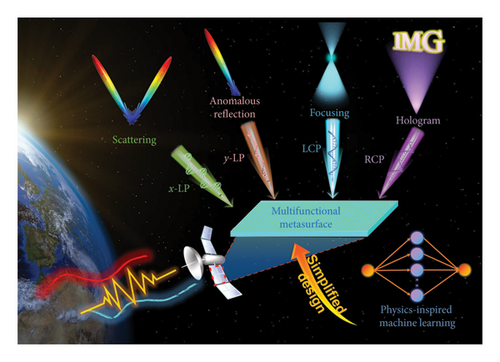
In this work, we propose a decoupling-inspired multiplexing neural network (MNN) to realize a multifunctional metasurface. According to the physics-inspired method based on decoupling of orthogonality and helicity, the bidirectional simplification between metasurface structure and neural network architecture can be achieved. First, a metasurface structure that can operate at both high and low frequencies is designed. The structure mainly consists of three layers, that is, high frequency control layer, low frequency control layer, and metal reflection plate. The low-frequency control layer consists of orthogonal metal wires, which can control the orthogonal linear polarized wave independently by changing the wire length at corresponding direction. The high frequency control layer consists of the umbrella-like structure, which can control the orthogonal circular polarized wave independently by changing the radian of branch at corresponding helicity. Owing to the low-frequency orthogonality and high-frequency helicity, phase modulation of the metasurface can be greatly simplified. Under this simplified design based on decoupling, the phase and structure parameters are only simple one-to-one mappings and the parameters can be independently controlled, which can be simplified to a single direction. Therefore, a simple three-layer neural network can be repeatedly applied to fit the structural parameters and EM responses, which is called network multiplexing. The MNN is trained on data with low and high frequencies, respectively. Also, all the data exhibit high fitting degree. As verification, we design four different phase profiles at x-linear polarization (x-LP), y-linear polarization (y-LP), left-hand circular polarization (LCP), and right-hand circular polarization (RCP). The four functions, that is, scattering, anomalous reflection, focusing and hologram are designed in a coaperture metasurface. The schematic diagram of decoupling-inspired MNN with applications is shown in Figure 1. The simulation and measurement are carried out to verify our design. All the results show a high degree of agreement with the design targets, which demonstrates the effectiveness of our design. Here, we provide a simple framework for machine learning with metasurface design based on physics inspiration, which can be extended to other multifunctional metasurfaces. Encouragingly, the simple framework can be easily integrated into current information systems, which paves the way for intelligent design.
2. Metasurface Design by Decoupling-Inspired MNN
2.1. Decoupling Meta-Atom Design
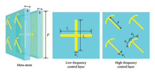
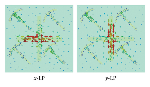
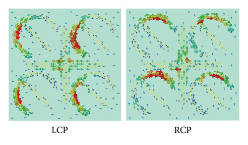
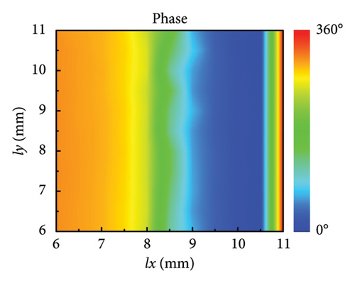
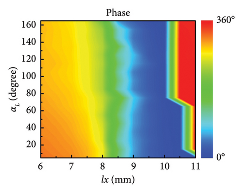
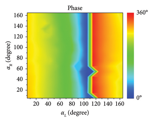
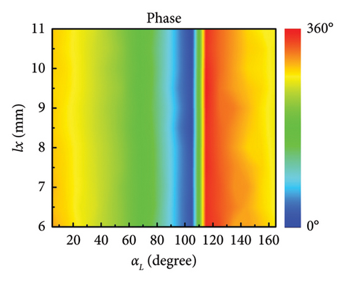
Here, the metasurface that can operate at both high and low frequencies is designed. The architecture of metasurface mainly consists of three layers, that is, high-frequency control layer, low-frequency control layer, and metal reflection plate. The diagram of meta-atom is illustrated in Figure 2(a), in which the geometrical parameters and layered patterns are annotated. The low-frequency control layer consists of orthogonal metal wires, which can control the orthogonal linear polarized wave independently by changing the wire length at corresponding direction [35, 63]. The high-frequency control layer consists of the umbrella-like structure, which can control the orthogonal circular polarized wave independently by changing the radian of branch at corresponding helicity [64–66]. The geometrical parameters are shown as follows. The length of periodical meta-atoms is p = 12 mm. The metal pattern is copper which is printed on the F4B dielectric substrate. The complex permittivity of F4B is 2.65(1 + 0.001j). The thickness of the dielectric substrate is h = 1.5 mm. In low-frequency control layer, the width of orthogonal metal wires is w1 = 0.7 mm. The surface currents under x-LP and y-LP incidence are monitored in Figure 2(b), where the surface currents are mainly concentrated on the metal wire corresponding to the polarization direction. The length of metal wire in x-direction is defined as lx, whose variation will affect the phase response of x-LP. Similarly, the variation of ly can control the phase response of y-LP. In high-frequency control layer, the width of metal wires is w2 = 0.3 mm. The length of straight metal wire is d = 4 mm. The radians of the left arm and right arm are represented as αL and αR, whose variations will affect the phase response of circular polarized wave. The surface currents under LCP and RCP incidence are monitored in Figure 2(c), where the surface currents are mainly concentrated on the metal arm corresponding to the helicity. The phase response of LCP will be affected by the radians of the left arm αL. Similarly, the variation of the right arm αR will affect the reflected phase under RCP incidence. The phase response of circular polarized wave can be analyzed by the Aharonov–Anandan (AA) phase, which is supported in Supporting Information Note 1 AA phase of umbrella-like structure. According to the surface current distributions at different polarizations, it can be concluded that the surface currents are separately concentrated on the corresponding metal patterns, thus implying the independent control capacity for manipulating the different polarized EM waves of this structure. Furthermore, the robustness of independent control is verified by observing the EM response while changing different parameters. Since the rotational is symmetry, it is sufficient to consider the effect of only a single polarization, for example, the effect of ly on lx is the same as that of lx on ly. The phase response of x-LP incidence at 9 GHz is shown in Figure 2(d) when ly and lx vary simultaneously. As shown in Figure 2(d), the phase of x-LP incidence can cover 0°–330° when lx vary from 6 mm to 11 mm and the variation of ly has almost no effect on the orthogonal phase. Similarly, Figure 2(e) illustrates the phase response of x-LP at 9 GHz when αL and lx vary simultaneously. Also, Figures 2(f) and 2(g) illustrate the phase response of LCP incidence at 16 GHz when lx, αR, and αL vary simultaneously, in which the phase can cover 0°–360° without needless parameters. Moreover, the amplitude responses of different polarizations and parameters are supported in Supporting Information Note 2 Analysis of meta-atom, which demonstrates the high efficiency of this unit. Meanwhile, the metasurface has certain angular stability and frequency stability, which is also supported in Supporting Information Note 2. All the results demonstrate that the phase modulation of different polarizations can be independently controlled with less crosstalk, which lays the foundation for subsequent simplified design.
2.2. Design and Training of MNN
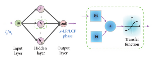
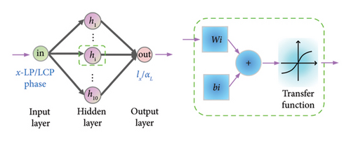
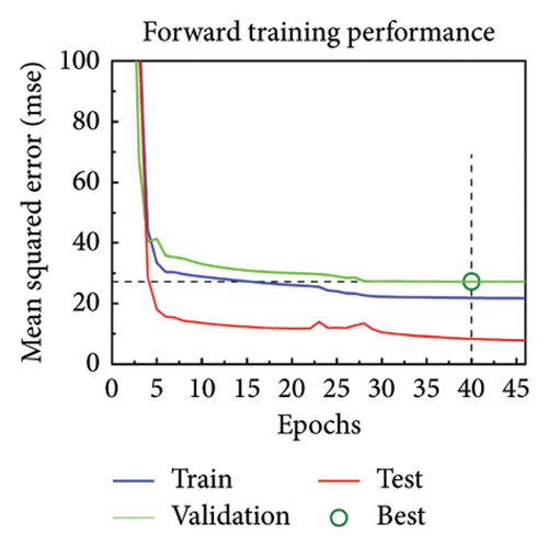
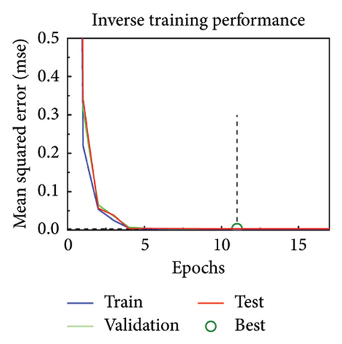
The orthogonal linearly polarized phase at 9 GHz can be modulated by adjusting the length of metal wires and the orthogonal circularly polarized phase at 16 GHz can be modulated by adjusting the radians of the arm. And importantly, the crosstalk among the various parameters is less, meaning that the relationship between the EM responses and structural parameters can be simplified as simple single mapping. Therefore, a simple artificial neural network consisting of only three layers can be used to fit these mapping relationships. The neural network is not only suitable for linear polarization but also suitable for circular polarization, so we call it MNN. From the point of view of fitting function, the model relationship after exchanging input and input is the inverse function relationship. The architecture of the neural network is identical for both forward design and inverse design. The architecture of MNN is exhibited in Figures 3(a) and 3(b), in which a simple network with three layers is designed. The network includes input layer, hidden layer, and output layer, which contain 1, 10, and 1 neuron, respectively. The difference between forward and inverse training is swapping the input and output variables with maintaining the structure and activation function. Input and output variables select structural parameters and EM response parameters according to the direction of forward and inverse design. The datasets are collected by parameter sweeping. Also, the data are divided into training set, validation set, and test set according to the ratio of 8:1:1. In low frequency, the lx length is between 6 mm and 11 mm, and the parameter sweeping is performed in steps of 0.01 mm. Therefore, a total of 501 sets of data were obtained. The quantity of training sets, validation sets, and test sets are 401, 50, and 50, respectively. In high frequency, the αL angle is between 5° and 165°, and the parameter sweeping is performed in steps of 0.25°. Therefore, a total of 641 sets of data were obtained. The quantity of training sets, validation sets, and test sets are 513, 64, and 64, respectively. Due to the small number of datasets, all the training data are directly used as a batch for network training. The Levenberg–Marquardt algorithm, which is usually used for training small amounts of data, is used to train the network. The initial learning rate is set to 0.001 and then the learning rate is adjusted adaptively with the gradient change. The more information of structure and training process of artificial neural network are supported in Supporting Information Note 3 Detailed network structure. The training is carried out in the computer with Windows 10 operating system, 16 GB RAM, and Intel Core i7-10710U CPU. The same MNN is used for training under linear polarization and circular polarization, respectively. Due to the bidirectional prediction of MNN, the forward design and inverse design can be concurrently realized by replacing input and output. Figures 3(c) and 3(d) illustrate the forward design and inverse design between the structural parameters lx and x-LP phase responses, where all the training performances fit well. All the training was completed within 100 epoch and in less than 10 s. Figures 3(e) and 3(f) illustrate the forward design and inverse design between the structural parameters αL and LCP phase responses, where all the training performance also fit well.
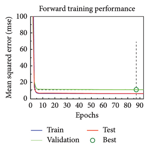
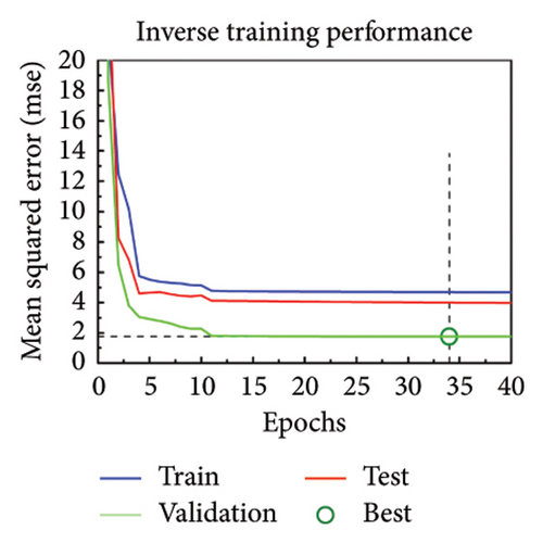
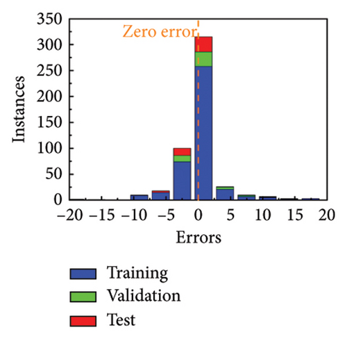
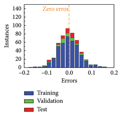
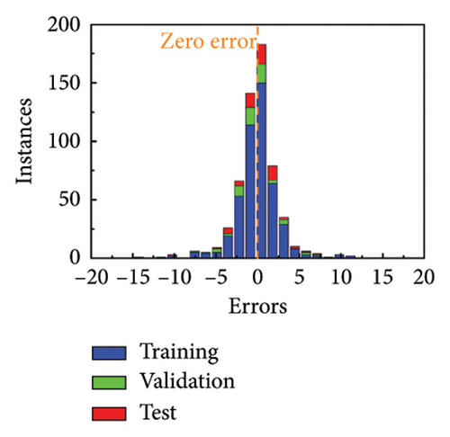
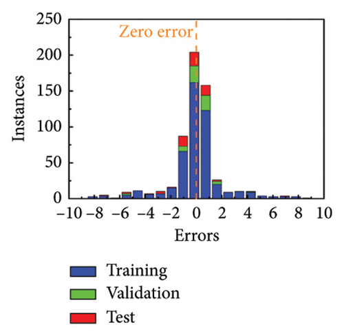
The error histograms of predicted value and true value are plotted to evaluate the training performance of MNN. Figures 3(g) and 3(h) show the error histograms of forward training and inverse training under linear polarization. Also, Figures 3(i) and 3(j) illustrate the situation of circular polarization. All the error histograms present a normal distribution, where most points are close to 0. The more evaluation metrics for training results are added in Supporting Information Note 4 Analysis of training results. Based on the high-precision model, the phase profiles can be quickly passed to generate the metasurface patterns.
The machine learning method provides a fitting model to adapt and extend the original dataset. From the point of view of algorithm, MNN and conventional methodologies can be demonstrated from the point of time complexity. The conventional methodologies, like the look-up-table approach, require traversing all the data to match the desired data points. Therefore, time complexity can be represented as O(n). However, the trained MNN obtains the corresponding output parameters through numerical calculation of the coefficient matrix, so the calculation time is only constant, so the time complexity can be expressed as O(1). In terms of time complexity, the MNN method requires less time. On the other hand, the MNN method builds a data fitting model, which effectively expands the data volume in another dimension. The machine learning method will take a certain amount of time to train; however, once the training is complete, this time cost will be evenly shared in the subsequent multiple uses. Therefore, the MNN method has more efficient computing power than the traditional traversal method.
2.3. Multifunctional Metasurface Design and Verification
Based on the MNN fitting performance, the multifunctional metasurfaces can be fast generated according to different phase profiles. Here, the scattering, anomalous reflection, focusing, and hologram are designed as target functions of the multifunctional metasurface. In x-LP incidence at 9 GHz, the scattering function is set according to the coding phase profile, which is plotted in Figure 4(a). In y-LP incidence at 9 GHz, the anomalous reflection is designed according to generalized Snell’s law and the phase profile is shown in Figure 4(b). In LCP incidence at 16 GHz, the focusing function is set according to parabolic profile, which is plotted in Figure 4(c). In RCP incidence at 16 GHz, the hologram function is set according to the Gerchberg–Saxton (GS) algorithm and the theoretical phase profile is calculated in Figure 4(d). The more calculation methods and equations about scattering, anomalous reflection, focusing, and hologram are supported in Supporting Information Note 5 Functions design. The calculated phase profiles are input into the trained MNN and the corresponding geometrical parameter distributions are obtained. The length of wire distributions of x-LP and y-LP at 9 GHz are shown in Figures 4(e) and 4(f). The angle of arm distributions of LCP and RCP at 16 GHz are shown in Figures 4(g) and 4(h).
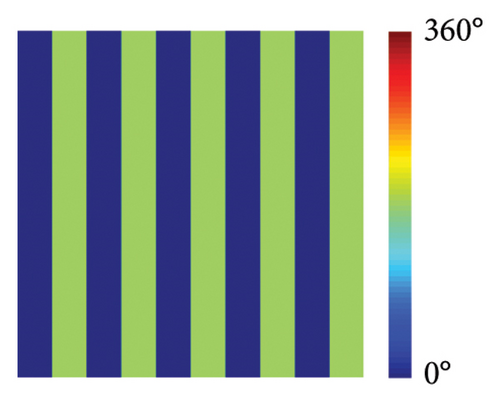
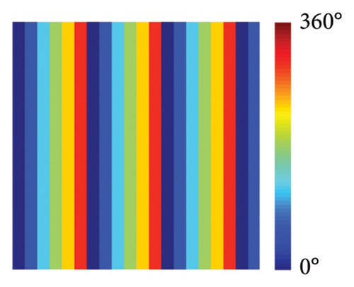
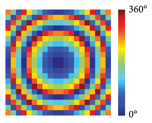
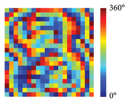
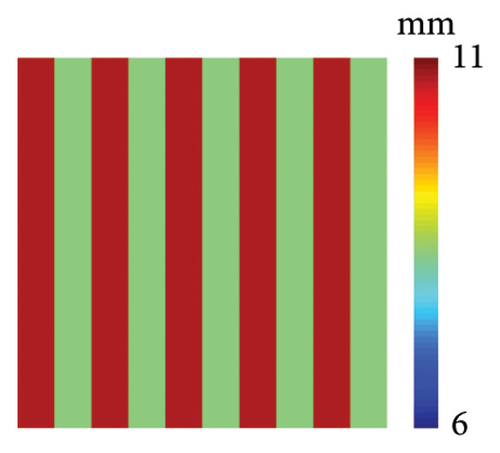
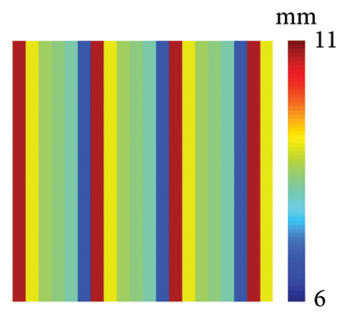
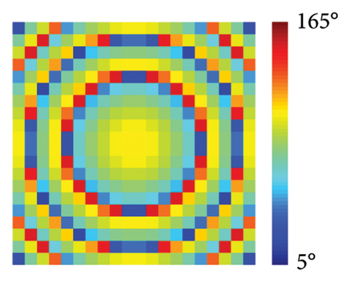
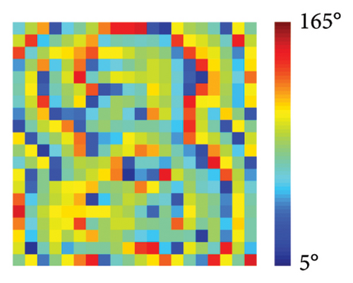
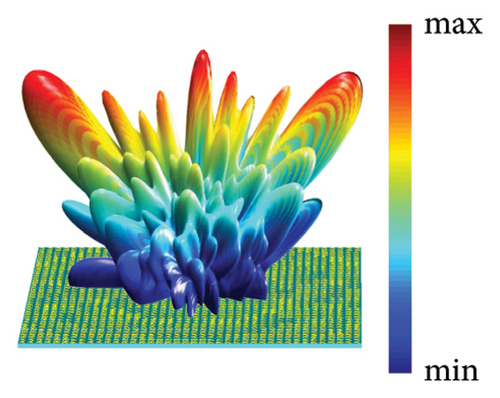
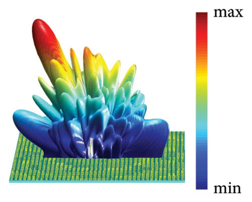
As shown in Figures 4(e), 4(f), 4(g), and 4(h), the geometrical parameters [lx, ly, αL, αR] of meta-atoms can be predicted from phase profiles by the MNN. The meta-atoms can be fast established according to the predicted parameters and the metasurface can be fabricated by assembling these meta-atoms. To verify our design, full-wave simulation is carried out in CST Microwave Studio. The metasurface is placed on the xoy plane and the different polarized plane wave is perpendicularly incident from the z-direction. All the boundary conditions are set to open (add space). The time-domain solver is applied to calculate the performance of metasurface. Far-field monitor at 9 GHz is set to observe the far-field scattering mode. E-field monitor at 16 GHz is set to observe the electric field distributions. In x-LP wave incidence at 9 GHz, the 3D far-field result is shown in Figure 4(i), in which the incident wave is split into two beams. At this point, the backscattering is effectively reduced and the main lobe is split at an orientation of about ±43°, which is consistent well with the theoretical calculation of the coding scattering equation. In y-LP incidence at 9 GHz, the 3D far-field result is shown in Figure 4(j), in which the incident wave is deflected to other directions. At this point, the deflection angle of the main lobe is about 28°, which is consistent well with the calculation of the generalized Snell’s law. In LCP incidence at 16 GHz, the copolarized electric intensity distributions on xoz plane are recorded in Figure 4(k), where the most powerful intensity areas are concentrated in 150 mm, that is, the focal length is 150 mm. In RCP incidence at 16 GHz, the copolarized electric intensity distributions on xoy plane at z = 100 mm is recorded in Figure 4(l), where the copolarized electric intensity distribution on the imaging plane presents the letter ‘z’. Since the size of the metasurface is only 12.8λ, the aperture surface is small, and only the phase is used for imaging, the convergence of the imaging surface capacity is not uniform. However, the present letters still demonstrate the design of the hologram. All the simulated results satisfy the theoretical design well, which demonstrates the metasurface design ability of MNN.
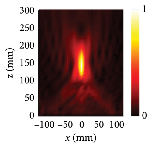
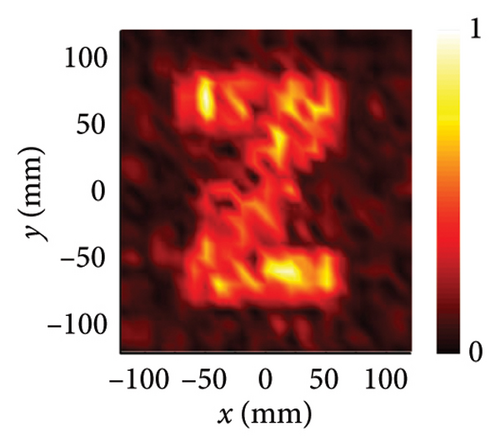
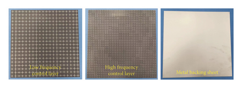
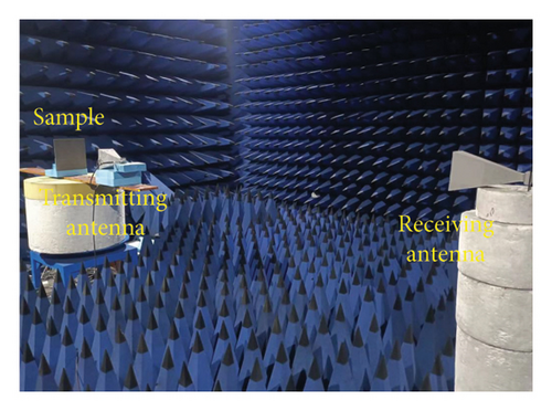
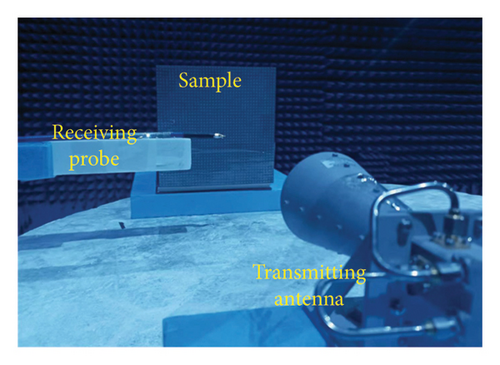
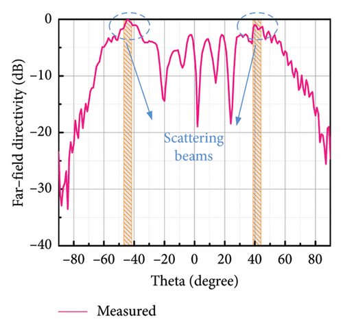
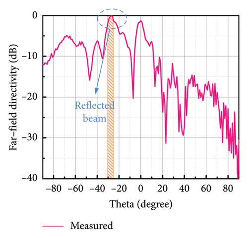
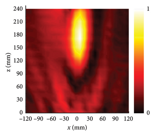
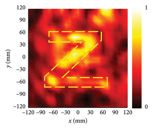
To further verify our design, the prototype of multifunctional metasurface is fabricated and measured. The photograph of the metasurface sample is shown in Figure 5(a), which is processed by printed circuit board (PCB) technology. In order to ensure the accuracy of the fabrication, the low-frequency control layer and high-frequency control layer are etched on the front and back sides of the F4B dielectric substrate. The metasurface is composed of 20 × 20 meta-atoms with the scale of 240 mm × 240 mm. Both the far-field measurement and near-field measurements were carried out with vector network analyzer (VNA) in microwave anechoic chamber to reduce the unnecessary EM interference. The functions of scattering and anomalous reflection are measured by far-field measurement environment, which are shown in Figure 5(b). The operation frequency of far-field measurement is 9 GHz. The sample of metasurface is placed at rotating platform. The horn antenna is placed perpendicular to the sample as transmitting antenna, and another horn antenna is set as receiving antenna. The far-field radiation patterns at x-LP incidence and y-LP incidence are recorded by the measurement system. Figure 5(d) illustrates the far-field radiation pattern under x-LP incidence, in which the main lobe is split into two beams. Also, the half-beam angle of the scattering beam in Figure 5(d) covers ±43°, which is consistent well with simulation and theoretical calculation. Figure 5(e) illustrates the far-field radiation pattern under y-LP incidence, in which the main lobe is deflected to the normal direction of 28°. The measured deflected angle is consistent well with the simulation result and theoretical calculation. The functions of focusing and hologram are measured by near-field measurement environment, which are shown in Figure 5(c). The operation frequency of near-field measurement is 16 GHz. The metasurface is placed at the measured platform, and the coaxial probe is placed away from the sample to detect the electric field distribution in space. The circularly polarized horn antenna is set as transmitter to radiate circularly polarized waves to metasurfaces. When LCP wave is at incident, the probe scans the xoz plane, in which the normalized electric intensity distribution is plotted in Figure 5(f). The region of 240 mm × 240 mm (x ∈ [−120, 120] and z ∈ [0, 240]) in the xoz plane perpendicular to sample is selected as the scanning area. Figure 5(f) clearly indicates that the strongest intensity areas are concentrated around 150 mm, that is, the focal length is 150 mm. Herein, the horn antenna is used in the measurement; the wider beamwidth and the lower main lobe gain are slightly different from the ideal situation of the simulation. These differences result in a larger focal spot formed during the focusing process, but the focus is still near 150 mm, which can still verify the focusing function design. Homoplastically, the region of 240 mm × 240 mm (x ∈ [−120, 120] and y ∈ [−120, 120]) in the xoy plane parallel to sample is selected as the scanning area under RCP incidence. When RCP wave is at incident, the probe scans the xoy plane at z = 100 mm and normalized electric intensity distribution is portrayed in Figure 5(g), in which the letter ‘z’ is reconstructed on the imaging plane. Since the size of the metasurface is only 12.8λ, the aperture surface is small, only the phase is used for imaging, and the convergence of the imaging surface capacity is not uniform. However, the present letters still demonstrate the design of the hologram. All the measured results are consistent well with the simulation and theoretical design, which fully demonstrates the powerful design ability of the MNN.
3. Conclusion
In this work, we propose a machine learning framework with decoupling-inspired MNN to design multifunctional metasurface. According to the physics-inspired method based on decoupling of orthogonality and helicity, the bidirectional simplification between metasurface structure and neural network architecture can be achieved. With the decoupling design, the phase responses of x-LP, y-LP, LCP, and RCP can be independently controlled by four separate parameters. Due to the independence of phase modulation and parameter tuning, the mapping between structural parameters and phase responses can be established using only a simple artificial neural network. As verification, the four functions, that is, scattering, anomalous reflection, focusing, and hologram are integrated in a same aperture. The simple neural network can be multiplexed to realize multifunctional metasurface design, which effectively solves the problem of complex network architecture caused by multiparameters in function integration design. Importantly, this work paves a new way to design metasurface by physics-inspired machine learning, which has potential applications in areas such as satellite communications.
4. Experimental Section
4.1. Measurement Environment
Both near-field measurements and far-field measurements are carried out in a microwave anechoic chamber. The near-field measurement system includes a vector network analyzer (Agilent E8363B), circularly polarized antenna, and x/y-polarized probe. Circularly polarized antenna is set as transmitter and the probe is set above the samples as receiver to monitor the electric field distribution in space. The far-field measurement system includes a turntable mount, vector network analyzer, and a pair of X-band horn antennas. The samples are placed on the turntable mount to measure the scattering directivity diagram. A pair of X-band horn antennas is employed for measurement, one of which is used as transmitter and the other as receiver.
4.2. Sample Fabrication
The prototypes of metasurfaces are fabricated and assembled by commercial PCB technology. The pattern is printed in the substrate. The substrate is F4B with a dielectric constant εr = 2.65 and a loss tangent tanδ = 0.001. The sample size is 240 × 240 mm. The structures of the low and high frequency layers are printed on both sides of the substrate layer to ensure accurate relative positions.
Conflicts of Interest
The authors declare no conflicts of interest.
Funding
This research was supported by the National Natural Science Foundation of China ∗ 62401614 ∗ 62101588 ∗ 62201609 Natural Science Foundation of Shaanxi Province ∗ 2024JC-YBQN-0617 National Key Research and Development Program of China ∗ 2022YFB3806200.
Supporting Information
Supporting Information is available from the Wiley Online Library or from the author. The supporting file includes Note 1. Aharonov–Anandan phase of umbrella-like structure. Note 2. Analysis of meta-atom. Note 3. Detailed network structure. Note 4. Analysis of training results. Note 5. Functions design.
Open Research
Data Availability Statement
The data that support the findings of this study are available from the corresponding author upon reasonable request.


