Electromagnetic–Thermal–Mechanical Collaborative Optimized Design of Permanent Magnet Synchronous Motors Used in Concrete Stirring Tankers
Abstract
The motor involves many factors such as electricity, magnetism, heat, and stress, and thus, electromagnetism, heat, and rotor mechanical structure must be comprehensively considered in motor designing. Here, an electromagnetic–thermal–mechanical structured collaborative optimized design method was proposed for permanent magnet synchronous motors (PMSMs) used in concrete stirring tankers in accordance with the requirements of large torque and low speed. With a water-cooled PMSM with rated power of 47 kW as example, the stator and rotor structures of the PMSM for stirring tankers were optimized on finite element software. Then, the temperature field of the motor and the mechanical structural stress of the rotor were analyzed and designed. The finite element simulation showed the design solution can meet the electromagnetic performance, temperature field performance, and rotor mechanical structural strength required by the motor. Finally, a prototype was made and tested. The experimental results were consistent with the simulation results, which proves the effectiveness and correctness of the motor optimized design method proposed here.
1. Introduction
When a concrete stirring tanker is working, the motor driving the tank is required to have low speed and high torque, and thus, motor characteristics shall be given priority in designing.
The motor involves multiple physical field factors, such as electricity, magnetism, and heat, which all interact and influence each other. As for the design method of vehicular permanent magnet motors and to improve the design performance of motors, the motors must be simulated and designed in multiple physical domains, such as electromagnetism, temperature, and mechanical stress [1–3]. To improve the power density and torque density of vehicular motors, scholars have conducted numerous optimization designs on the motor structure. The design of the rotor structure has changed from the original “—” structure to the “—” structure, the “U” structure and a combination of multiple structures, such as “V + —”, double “U”, “U + —”, and “V + U” [4–8]. The salient pole rate of rotor magnetic circuit, and the rotor reluctance torque of the motor can be improved by optimizing the rotor structure [5, 9]. The motor torque and thereby the motor torque density can be improved from the aspect of reluctance torque.
In terms of motor stator structure optimized design, Deng et al. proposed an improved stator design method for a surface-mounted outer rotor transversal flux permanent magnet motor, which can convert a part of leaked magnetic flux into main magnetic flux and improve the motor output torque [10]. Zheng et al. proposed an armature tooth and tooth boot offsetting method for permanent magnet motors by making full use of the armature slot area [11]. This method increased the output torque of motors, reduced torque ripple, and solved the problem faced by traditional permanent magnet motors that they cannot consider fault tolerance, power density, and torque ripple at the same time.
In all, the above methods all optimize motor stator and rotor design and improve the power density and torque density of motors, but do not consider the mutual influence of multiple physical domains. Reference [12] conducted a multiphysics optimization design for a high-efficiency, high-power-density hairpin-winding permanent magnet synchronous motor with a rated power of 50 kW and a rated speed of 2050 r/min. This included the design and simulation analysis of electromagnetic, thermal, and stress fields. However, it lacked optimization design for the rotor structure and did not involve experimental testing for validation. Reference [13] performed an electromagnetic–thermal optimization design for a 48-slot/8-pole automotive permanent magnet motor but did not consider the influence of rotor mechanical structural strength. Currently, there is extensive research on multiphysics analysis of permanent magnet motors, but studies on the design of permanent magnet synchronous motors for concrete stirring tankers remain relatively scarce.
This paper proposes a multiphysics co-optimization design method for permanent magnet synchronous motors used in concrete stirring tankers, encompassing electromagnetic, thermal, and rotor mechanical structural strength aspects. Under the premise of fully considering the mutual influences among these three physical fields, the stator and rotor structures of the motor were optimized, leading to improved motor efficiency and torque. By avoiding the time-consuming issue of fluid field–based temperature calculations, the design efficiency of the motor was enhanced. This approach provides a highly effective methodology for the engineering design of permanent magnet motors.
2. Optimal Design of PMSM for Mixing Tankers
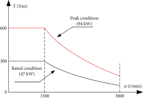
The main requirements for performance indices and dimensions of permanent magnet motors used in mixing tankers are shown in Figure 1 and Table 1.
| Parameter | Value | Parameter | Value |
|---|---|---|---|
| Rated power (kW) | 47 | Maximum torque (N·m) | 600 |
| Rated speed (r/min) | 1500 | Core length (mm) | ≤ 115 |
| Rated torque (N·m) | 300 | Outer diameter of the stator (mm) | ≤ 290 |
| Maximum power (kW) | 94 | Winding temperature (°C) | ≤ 155 |
| Maximum speed (r/min) | 3800 | Cooling method | Water cooling |
| Maximum efficiency | ≥ 96% |
2.1. Estimation of Main Dimensional Parameters of the Motor
Clearly, when the electromagnetic load, effective length of iron core, relevant waveform coefficient, and winding coefficient of the permanent magnet motor for stirring tankers are constant, the electromagnetic torque of the motor is decided by its armature diameter and iron core length.
2.2. Optimized Design of Stator Structure
The design of the PMSM stator for stirring tankers must take into account both thermal and electromagnetic properties. During heat design of the motor, a suitable cooling and heat dissipation structure that ensures complete heat dissipation in the motor shall be chosen. The electromagnetic design shall be maximally optimized to reduce the loss and total heat flux density of the motor. The heat conduction structure must be reasonably designed and arranged to reduce thermal resistance and heat flow density, reducing heat conduction temperature difference in the motor. The main reasons for the excessively high winding temperature in the motor stator include the high heat flux density of copper consumption and the excessive thickness of the winding paint layer. Increasing the number of stator slots and reducing the slot width can effectively reduce the winding temperature [16, 17].
While the motor volume, rotor structure, and the inner and outer diameters were unchanged, the most effective way to reduce copper consumption and heat flux density is to increase the number of stator slots, which means to change the 36-slot/12-pole to 72-slot/12-pole (Figure 2).
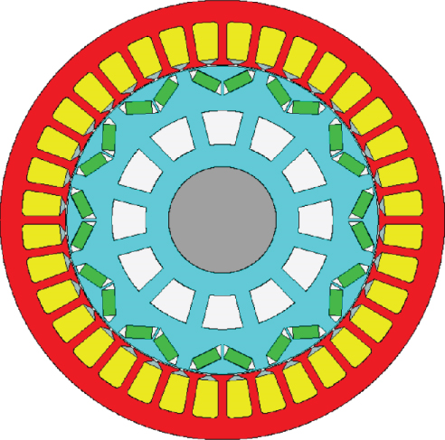
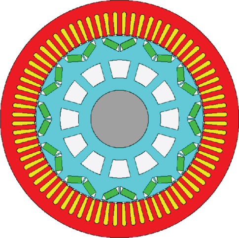
The motor design parameters before and after optimization of stator winding thermal performance are shown in Table 2. The optimized 72-slot/8-pole winding end was longer, leading to an increase in winding copper loss and heat load. However, the winding heat transfer area was enlarged by 1.5 times. Therefore, the copper heat flux density and the equivalent paint layer thickness of winding were significantly reduced, which lowered the stator winding temperature by 23.1°C.
| Parameter | Before optimization | After optimization |
|---|---|---|
| Number of stator slots | 36 | 72 |
| Stator slot width (mm) | 14.9 | 4.6 |
| Copper loss (W) | 1095 | 1205 |
| Core loss (W) | 262 | 340.5 |
| Heat transfer area for copper loss (cm2) | 3593.9 | 5478.1 |
| Thermal load (A2/(cm∗mm2)) | 1417.6 | 1559.4 |
| Winding heat flux density (W/cm2) | 0.3 | 0.2 |
| Winding temperature (°C) | 128.7 | 105.6 |
Generally, the heat load is proportional to the copper loss and is linearly related with the stable temperature rise. Clearly, the use of thermal load alone is impossible to design and predict the temperature rise of a water-cooled motor (Table 2). Instead, the winding insulation heat conduction structure must be reasonably designed and arranged, and the copper loss and the equivalent paint layer thickness of winding must be controlled so as to effectively reduce winding insulation temperature difference and control stator winding temperature.
2.3. Optimized Design of Motor Rotor Structure
To reduce the capacity of inverter IGBT and thus reduce costs, the peak counter potential at the motor’s fastest no-load line is lower than the highest safe voltage of the drive system device but is much higher than the rated voltage of DC bus. As a result, field weakening control is needed when the motor load is running at high speed, so that the peak counter potential of the load line is lower than the rated voltage of DC bus. Otherwise, the current cannot flow into the motor at high speed and is prone to out-of-control. The salient pole rate of the rotor directly reflects the torque/current ratio capability of the motor. In addition, the reluctance torque generated is also larger, which can reduce the capacity of the IGBT and reduce costs. Clearly, selecting a rotor structure with high salient pole ratio is a key in motor design.
Based on the technical requirements and comparison of salient pole rate and process difficulty for permanent magnet motors with different rotor structures, we chose an embedded V-shaped rotor structure with flexible design, simple structure, and high salient pole rate for the PMSM used in stirring tankers.
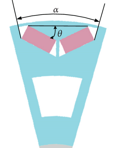
For the V-shaped rotor structure, the polar arc angle and the magnet tilt angle largely influence the electromagnetic performance of the motor. The optimization of pole arc angle and magnet tilt angle endows the motor with a better sinusoidal magnetic density waveform, which enhances system controllability and high-speed field weakening operating performance, and reduces control difficulty and torque ripple. Many factors affect radial magnetic density. The magnet length, stator slot width, and the width of magnetic isolation bridge all affect the waveform. Then, the influence of pole arc angle and magnet tilt angle on the electromagnetic performance of the motor was analyzed (Figure 3).
2.3.1. Effect of Polar Arc Angle on Electromagnetic Performance
To clearly and directly reflect the influence of polar arc angle α on the air gap magnetic density, we kept the width of magnetic isolation bridge, magnet length, slot width, and magnet inclination angle constant during the optimization. The design was optimized in the finite element software to determine the no-load air gap magnetic density under different polar arc angles. Each waveform was Fourier-decomposed to determine the proportion of each harmonic component in the fundamental wave. Since the proportions of harmonic components above the 17th order were small, only the proportions of low-order harmonic waves were studied here.
Table 3 shows the numerical results from fast Fourier transform (FFT) of each harmonic wave of the air gap magnetic density under different polar arc degrees. When the inclination angle of the magnetic steel was the same, the proportions of the 5th- and 7th-order harmonic waves changed largely with the pole arc angle. The proportions decreased as the degree of pole arc varied within 18° and 22° but increased as the degree of polar arc rose in the range of 22° and 24°. From the perspective of total distortion rate, the sine of radial magnetic density was the best when the polar arc degree was 22°. Thus, the polar arc angle was determined to be 22°.
| Pole arc degree (°) | 18 | 20 | 22 | 24 |
|---|---|---|---|---|
| Fundamental wave amplitude (T) | 0.907 | 0.907 | 0.908 | 0.908 |
| Third-order harmonic proportion (%) | 1.03 | 0.90 | 0.89 | 0.83 |
| Fifth-order harmonic proportion (%) | 19.58 | 19.44 | 19.40 | 19.53 |
| Seventh-order harmonic proportion (%) | 13.28 | 13.24 | 13.18 | 13.22 |
| Ninth-order harmonic proportion (%) | 1.72 | 1.67 | 1.70 | 1.70 |
| 11th-order harmonic proportion (%) | 19.00 | 18.92 | 18.90 | 18.86 |
| 13th-order harmonic proportion (%) | 11.40 | 11.45 | 11.50 | 11.54 |
| 15th-order harmonic proportion (%) | 1.09 | 1.12 | 1.16 | 1.20 |
| 17th-order harmonic proportion (%) | 0.79 | 0.78 | 0.78 | 0.77 |
| Distortion rate (%) | 32.50 | 32.37 | 32.33 | 32.42 |
2.3.2. Effect of Magnet Steel Inclination Angle on Electromagnetism
To clearly and intuitively reflect the influence of the inclination angle θ of magnetic steel on air gap magnetic density, the thickness of magnetic isolation bridge, magnetic steel length, slot width, and polar arc angle were always kept constant during the optimization. Optimal design calculations were performed in the finite element software to determine the no-load air gap magnetic density at different magnet tilt angles. Each waveform was Fourier-decomposed to obtain the proportion of each harmonic component in the fundamental waves. Since the proportions of harmonic components above the 17th order were small, only low-order harmonic waves were studied here.
Table 4 shows the numerical results of FFT of air gap magnetic density under different magnet tilt angles. When the polar arc angle was the same, the proportions of the 3rd and 7th harmonic waves changed greatly with the inclination angle of the magnetic steel. The proportions decreased as the magnetic steel inclination angle rose within 6.5° and 26.5° but increased as the inclination angle rose in the range of 26.5° and 36.5°. From the perspective of total distortion rate, the sine of air gap magnetic density was the best when the magnet inclination angle was 26.5°. Therefore, it is determined through optimization simulation comparison that the inclination angle of magnetic steel is 26.5°.
| Magnetic steel inclination angle(°) | 6.5 | 16.5 | 26.5 | 36.5 |
|---|---|---|---|---|
| Fundamental wave amplitude (T) | 0.866 | 0.889 | 0.897 | 0.925 |
| Third-order harmonic proportion (%) | 5.52 | 4.32 | 3.52 | 10.59 |
| Fifth-order harmonic proportion (%) | 16.31 | 16.67 | 16.29 | 21.75 |
| Seventh-order harmonic proportion (%) | 16.61 | 15.62 | 13.35 | 16.05 |
| Ninth-order harmonic proportion (%) | 3.90 | 2.48 | 1.71 | 6.49 |
| 11th-order harmonic proportion (%) | 17.30 | 17.76 | 18.00 | 15.82 |
| 13th-order harmonic proportion (%) | 8.29 | 8.92 | 11.61 | 16.81 |
| 15th-order harmonic proportion (%) | 1.62 | 0.53 | 1.15 | 0.82 |
| 17th-order harmonic proportion (%) | 0.56 | 0.64 | 0.79 | 1.28 |
| Distortion rate (%) | 30.96 | 30.69 | 30.33 | 34.88 |
3. Finite Element Simulation Design and Analysis of PMSM for Stirring Tankers
3.1. Electromagnetic Performance Simulation
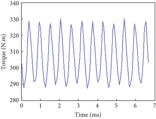
The electromagnetic torque waveform of the prototype under rated rotation speed and rated current was simulated (Figure 4). The average electromagnetic torque was 306.45 Nm. The torque ripple was calculated ((maximum torque − minimum torque)/average torque) to be 13.93%, meeting the requirement of torque ripple. Under rated working conditions, the efficiency obtained from simulations at 1500 r/min@300 Nm and 3800 r/min@118 Nm was 96.8% and 95.8%, respectively. Simulations showed the efficiency at 1500 r/min@600 Nm and 3800 r/min@236 Nm under peak operating conditions was 94.7% and 95.1%, respectively. Both electromagnetic torque and efficiency meet the motor design requirements.
3.2. Temperature Performance Simulation
The temperature field of the prototype was simulated and calculated on finite element software. The experimental inlet water temperature of the water cooling system was set at 65°C, the water flow rate was 15 L/min, and the coolant composition was EGW50/50.
The temperature simulation results of each key part of the motor are shown in Table 5. The working Conditions (1) to (4) are as follows: 1500 r/min@300 Nm, 3800 r/min@118 Nm, 1500 r/min@600 Nm, and 3800 r/min@236 Nm. The maximum temperature of the motor (126°C) appeared on the stator winding (Table 5), which meets the motor temperature requirements.
3.3. Analysis of Strength and Performance of Rotor Mechanical Structure
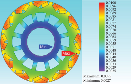
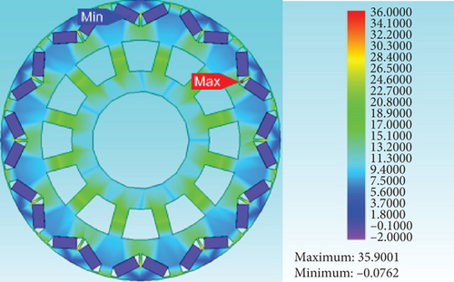
The maximum rotation speed of the PMSM for tankers designed here is 3800 r/min. With a margin of 1.5 times, the motor operates safely at 5700 r/min. To ensure the electromagnetic performance of the motor was unaffected during high-speed operation, the maximum deformation at the outer surface of the rotor at 3800 r/min must not exceed 5% of the air gap length of the motor. To meet such stringent index requirement, the motor rotor structure must have high mechanical strength. Based on the finite element software, rotor structure stress simulation was carried out when the prototype was running at 5700 r/min. The simulation results are shown in Figure 5. The material properties are shown in Table 6.
| Silicon steel material name | Young’s modulus | Poisson’s ratio | Density (g/cm3) | Tensile strength (MPa) | Yield strength (MPa) |
|---|---|---|---|---|---|
| B35AV1900 | 207,000 | 0.30 | 7.85 | 530 | 395 |
| N48UH | 15,000 | 0.28 | 7.6 | 80 | — |
| New epoxy material | 11,000 | 0.38 | 1.84 | 60 | — |
The maximum deformation on the rotor surface was 0.0095 mm and the maximum centrifugal stress was 35.9 MPa, which are both smaller than the maximum deformation (0.035 mm) and maximum yield strength (395 MPa) (Figure 5). When the rotor structure was operated at 1.5 times the maximum rotation speed, the maximum deformation on the rotor surface and the maximum centrifugal force can both meet the design requirements for the mechanical strength of the rotor, ensuring long-life operation of the motor.
4. Prototype Experiment
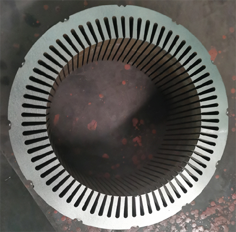
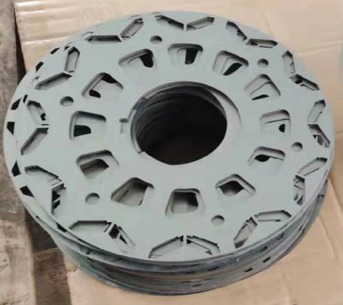
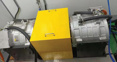
The stator and rotor structure of the prototype were shown in Figure 6. The test experimental platform containing two motors at a rated power of 47 kW and operated in parallel was shown in Figure 7. The system was equipped with a water cooling system, and thermistors were placed inside the motor end winding, the outer wall of the machine base, and the water inlet and outlet of the machine base to detect the temperature of each component.
4.1. Basic Performance Test of Prototype
4.1.1. Output Torque and Output Power Test
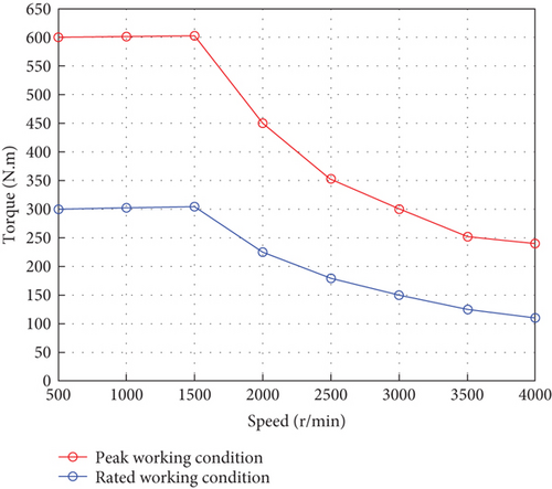
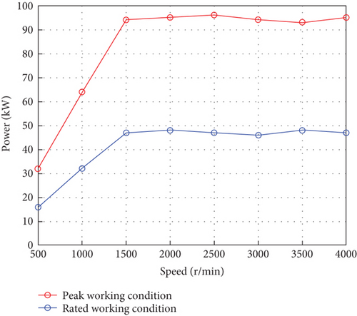
The torque curve of the prototype was shown in Figure 8a. When the motor was running in the constant torque zone, it outputted 300 and 600 Nm torque under rated and peak working conditions, respectively. The motor power curve was shown in Figure 8b. When the motor was operating in the constant power zone, the constant power under the rated and peak operating conditions was 47 and 94 kW, respectively. The output torque and output power of the prototype meet the motor design requirements.
4.1.2. Output Efficiency Test
Comparison of prototype efficiency between simulation and experiment was shown in Table 7. The two values are basically consistent, with the maximum error of 1.91%, and the motor efficiency meets the technical index requirements.
| Working condition | Simulated value (%) | Experimental value (%) | Error (%) |
|---|---|---|---|
| 1500 r/min@300 N·m | 96.8 | 96.1 | 0.73 |
| 3800 r/min@118 N·m | 95.8 | 94.0 | 1.91 |
| 1500 r/min@600 N·m | 94.7 | 93.5 | 1.28 |
| 3800 r/min@236 N·m | 95.1 | 94.3 | 0.85 |
4.2. Prototype Temperature Rise Test
The experimental water temperature of the water cooling system was set at 65°C and the water flow rate was 15 L/min. The comparison of stator winding temperature of the prototype between experiment and simulation was shown in Table 8. The simulated stator winding temperature is consistent with the experimental value.
| Working condition | Simulated value (°C) | Experimental value (°C) |
|---|---|---|
| 1500 r/min@300 N·m | 105.6 | 108.0 |
| 3800 r/min@118 N·m | 115.0 | 118.0 |
5. Conclusions
- 1.
The design of polar arc angle and magnet inclination angle in the motor rotor structure was optimized. The best polar arc angle was 22°, and the best magnet inclination angle was 26.5°. The electromagnetic torque and operating efficiency of the motor under four working conditions were simulated, and all meet the motor design requirements.
- 2.
The temperature field of the motor was simulated and analyzed. The maximum temperature of the motor stator winding was 126°C, which meets the motor temperature requirements.
- 3.
The rotor mechanical structure stress was simulated at 1.5 times the maximum rotation speed of the motor. The rotor deformation and maximum centrifugal force both meet the requirements of mechanical structure strength.
- 4.
A prototype was made and tested. The test results are consistent with the simulation results, indicating the proposed optimization design method for PMSMs in tankers is effective and correct and has much value for engineering applications.
Conflicts of Interest
The authors declare no conflicts of interest.
Funding
This work was supported by the Anhui Province Key R&D Program High tech Field Project (Grant No. 202304a05020084), the 2024 Anhui Province University Science and Engineering Teachers’ Internship Program in Enterprises (Grant No. 2024jsqygz47), and the Anhui Province Higher Education Scientific Research Project (Grant No. 2024AH051084).
Acknowledgments
This work was supported by the Anhui Province Key R&D Program High tech Field Project (Grant No. 202304a05020084), the 2024 Anhui Province University Science and Engineering Teachers’ Internship Program in Enterprises (Grant No. 2024jsqygz47), and the Anhui Province Higher Education Scientific Research Project (Grant No. 2024AH051084).
Open Research
Data Availability Statement
The nature of the data is the motor size parameters, and the data can be accessed from Electrical Machinery Laboratory of Anqing Normal University. The complete data belong to the joint ownership of the Electrical Machinery Laboratory of Anqing Normal University and the enterprise.


