Comparative Evaluation of Printed Rectenna Topologies on Unconventional Substrates for Enhanced RF Energy Harvesting
Abstract
This study investigates four rectenna system configurations using microstrip patch antennas with different geometries fabricated on various substrates, including glass, paper, fiberglass (FR4), and polyester fabric. A voltage doubler rectifier circuit was designed for each antenna type to enhance performance. Metamaterial cells were incorporated into the glass, FR4, and paper-based systems to improve electromagnetic wave capture. Simulations and optimizations were conducted using computer simulation technology (CST) and advanced design system (ADS) for operation at 2.45 GHz. Both the simulated and measured results that were obtained validate the potential of the proposed systems as efficient energy-harvesting solutions.
1. Introduction
The rapid advancement of mobile technologies—including industrial sensors, smartphones, laptops, tablets, smartwatches, and audio devices—has significantly accelerated the adoption of wireless communication standards such as Bluetooth, Wi-Fi, radio frequency, 4 G, and 5 G. This expansion has enabled the integration of people, machines, processes, and data through wireless connectivity [1]. However, the increasing number of interconnected devices has led to a substantial rise in energy demand while maintaining the need for mobility. To address this challenge, researchers are developing innovative solutions for wireless energy transmission and harvesting [2]. Among these, the rectenna stands out as a promising technology. This system consists of an antenna that captures RF signals available in the environment and a rectifier circuit that converts them into direct current to power electronic devices [3–7]. The development of rectennas faces key challenges, including impedance matching, fabrication complexity, and environmental signal stability. Overcoming these challenges requires advancements in fabrication techniques, using low-loss materials with improved electromagnetic properties, and careful optimization of impedance matching, diode nonlinearity, and the impact of varying input power levels.
Accordingly, this study contributes to advancing energy harvesting technologies by investigating the use of different dielectric substrates—glass, fiberglass (FR4), fabric, and paper—in rectenna systems. Exploring these materials aims to optimize rectenna performance while enabling integration into diverse environments, such as windows, wallpaper, electronic circuits, and wearable applications [8–12]. In addition, the study examines the incorporation of metamaterial (MTM) structures to enhance electromagnetic wave capture and improve system efficiency [13, 14]. The proposed rectennas operate at 2.45 GHz (Wi-Fi) and consist of a voltage doubler rectifier circuit (VDRC) integrated with a microstrip patch antenna (MPA). They were designed and simulated using computer simulation technology (CST) and advanced design system (ADS) software to optimize directivity, gain, and minimize S11 values, ensuring efficient RF-to-DC conversion.
The MPA geometry and construction processes were carefully selected to suit the unique characteristics of each substrate. For glass, the priority was transparency to minimize visual impact. Paper and FR4 allowed greater flexibility in geometric design, while the fabric-based antenna, intended for wearable applications, incorporated natural patterns inspired by tree structures to maintain aesthetic appeal. To validate the feasibility and performance of the proposed systems, experimental testing was conducted, including voltage measurements and efficiency calculations. This evaluation provides a comparative analysis of different rectenna configurations, demonstrating their potential for practical energy harvesting applications.
2. Used Materials
This study investigates the design of rectennas utilizing four different dielectric substrates: glass, paper, fabric, and FR4. The selection of materials was based on their electrical and mechanical properties, as well as their suitability for specific applications. Glass was chosen for its transparency, facilitating integration into windows without compromising aesthetics. Paper was considered for its potential use as wallpaper, enabling energy harvesting from indoor surfaces. FR4 was selected for its excellent electrical properties, uniform thickness, low cost, and availability, making it a practical and widely used material in electronic circuits. Finally, polyester fabric was utilized for clothing-based systems because of its flexibility, elasticity, and low moisture absorption.
For the conductive elements, copper adhesive tape was used as a perfect electrical conductor (PEC) for the glass and paper substrates, as seen in Figure 1(a), offering a simple and cost-effective solution for integrating the conductive layer. FR4, which already contains a 35-μm copper layer on both sides, eliminated the need for additional conductive materials. The iron flexible filament mesh (IFFM) shown in Figure 1(b) was chosen as the PEC for the antenna fabric because of its excellent electrical conductivity and flexibility. It can be effortlessly attached to the polyester fabric through sewing, ensuring a secure bond while preserving the material’s inherent flexibility. The PEC radiating elements of the antennas investigated in this work are illustrated in Figure 1.
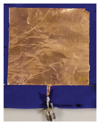
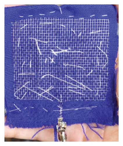
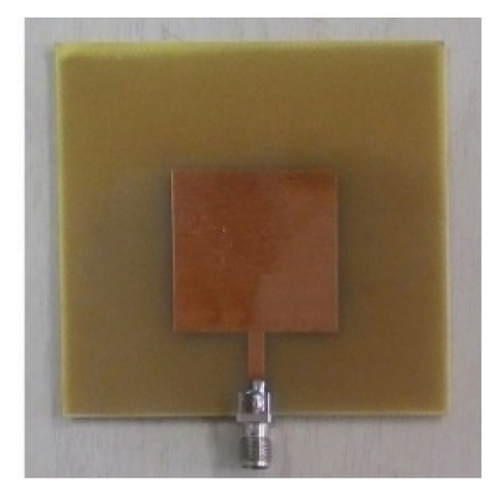
For the glass, paper, and FR4 rectennas, the same materials were used for both the antennas and the rectifier circuits, which were constructed as integrated components. However, for the fabric rectenna, the rectifier circuit was built separately on an FR4 substrate. This approach allows the circuit to be removed for washing and avoids the challenges of integrating electronic circuits directly into the fabric, such as its mechanical flexibility and the absence of a stable, conductive surface.
The selection of materials in this work was guided by a trade-off between efficiency, electrical performance, ease of fabrication, low cost, availability, and suitability for various applications. However, the manual fabrication techniques used to construct the proposed systems can introduce discrepancies between the numerical and physical models, leading to differences between measured and simulated results. In addition, these discrepancies may be further amplified by the variability and uncertainty in the electrical properties of the dielectric materials employed.
3. Material Characterization
The electrical characterization of the dielectric substrate is essential for the design of MPAs, as it directly affects their performance. Parameters such as electrical permittivity (ε) and loss tangent (δ) influence impedance matching, radiation efficiency, and resonant frequency. A well-characterized substrate allows for accurate simulations, optimal signal propagation, and reduced energy loss, improving gain and bandwidth.
Since the dielectric substrates investigated in this work—except for FR4—do not have rigorously defined electrical parameters available in the literature, a characterization methodology is proposed to determine the values of ε and δ. This methodology, referred to here as the reverse characterization process (RCP), consists of three steps.
First, a square MPA is designed for each investigated substrate using a 35-μm-thick copper tape as the radiating element, as illustrated in Figure 2(a). The dimensions Xlin, Ylin, Xan, and Yan are determined through an optimization procedure using the genetic algorithm (GA), adjusted with a population of 32 individuals and a mutation rate of 60%, available in CST software, executed with the time-domain solver. The material properties considered in this step are glass (ε = 4, δ = 0.02, thickness = 2.9 mm), paper (ε = 2, δ = 0.015, thickness = 1.35 mm), polyester fabric (ε = 2, δ = 0.02, thickness = 1.6 mm), and FR4 (ε = 4.3, δ = 0.015, thickness = 1.57 mm). The optimization process aims to achieve high gain and directivity values with S11 < −10 dB.

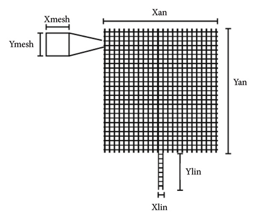
Next, using the obtained dimensions, four antennas—each fabricated with one of the investigated materials—are produced. Their measured S11 parameters, obtained using the VNA Agilent Keysight E7051C, are then compared with the respective simulated results.
Finally, new simulations are performed for each antenna, adjusting the values of ε and δ until convergence between the simulated and measured S11 values is achieved, with the resulting ε and δ values considered as the characterized properties of the respective material. The results obtained by applying the proposed RCP are presented in Table 1.
| Substrate | Final ε | Final δ |
|---|---|---|
| Glass | 6.54 | 0.055 |
| FR4 | 4.15 | 0.015 |
| Polyester | 1.45 | 0.022 |
| Paper | 2.00 | 0.054 |
For the polyester fabric antenna, a new analysis is required to assess the influence of using an IFFM instead of copper tape. To this end, additional simulations using the topology indicated in Figure 2(b) were performed, considering the IFFM mesh gaps Xmesh = Ymesh = 1.5 mm while maintaining the dimensions Xlin, Ylin, Xan, and Yan obtained from the optimization process for the polyester fabric antenna with copper tape. The simulations also used the ε and δ values presented in Table 1. The S11 parameter results obtained from the simulations using IFFM and copper tape showed significant differences. Moreover, the simulation with copper tape took 4 h, whereas the one with IFFM took 96 h, highlighting a substantial increase in computational cost.
To reduce computational effort while still accounting for the effects of the IFFM, a numerical model was developed, using adjusted ε and δ values to capture the differences introduced by substituting the IFFM with copper tape. A prototype of the polyester fabric antenna with IFFM was then constructed, as shown in Figure 1(b), following the same Xlin, Ylin, Xan, and Yan dimensions derived from optimizing the polyester fabric antenna with copper tape. A new S11 parameter measurement was performed, accompanied by further simulations (using copper tape), where the ε and δ values were fine-tuned until convergence between the simulated and measured S11 values was achieved. The resulting ε = 1.15 and δ = 0.024 values were determined to characterize the properties of the polyester fabric antenna with the integrated IFFM.
4. Antenna Design
The topology of an antenna is a key factor in determining the performance of a rectenna system. Alternative rectenna designs have been explored to enhance efficiency and coverage, often incorporating antenna arrays. Performance improvement strategies range from simple configurations, such as 2 × 2 MPA arrays, to more complex arrangements with multiple elements. Considering these factors, along with the specific objectives and constraints of each project, this work proposes various antenna topologies derived from single-element MPAs, incorporating modifications and strategic arrangements to optimize performance.
Maintaining visibility is a key requirement for the glass substrate antenna intended for window applications. A geometry called the glass MPA (GMPA) is proposed to achieve this. The GMPA ensures high visibility because of its central aperture in the radiating element and a ground plane that extends only halfway along the feed line, as illustrated in Figure 3. For the FR4 substrate, MPAs are arranged in pairs, referred to in this work as fiber MPAs (FMPA) (Figure 4). A configuration consisting of four MPAs connected by transmission lines with fixed lengths and variable thicknesses is proposed for the paper substrate, designated as the paper microstrip patch antenna (PMPA), as shown in Figure 5. Lastly, a pine tree–shaped microstrip antenna (PTMA) is selected for the polyester fabric substrate to increase gain while maintaining aesthetic appeal, as illustrated in Figure 6. For PMPA, FMPA, and PMTA, the ground plane covers the entire back face of the antennas.
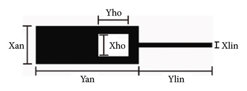
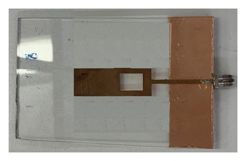
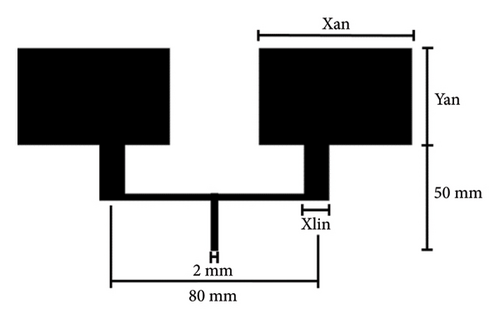
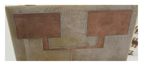

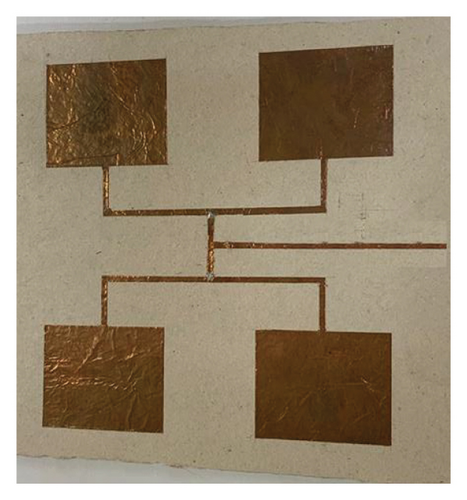
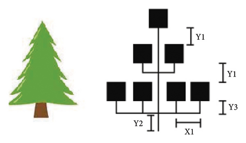

The GA optimization process from CST, configured with the parameters presented in Section 1, was applied to optimize the GMPA, FMPA, PMPA, and PTMA geometries. The ε and δ values used are those listed in Table 1, except for the polyester fabric, which is ε = 1.15 and δ = 0.024. The optimization process aims to achieve high gain and directivity values with S11 < −10 dB at 2.45 GHz. The results presented in Table 2 indicate that the PTMA exhibits the best performance in terms of gain and S11 values. However, based on essential engineering criteria, all antennas are considered operational, as they achieve S11 < −10 dB.
| Parameter | GMPA | PMPA | FMPA | PTMA |
|---|---|---|---|---|
| Xlin (mm) | 30.24 | 2.23 | 8.70 | 4.28 |
| Ylin (mm) | 1.99 | — | — | — |
| Xan (mm) | 42.98 | 47.81 | 51.73 | 57.91 |
| Yan (mm) | 15.80 | 39.21 | 31.23 | 58.81 |
| Xho (mm) | 12.49 | — | — | — |
| Yho (mm) | 9.92 | — | — | — |
| Y1 | — | — | — | 47.00 |
| Y2 | — | — | — | 18.23 |
| Y3 | — | — | — | 35.37 |
| X1 | — | — | — | 99.99 |
| S11 (dB) | −15.45 | −30.02 | −18.78 | −38.79 |
| Gain (dB) | 2.41 | 1.44 | 4.21 | 7.54 |
5. MTM Design
MTMs are artificially engineered structures that exhibit unique electromagnetic properties, enabling precise control over wave propagation [15]. In MPAs, MTMs can enhance gain, bandwidth, and efficiency while also facilitating miniaturization and suppressing of surface waves. Therefore, this work investigates integrating MTM structures into the geometry of the MPA used in the proposed rectennas to enhance their efficiency. To guarantee that this integration yields the desired results, a suitable MTM cell geometry must be carefully selected. MTM cell designs vary widely, including split-ring resonators, complementary structures, and periodic patterns such as square or rectangular arrays. To achieve a simple and easily manufacturable structure for the proposed rectennas, basic MTM cell topologies were selected. Considering this requirement and the advantages of placing MTM cells on the same plane as the radiating element—such as enhanced directivity, improved gain, and a wider operating bandwidth—small rectangular MTM cells [17] were integrated into the GMPA and PMPA antenna structures aligned with the radiating elements, as shown in Figures 7 and 8.

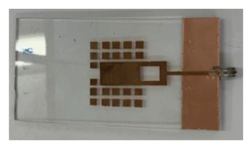
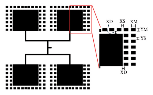

Initially, the MTM cell size was calculated as λg/10, where λg represents the wavelength of the antenna substrate. The dimensions of each MTM cell were then carefully optimized using the GA process in CST, with the configuration parameters described in Section 1. This optimization process also accounted for the antenna dimensions and the spacing between the cells and the antenna to minimize the S11 parameter and improve the operating bandwidth. The resulting data are presented in Table 3.
| Dimensions (mm) | GMPA | PMPA | FMPA |
|---|---|---|---|
| Xlin | 29.86 | 2.54 | 8.70 |
| Xan | 41.72 | 47.01 | 51.73 |
| Yan | 15.14 | 39.81 | 31.23 |
| XM | 4.89 | 5.83 | 0.75 |
| YM | 4.77 | 5.61 | 6/7 |
| YS1/YS | 2.89 | 3.92 | 6.1/7.1 |
| YS2 | 8.83 | — | — |
| XD | 2.93 | 3.02 | — |
| XS | 3.97 | 2.98 | 6 |
| YD | 2.95 | — | — |
For the FMPA, an alternative method of integrating the MTM structure into the MPA was investigated. In this case, the MTM structure was positioned in front of the antenna’s radiating element, acting as a lens to focus the electromagnetic waves, thereby increasing the antenna’s directivity and enhancing its gain [18]. The final configuration comprises six rows of MTM cells comprising two distinct types. The four inner rows are populated with longer cells (Type 1), while the two outer rows feature shorter cells (Type 2), as shown in Figure 9(a). Initially, the size of the MTM cells was calculated as λg/10. Subsequently, the dimensions shown in Figure 9(a) were optimized using the same GA technique while the FMPA’s original dimensions remained unchanged. The results obtained are presented in Table 3.
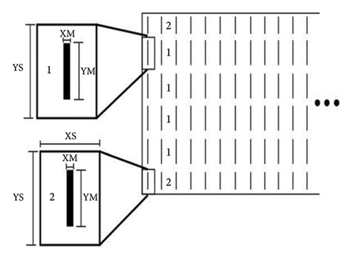
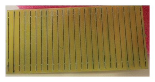
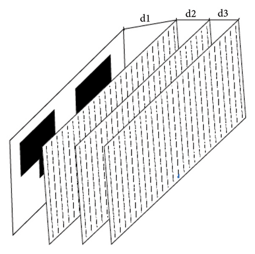
Three MTM boards were fabricated to assess the performance of the proposed MTM lens, enabling an evaluation of each lens’s individual contributions to the system (Figures 9(b) and 9(c)). The distances between each MTM lens and the antenna were optimized to achieve the optimal configuration, with the resulting values of d1 = 4.51 mm, d2 = 11.01 mm, and d3 = 10.9 mm.
A key distinction between the applied methodologies lies in their influence on the antenna’s radiation pattern. When MTM cells are placed on the same surface as the radiating element, their primary effect is modifying the radiation pattern, which may also shift the operating frequency. In contrast, the second approach focuses on shaping and directing electromagnetic waves toward the receiver antenna, providing greater flexibility and making it applicable to antennas of various shapes and configurations.
6. Rectifier Circuit
Rectenna systems experience significant losses because of the rectification process and impedance mismatches between the antenna and rectifier. This work adopts a VDRC to address these challenges. This topology is particularly advantageous for rectennas because of its simplicity and ability to effectively boost output voltage levels. It is well-suited for low-power applications, such as electromagnetic energy harvesting. The proposed VDRC employs a Schottky diode (HSMS 2852) and two 100 μF capacitors (Figure 10). In addition, an impedance-matching network consisting of a stub (S1) and two transmission lines (TL1 and TL2), as illustrated in Figure 11, is incorporated to achieve proper impedance matching with the respective antennas (50 Ω), thereby maximizing power transfer efficiency.
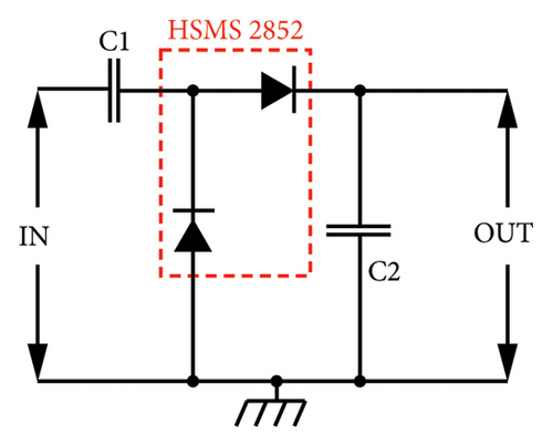
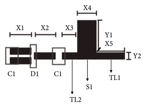
The same VDRC circuit topology was implemented for all rectennas investigated in this work. The circuit trace dimensions were optimized using the GA technique available in the ADS. Efficiency was evaluated with a load of 1MΩ and an input power of −10 dBm. The primary optimization objectives were to minimize the S11 parameter within the 2.3–2.5 GHz frequency range while maximizing energy conversion efficiency. The optimization variables included the dimensions X1, X2, X3, X4, X5, Y1, and Y2, with the final optimized values presented in Table 4.
| Dimensions (mm) | Glass | Paper | FR4 |
|---|---|---|---|
| X1 | 5.0 | 5.0 | 5.0 |
| X2 | 4.0 | 2.6 | 3.4 |
| X3 | 3.0 | 4.9 | 4.9 |
| X4 | 5.0 | 3.5 | 5.0 |
| X5 | 13.0 | 8.8 | 8.9 |
| Y1 | 11.0 | 6.0 | 9.5 |
| Y2 | 2.0 | 2.6 | 2.6 |
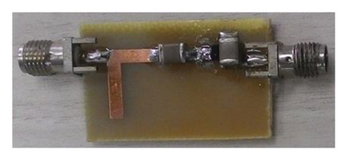
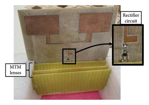
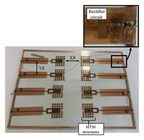
For the PTMA, a standalone VDRC was designed on a separate FR4 substrate with two SMA 3011 connectors, allowing for easy connection and disconnection from both the antenna and the load, as illustrated in Figure 12. In contrast, for the glass, paper, and FR4 substrates, the VDRC was integrated directly into the antenna structure, as shown in Figures 13, 14, 15.
7. Rectenna Array
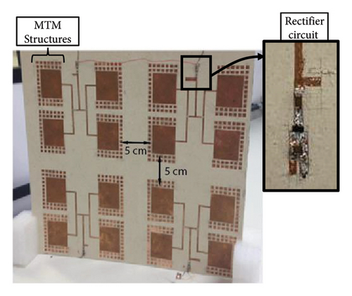
Multiple rectennas can be interconnected in series or parallel to achieve higher voltage levels at the load, forming a rectenna array [19]. In this study, the parallel configuration was selected and applied to both glass and paper substrates. Specifically, eight antennas and rectifiers were arranged for the glass substrate array with a vertical spacing of 8 cm and a horizontal spacing of 4.5 cm, corresponding to the XR and YR parameters, respectively, as shown in Figure 13 [12]. For the paper substrate, a 2 × 2 array configuration with a 5 cm spacing between rectennas was implemented, as illustrated in Figure 15.
8. Numerical and Experimental Results
The numerical and experimental evaluation conducted in this work examined the individual components (antennas and rectifiers) of each proposed rectenna and the operation of the entire system. The evaluated parameters include the S11 parameter, measured using the Agilent Keysight E7051C VNA, the voltage across the load, and the efficiency of the rectifier circuit.
8.1. Antennas
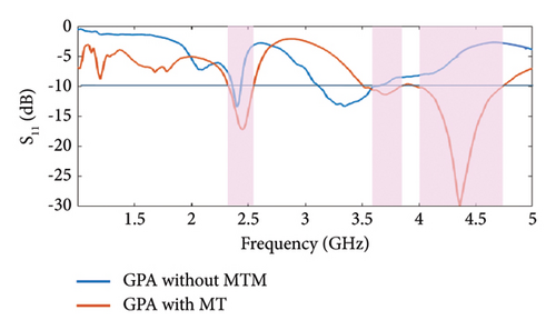
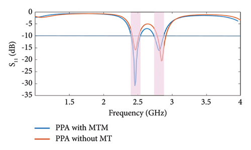
For the experimental evaluation of the MPA, S11 values were analyzed. Figure 16 presents the results for the GMPA, both without (Figure 3) and with MTM (Figure 7). As observed, the inclusion of MTM broadened the bandwidth and reduced the S11 value. In addition, the simulated antenna gain increased from 2.42 to 4.51 dB after integrating MTM structures. The results for the PMPA are shown in Figure 17. Similar to the GMPA, including MTM improved the S11 parameter without significantly altering the bandwidth (PMPA in Figure 5 and PMPA with MTM in Figure 8). The simulated gain for the antennas with MTM cells increased from 1.44 to 5.01 dB, demonstrating the effectiveness of the MTM integration. For both antennas, a good correlation between numerical and experimental results was achieved, particularly at the design frequency, further validating the effectiveness of the proposed design. In addition, the prototypes with MTM exhibited functionality at an additional frequency beyond the design frequency.
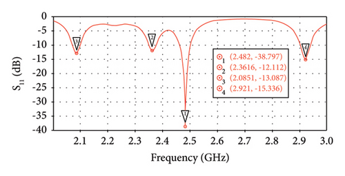
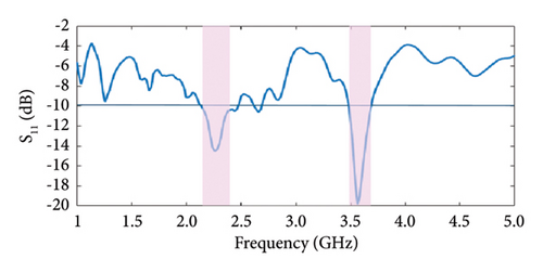
The results obtained for the PTMA are presented in Figure 18. As observed, the constructed antenna effectively operated at two distinct frequency bands, notably 2.3 and 3.5 GHz, highlighting its broad bandwidth capabilities. Specifically, at the target frequency of 2.45 GHz, the numerical and experimental results exhibited good agreement, meeting the established optimization criteria. The discrepancies between simulations and measurements can be attributed to uncertainties introduced by the manual fabrication process, which inherently has lower precision for this antenna, as well as to approximations proposed in the electrical characterization of the polyester fabric when incorporating the IFFM.
Lastly, Figure 19 presents the measured and simulated results for the FMPA. In this case, a broader frequency range was evaluated, as the antenna exhibited multiband operation at 1.7, 2.45, 6.0, and 7.9 GHz. Once again, the experimental results showed good agreement with the numerical data, particularly at the design frequency, while the optimization requirements were successfully met.
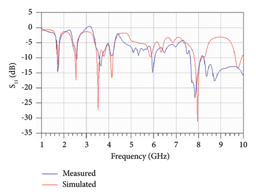
The numerical and experimental results of the four types of MPA proposed in this study showed good agreement. This confirms the validity of both the proposed material characterization process and the construction method employed.
8.2. Rectifier Circuit
Before being integrated into their respective antennas, a separate prototype of each, as presented in Section 6, was constructed to enable independent experimental evaluation. The obtained efficiency results and S11 parameter values are shown in Table 5. It can be observed that the measured values were worse than the simulated ones, which is expected because of the limitations of the manual construction process. However, all DVRCs are operational at design frequency (S11 < −10 dBm). Efficiency values were calculated by measuring the injected power into the rectifier circuit using the Keysight N5181A signal generator set to deliver −10 dBm at 2.45 GHz and by assessing the output active power under a resistive load of 1 MΩ.
| Parameters at 2.45 GHz and −10 dBm | Glass | FR4∗ | FR4∗∗ | Paper |
|---|---|---|---|---|
| S11 simulated (dB) | −29.12 | −24.90 | −26.18 | −24.59 |
| S11 measured (dB) | −23.05 | −11.41 | −19.15 | −17.41 |
| η Simulated (%) | 16.0 | 29.1 | 18.5 | 30.7 |
| η Measured (%) | 0.14 | 0.12 | 0.13 | 0.10 |
- ∗DVRC for FMPF.
- ∗∗DVRC for PTMA.
8.3. Rectennas
The setup shown in Figure 20 was used to evaluate the proposed rectenna systems. The rectennas were positioned at a variable distance, D, from a single-element FR4 MPa, powered by the Keysight N5181A signal generator configured to operate at 2.45 GHz with a power output of 30 dBm. Since the rectennas were placed in the far-field region of the transmitting antenna, approximately 5 cm away, they operated with electromagnetic waves in the transverse electromagnetic (TEM) mode.
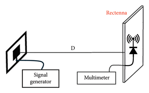
To determine the optimal load values for each rectenna, a potentiometer was connected to the parallel combination of the rectifier circuits for the glass and paper rectennas and to the output of the single rectifier in the FR4 and polyester fabric rectennas. Maximum power transfer was achieved with load values of 5.2 and 30 kΩ for the glass and paper rectennas and 10 and 50 kΩ for the FR4 and polyester fabric rectennas, respectively.
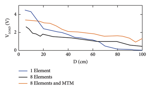
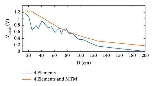
For the glass and paper rectennas, the results obtained, presented in Figures 21 and 22, respectively, demonstrate that the system with MTM structures yielded higher voltage values. For the FR4 rectenna, the inclusion of 0–3 MTM lenses positioned at distances d1 = 4.51 mm, d2 = 11.01 mm, and d3 = 10.9 mm was evaluated, as shown in Figures 9(c) and 13. The system was placed 10 cm away from the transmitting antenna, and the voltage was measured across a load of 10 kΩ. The results in Table 6 indicate that adding a single MTM cell initially led to a slight degradation in performance. However, with the inclusion of two cells, the output voltage nearly doubled, and with three cells, the improvement reached 2.5 times the original signal. In addition, the FMPA gain was numerically evaluated, confirming a progressive increase in gain with each additional MTM surface, reinforcing the effectiveness of the MTM integration.
| Test | Simulated gain (dB) | S11 Antenna (dB) | Vout (mV) | |
|---|---|---|---|---|
| Measured | Simulated | |||
| 0 MTM | 4.21 | −10.37 | −18.78 | 100 |
| 1 MTM | 4.51 | −9.40 | −25.28 | 80 |
| 2 MTM | 6.17 | −11.53 | −16.86 | 200 |
| 3 MTM | 7.23 | −11.98 | −11.78 | 250 |
The output voltage results for the polyester fabric rectenna are presented in Table 7, demonstrating the system’s functionality. However, the lower voltage values observed reflect the higher losses associated with the fabric substrate and mechanical flexibility, which can lead to impedance mismatches and variations in performance. Despite these limitations, the rectenna remains operational.
| D (cm) | 5 | 10 | 20 | 30 |
| Vout (mV) | 72 | 55 | 43 | 29 |
9. Conclusion
This study investigates four rectenna topologies designed on various substrates. The results obtained validate the effectiveness of the proposed systems and confirm their operational functionality. Furthermore, the inclusion of MTM cells has been demonstrated to enhance efficiency. In addition, glass-based models yielded superior results to wallpaper-based models, suggesting their potential application for building facades or residential settings. Conversely, wallpaper rectennas could be considered a decorative element for residential or commercial interiors. It was also observed that increasing the number of associated antennas leads to improved gain characteristics, as evidenced by the fabric models. However, while more rectenna systems offer better performance over longer distances, they also incur higher production costs because of the cost of components such as diodes. The simulations and constructions presented in this study have validated the hypothesis of developing efficient functional rectenna systems on unconventional substrates [16].
Conflicts of Interest
The authors declare no conflicts of interest.
Funding
The authors thank the Brazilian National Council for Scientific and Technological Development (CNPq), the Minas Gerais State Agency for Research and Development (FAPEMIG), the Brazilian Federal Agency for Support and Evaluation of Graduate Education (CAPES), and the Federal Center for Technological Education of Minas Gerais (CEFET-MG) for funding this work under the grants 402785/2023-1 and APQ-01473-24.
Acknowledgments
The authors thank the Brazilian National Council for Scientific and Technological Development (CNPq), the Minas Gerais State Agency for Research and Development (FAPEMIG), the Brazilian Federal Agency for Support and Evaluation of Graduate Education (CAPES), and the Federal Center for Technological Education of Minas Gerais (CEFET-MG) for funding this work under the grants 402785/2023-1 and APQ-01473-24.
Open Research
Data Availability Statement
All data generated or analyzed during this study are included in this article.


