Four-Element UWB MIMO Antenna System With a Square Frame Decoupling Structure for Enhanced Isolation and Polarization Diversity Characteristics
Abstract
In this study, we introduce a cost-effective antenna designed for ultrawideband (UWB) spectrum. The antenna employs a single-layer coplanar waveguide (CPW) feed on a 1.6 mm FR4 board. Notably, the antenna demonstrates a bandwidth from 3.7 to 15.7 GHz (12 GHz) for a single element. Expanding its utility, a four-element Multiple Input Multiple Output (MIMO) assembly is arranged orthogonally, aiming to achieve diversity characteristics. The MIMO elements are connected through a common ground plane. In the MIMO configuration, the bandwidth response is increased to 2.9–16.2 GHz. To mitigate mutual coupling between the antenna elements, a simple geometric parasitic element is inserted between them, resulting in a significant improvement of 15 dB in isolation. In addition, a maximum gain of 5.5 dBi is noted at 14 GHz with total efficiency exceeding 80% throughout the resonance bandwidth. The individual antenna element boasts a compact footprint of 20 × 26 mm2, while the MIMO configuration occupies an area of 46 × 48 mm2. Furthermore, we conduct a thorough analysis of various MIMO performance metrics, including the envelope correlation coefficient (ECC), mean effective gain (MEG), and diversity gain (DG), all of which fall within acceptable thresholds. These analyses validate the potential of our proposed UWB–MIMO antenna for diverse UWB applications.
1. Introduction
For biomedical applications such as microwave imaging, antennas are required to have consistent radiation. Ultrawideband (UWB) technology effectively fulfills these conditions. Compact planar structures are highly preferred due to their size compatibility with integration into microwave imaging and RF systems [1, 2]. UWB antennas, introduced here, are pivotal tools in communication equipment, offering a plethora of services [3, 4]. UWB antennas have a wide frequency range, which is essential for wireless communication and radar systems [5, 6]. Their broad bandwidth allows for fast and efficient data transfer, perfect for wireless USB, streaming, and fast file sharing. They also have precise timing, useful for tracking objects indoors and outdoors, aiding in asset tracking, navigation, and healthcare monitoring. Adding Multiple Input Multiple Output (MIMO) technology boosts UWB systems by improving data speed, capacity, and reliability [7]. MIMO helps by using multiple antennas to reduce signal interference and improve coverage [8, 9]. It can transmit multiple data streams simultaneously and handle signal challenges better through smart signal processing. This combination of UWB and MIMO is crucial for modern communication, offering faster data rates, wider coverage, and stronger performance [10].
In the literature, several UWB systems have been addressed [11–18]. In [11], a four-element leaf-shaped planar UWB MIMO system is presented with dimensions of 55 × 55 mm2. The ground layout is optimized to ensure good impedance matching. Simulations demonstrate 13.2 GHz bandwidth and 3.5 dBi gain. To enhance isolation, a fan-shaped decoupler was inserted at the back, achieving 18 dB isolation. In [12], a UWB MIMO antenna is presented with 14 dB coupling and a physical size of 40 × 40 mm2. The is noted < 0.4. In [13], a four-port rectangular monopole MIMO system is discussed. The UWB response of the proposed design is achieved by employing etching on the backside and creating an arrow-shaped slot on the front patch. Notably, the antenna exhibits an isolation of 17 dB among its radiating elements, while possessing total physical dimensions of 80 × 80 mm2. Similarly, in [14, 15], UWB systems with orthogonal arrangements are presented with bandwidth covering 3.4 to almost 13.5 GHz. A connected ground plane is crucial for maintaining a common ground voltage between ports in MIMO systems. This common ground voltage reference ensures that all antenna elements operate at the same electrical potential, preventing potential differences between elements that could lead to signal distortion or interference. Without a connected ground plane, each antenna element might have its own ground reference, leading to variations in ground potential across the antenna array. These variations can result in signal distortion, impedance mismatches, and increased mutual coupling between elements. The abovediscussed literature mainly consisted of MIMO systems with separate ground planes. In [16], a four-port MIMO system featuring a UWB (3.1–10.6 GHz) response is introduced. The antenna design incorporates a modified circular top and rectangular bottom-shaped patch, along with an inverted C-shaped partial ground plane. Utilizing an orthogonal arrangement that combines the ground plane of all ground elements, the system achieves a minimum isolation response of 15 dB with a gain variation of 2.9 dB throughout the bandwidth. Similarly, in [17], a four-port UWB exhibits 123% bandwidth (3.1–13.3 GHz) with a peak gain of 4.0. The ground planes are connected via an extremely thin modified plus-shaped isolator that connects all ground planes via the center.
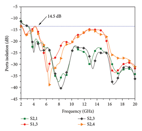
In this research, a UWB MIMO Antenna System with a connected ground plane, enhanced isolation, and high gain is presented. The antenna system is simple in structure, generating high bandwidth characteristics from 3.7 to 15.7 GHz with a minimum isolation of at least 14.5 dB across all resonating elements. The proposed system offers better performance characteristics as per reported literature and hence can be considered a suitable candidate for UWB, microwave, and imaging applications. The paper is organized as follows: Section 1 includes the thorough literature discussion, followed by Section 2, in which the detailed working mechanism of single element and MIMO configuration is discussed. Section 3 provides findings obtained from the measured prototype. Section 4 covers MIMO performance characteristics, followed by the conclusion.
2. Antenna Design
2.1. Single Element
Before explaining the MIMO system mechanism, the evolution and working principle of the single element structure alongside its performance parameters are discussed. The proposed antenna is designed using CPW feeding since these transmission lines exhibit low dispersion characteristics, making them more suitable for high-speed digital and analog signal transmission applications. Figure 1 depicts the proposed UWB antenna on FR4 board with a permittivity of 4.4. Table 1 provides complete details of the physical dimensions of the proposed structure. The design features a straightforward patch structure with a CPW ground plane.
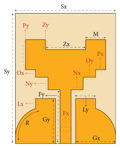
| Par. | R | Sx | Sy | Zx | Zy | M | Ox | Oy | Gx |
|---|---|---|---|---|---|---|---|---|---|
| Value | 15 | 20 | 26 | 8 | 2 | 4 | 1.5 | 2.5 | 8 |
| Par. | Ly | Px | Py | Nx | Ny | Fx | Fy | Lx | Gy |
| Value | 4 | 2 | 6 | 2.5 | 2.5 | 2.2 | 10.75 | 2 | 9 |
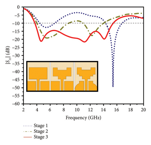
The patch has been altered with staircase-like steps and a rectangular slot positioned at the top-middle section. Likewise, the ground plane has been transformed into a semishark fin shape with a connecting staircase, aimed at achieving wideband resonance. This can be understood by looking at Figure 2, which showcases the design evolution and |S11| of the evolution stages. The design evolved across three distinct stages: Stage 1, Stage 2, and the proposed Stage 3. Initially, the design featured a simple rectangular patch integrated with a CPW waveguide configuration. This configuration yielded notable dual-band resonance, with lower resonance occurring at 5.5 GHz and upper resonance at 15 GHz. Building upon this foundation, Stage 2 introduced a refinement by incorporating rectangular slots along the bottom edges and the top middle section of the patch. This alteration broadened the operational bandwidth from 4.2 to 8.5 GHz in the lower and 11 to 14 GHz in upper spectrum. In the proposed Stage 3, further enhancements were introduced to augment the performance characteristics of the design. Notably, the bottom edges were subjected to additional modifications, now featuring an arrangement of rectangular slots that assumed a staircase-like formation. Concurrently, a transformation was applied to half of the ground plane on each side, reshaping it into what was termed a “shark fin” configuration, resulting in the desired UWB characteristic.
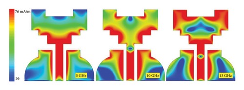
The surface current patterns are depicted in Figure 3 at 5, 10, and 13 GHz. Analyzing these patterns reveals a distinct behavior: at lower frequencies, the currents primarily concentrate around the lower edges of the rectangular slots. However, as the frequency increases, a noticeable shift occurs. At higher frequencies, current induction is observed not only at the top and bottom edges but also across the ground plane. This transition in current distribution highlights the dynamic nature of the structure’s electromagnetic response across different resonances.
2.2. MIMO Configuration
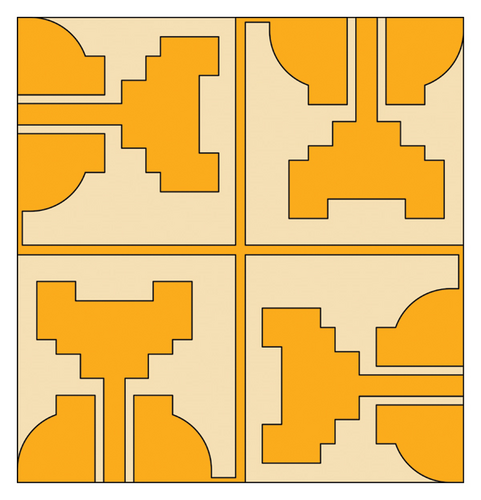
The UWB antenna after finalizing is set to four element MIMO form to enhance wireless communication by enabling simultaneous data transmission and reception across multiple spatial streams. The MIMO arrangements are arranged in orthogonal manner to provide pattern as well as polarization diversity characteristics. The polarization diversity configuration for proposed MIMO system is adopted since it provides better mitigation of multi-path fading and signal degradation in complex environments. A MIMO antenna system with vertical and horizontal polarization elements improves signal reception and transmission by capturing and transmitting signals in multiple polarization planes. This reduces the likelihood of signal degradation due to multipath fading, as signals reflected and scattered by obstacles may change polarization.
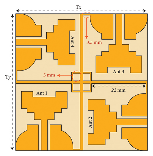
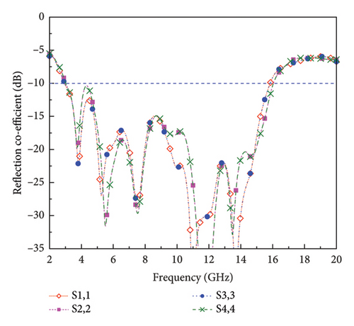
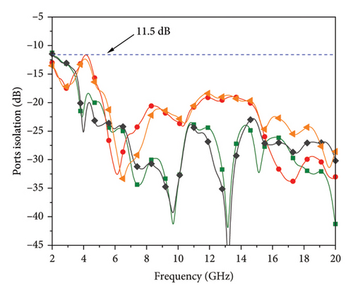
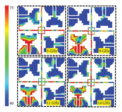
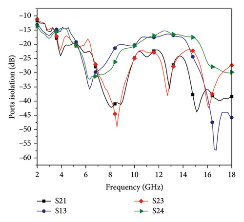
By having both vertically and horizontally polarized antennas, the system can better maintain signal quality and strength, leading to enhanced reliability with good overall performance in diversified dynamic environment. Figure 4 describes the layout of the proposed MIMO structure. The MIMO structure is incorporated with a decoupling network that connects the ground plane of all resonating elements via the edges. This small connection also contributes to shifting the lower resonance back from 3.7 to 2.9 GHz. The isolating structure initially consisted of two strip lines intersecting in the middle of each other, forming a plus shape. To improve isolation between face-to-face elements (1–3, 2–4), a square frame was inserted, which enhanced isolation among both radiating elements. This effect can be clearly seen by looking at the S-parameters response in Figure 5. The effectiveness of the isolating structure can be assessed by examining the surface current patterns (Figure 6). The currents within all resonating bandwidths are concentrated around the isolating structure, with minimal interaction between individual elements. This indicates that the isolating structure effectively reduces mutual coupling, leading to better performance.
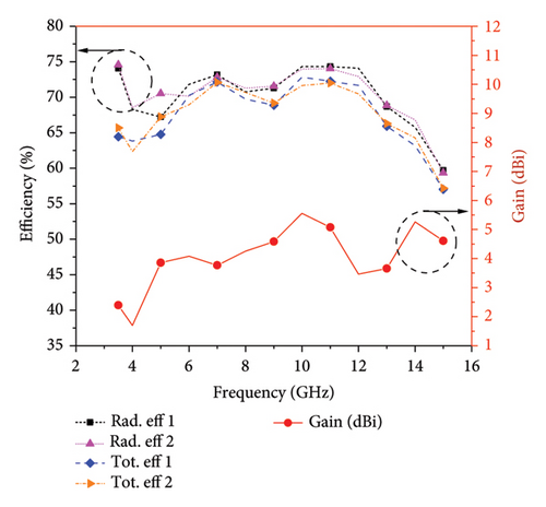
The efficiency along with the gain of the proposed MIMO system are shown in Figure 7. The radiation efficiency shows value from 59% and 73%, while the maximum gain is noted to be 5.5 dBi at 10 and 14 GHz. This demonstrates that the proposed MIMO antenna system not only achieves good isolation but also maintains high radiation efficiency and significant gain across the UWB spectrum, making it suitable for high performance. At 12 GHz, the gain shows a noticeable dip, which can be attributed to several factors. One possible reason is destructive interference in the radiation pattern, leading to a temporary reduction in the antenna’s directivity. In addition, the efficiency curves (both radiation and total efficiency) remain relatively stable in this region, suggesting that the drop in gain is more likely due to pattern distortion rather than increased losses. This could result from the excitation of higher-order modes or a shift in the current distribution, causing reduced constructive radiation in the main lobe direction. Such variations are common in broadband antennas, where certain frequencies experience changes in radiation characteristics due to resonant interactions or structural discontinuities.
2.3. Equivalent Circuit
2.3.1. Single Element
The modeling of the proposed CPW antenna into a lumped RLC circuit provides a sense of understanding the antenna’s working behavior from the circuit theory perspective. The modeling also aids in comprehending maximum power transfer from source to load antenna, which has to be a complex conjugate of source impedance. Generally, a resonance of the TM01 mode patch antenna is represented by a parallel RLC circuit. However, the proposed antenna is CPW, and as a result, the coupling capacitance effect between the feed lines (CFL) and ground plane and between patch and ground plane (CPG) has to be considered while modeling the RLC circuit. The equivalent RLC circuit of the proposed single-element antenna is shown in Figure 8(a) and its impedance network in Figure 8(b).
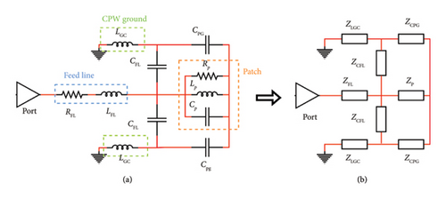
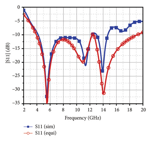
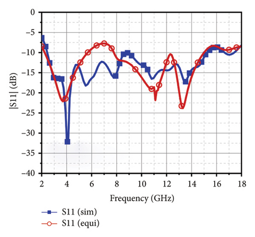
Table 2 shows the equivalent circuit RLC values. The significance of capacitance CPG in the circuit is that the resonance frequency decreases as its value increases and vice versa. It means that the distance between the edges of ground plane and patch first step structure is crucial in determining the antenna’s resonance. On the other hand, the capacitance CFL aids in improving the impedance matching between the feed line and the antenna such that the maximum power is transferred from the port to the radiating patch. In the context of antenna design, the slot width in CPW determines the impedance matching. At 4.66 GHz, the impedance of ZFL, ZLGC, ZCPG, and ZP are 37, 11.711, 162.71, and 32.97 Ω. The overall impedance can be calculated by applying delta-to-start and vise-versa conversion for the impedance circuit. The tuned circuit values have demonstrated the closest S11 curve to the simulated results in Figure 9.
| Parameter | Values |
|---|---|
| RFL | 37 |
| LGC | 0.4 |
| CFL | 0.23 |
| LP | 0.95 |
| LPP | 1 |
| LF | 0.89 |
| CF | 0.49 |
| LFL | 0.19 |
| CPG | 0.21 |
| RP | 100 |
| CP | 0.25 |
| LB | 0.3 |
| CS | 0.43 |
2.3.2. MIMO Antenna
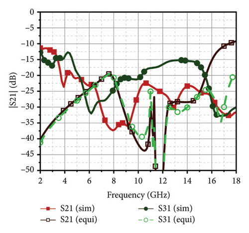
The abovementioned equivalent circuit is expanded to a four-element form, as seen through Figure 10. The equivalent circuit of the single-element antenna is replicated for the abovementioned four-port MIMO antenna. The decoupling structure in the design has a plus shape inside a square box, for which the strip line is extended from four edges to the ground of each antenna. This is modeled as an inductance in the circuit, where LB represents the decoupling structure square box with a plus sign by LP inductance. The gap in the structure is modeled as capacitance CB. The extending strip line is represented as LF, and the spacing of this line adjacent to an antenna is CS and opposite by CF. The desired isolation between the elements is achieved by tuning these values while maintaining the |S11|, as shown in Figure 11.

3. Results and Discussion
To check the simulated performance of the antenna, a vector network analyzer (VNA) was used. The actual antenna prototype is shown in Figure 12. For far-field radiation characteristics measurement at selected frequencies, a shielded room using a far-field measurement setup was used. After measurements, the simulated and measured outcomes were evaluated.
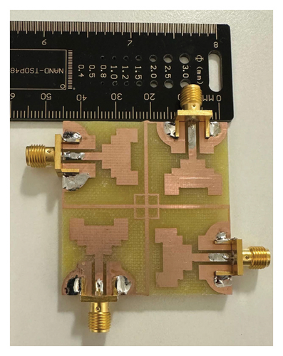
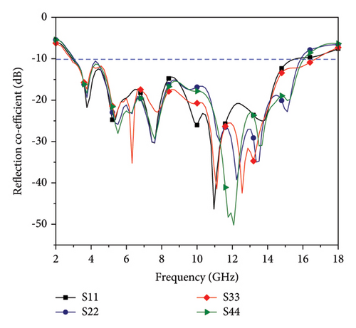
Figure 13(a) shows the measured reflection coefficients, while Figure 13(b) displays the transmission coefficients. These figures clearly indicate that the measured responses of both reflection and transmission coefficients align well with the simulated data presented in Figure 5. The impedance bandwidth, spanning 13.1 GHz (2.95–15.5 GHz), indicates that the antenna can operate efficiently across a wide range of frequencies, making it suitable for UWB applications. The measured isolation at −15 dB demonstrates that the antenna elements are effectively decoupled, minimizing mutual interference and ensuring reliable performance. The minor discrepancies among findings are common in practical measurements due to factors such as fabrication tolerances, material inconsistencies, and slight variations in the measurement environment. Despite these differences, the overall agreement validates the antenna design’s robustness and effectiveness.
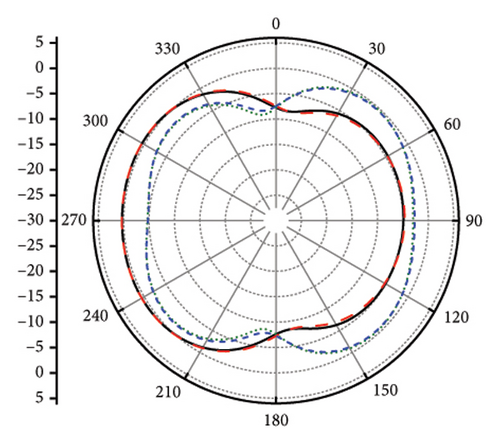
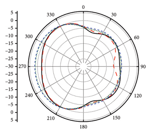
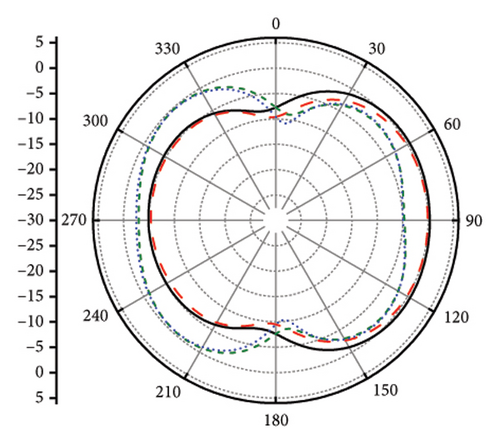
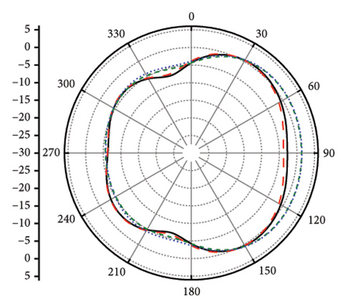
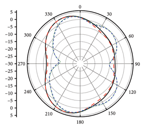
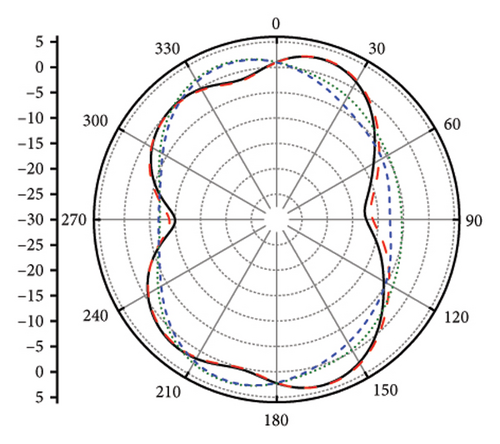
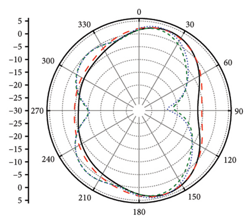
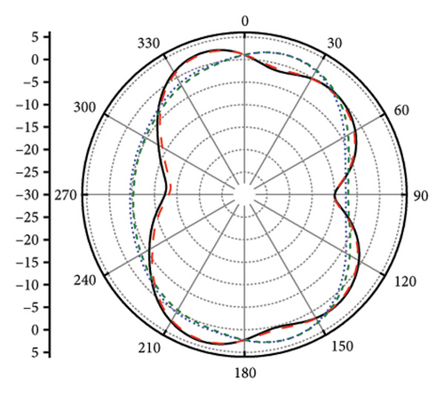
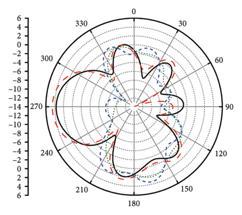
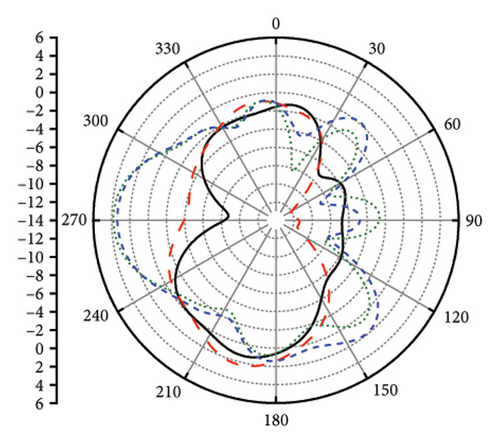
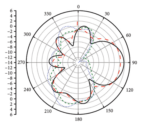
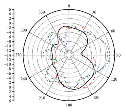
The radiation pattern analysis of the proposed MIMO system is shown in the following figures. Due to the orthogonal arrangement of the structure, the antenna provides pattern and polarization diversity characteristics. The radiation patterns at 5, 9, and 13 GHz have been presented for all resonating elements at ϕ = 0° and ϕ = 90°. At 5 GHz, the radiation patterns for Ant 1 and Ant 2 are primarily directed toward 270°, indicating a broadside radiation pattern. For Ant 3 and Ant 4, the patterns are directed toward 90°, showing the opposite radiation direction due to their orthogonal placement. This configuration provides pattern diversity, which helps in better signal reception and transmission by covering multiple directions. At 9 GHz, Ant 1 and Ant 3 exhibit similar but opposite radiation patterns, which means that the energy is radiated in opposite directions, enhancing spatial coverage and reducing interference. Ant 2 and Ant 4 show butterfly-shaped radiation patterns, indicating a dual-lobe pattern that can cover a wider area and provide polarization diversity, as the orthogonal arrangement allows the antennas to respond differently to signals with varying polarization. At 13 GHz, the radiation patterns become quasidirectional with more focused beams. Ant 1 and Ant 3 continue to show similar but opposite characteristics, while Ant 2 and Ant 4 display similar yet opposite behavior. This indicates that at higher frequencies, the antenna elements maintain their diverse radiation patterns, ensuring effective coverage and reliable communication links. The face-to-face configuration in the same plane but opposite directions further enhances the isolation by minimizing unwanted coupling and optimizing the radiation characteristics. The solid black lines represent ϕ = 0 (Simulated), dashed red lines represent ϕ = 0 (Measured), short dash blue lines represent ϕ = 90 (Simulated), and short dot green lines represent ϕ = 90 (Measured) in Figures 14, 15, and 16.
3.1. MIMO Parameters
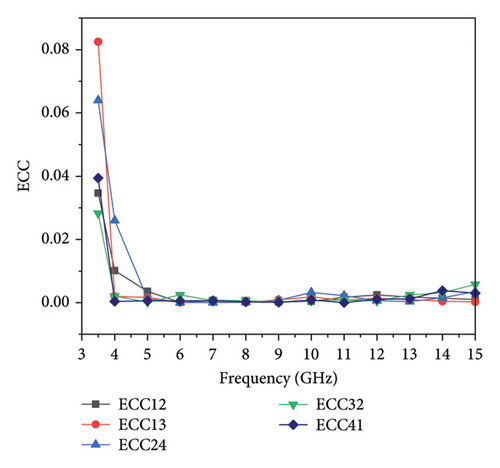
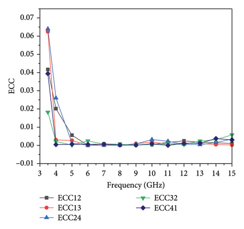
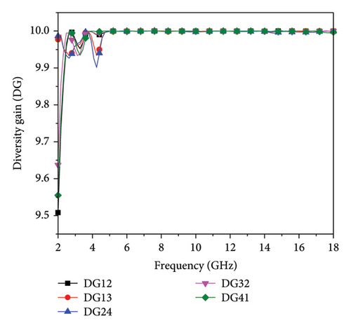
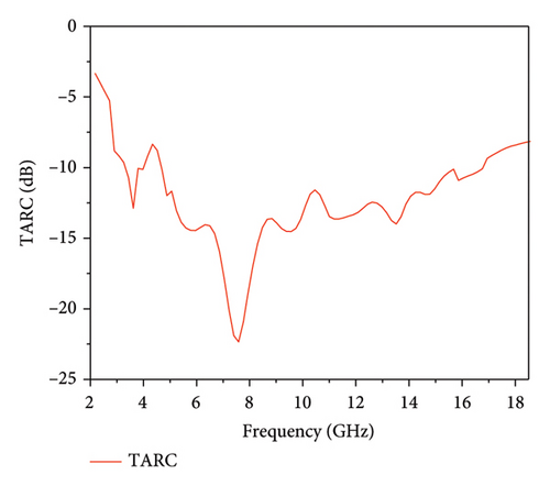
All the MIMO parameters are presented in Figures 17(a), 17(b), 17(c), and 17(d). The ECC values for the adjacent element and diagonal element are illustrated in Figures 17(a) and 17(b). The proposed antenna design aims for an ECC below 0.003, as indicated in the figure, across operational bandwidth for both nearby and diagonal elements. In MIMO systems, where diversity schemes are employed, there are inherent losses in transmission power that need to be accounted for. These losses are typically analyzed through DG. The ideal scenario aims for a DG of precisely 10 dB, indicating optimal performance. However, in real-world scenarios, achieving this exact value is often impractical due to various environmental factors and system limitations. As such, values close to 10 dB are generally considered acceptable benchmarks for performance evaluation. Figure 17(c) showcases a DG of ≈ 9.99 dB across entire frequency band. This performance is indicative of the antenna’s capability to mitigate the effects of fading and enhance signal reliability in diverse propagation environments. Similarly, the TARC calculated (Figure 17(d)) shows well satisfactory limits. MEG in wireless communication systems represents average power gain over all possible directions. It accounts for variations in gain across different angles, providing a comprehensive measure of antenna efficiency. MEG is crucial for assessing the overall effectiveness of an antenna in transmitting or receiving signals in various real-world scenarios, making it a fundamental parameter in antenna design and deployment. The proposed MIMO system’s MEG values are shown in Table 3, which are in well limits in the operating range.
| Freq. (GHz) | MEG 1 | MEG 2 | MEG 3 | MEG 4 |
|---|---|---|---|---|
| 3.5 | −4.02 | −4.31 | −4.05 | −3.99 |
| 5 | −4.01 | −4.32 | −4.55 | −4.19 |
| 7 | −4.01 | −4.33 | −4.22 | −4.44 |
| 9 | −4.11 | −4.21 | −4.35 | −4.32 |
| 13 | −4.11 | −4.22 | −4.55 | −4.15 |
In the comparative analysis between the proposed MIMO antenna system and existing four-element MIMO literature in Table 4, it becomes evident that the proposed antenna system excels in various performance metrics. It offers enhanced bandwidth, superior gain, and acceptable MIMO parameters while with connected ground plane. This evaluation shows the effectiveness and efficiency of the MIMO system proposed for modern communication systems.
| Ref | Size (mm2) | B.W (GHz) | Sij (dB) | Gain | ECC |
|---|---|---|---|---|---|
| 12 | 40 × 40 | 3–13.5 | < 14 | 6 | < 0.05 |
| 13 | 80 × 80 | 2–11 | < 17.4 | 3.3 | < 0.03 |
| 14 | 40 × 40 | 2.9–13.6 | < 15 | 5.5 | < 0.04 |
| 15 | 47 × 47 | 37–11 | < 14 | 3.5 | < 0.1 |
| 16 | 40 × 40 | 3.1–10.6 | < 16 | 2.9 | < 0.01 |
| 17 | 45 × 47 | 3.1–13.1 | < 16 | 4.0 | < 0.01 |
| 22 | 40 × 40 | 3.2–14.4 | < 22 | 4.9 | < 0.01 |
| 23 | 40 × 40 | 3.2–13.4 | < 20 | 2.0 | < 0.02 |
| 24 | 55 × 55 | 3.2–20 | < 16 | 6.1 | < 0.01 |
| 25 | 65 × 65 | 2.9–10.86 | < 22 | 7 | < 0.01 |
| 26 | 58 × 58 | 3.1–4.2 | < 15 | 4 | < 0.001 |
| 27 | 48 × 48 | 4.5–5.25/6–7 | < 14 | 4.5 | < 0.02 |
| Prop. | 46 × 48 | 2.9–16.2 | < 14.5 | 5.5 | < 0.04 |
4. Conclusion
This research introduces a novel 4 × 4 MIMO antenna system for UWB applications. Leveraging a modified CPW-fed slotted radiating patch, the individual antenna elements exhibit operating frequency range of 3.7–16.2 GHz and achieving a peak gain of 5.5 dBi. Furthermore, the seamless integration of these elements into a cohesive 4 × 4 MIMO array, accompanied by a connected ground plane, demonstrates exceptional performance for UWB MIMO scenarios. Through considerate design modifications, including orthogonal arrangement to facilitate pattern and polarization diversity, the array showcases an impressive impedance bandwidth spanning from 2.9 to 16.2 GHz. Notably, effective isolation levels (< 14.5 dB) are achieved with the insertion of simple isolating structure between antenna elements to ensure minimal interference, further enhancing the systems reliability and suitability for complex UWB communication environments [22–27].
Conflicts of Interest
The authors declare no conflicts of interest.
Funding
The authors sincerely appreciate funding from Researchers Supporting Project number (RSP2025R58), King Saud University, Riyadh, Saudi Arabia. The authors would like to thank for the support by the National Nature Science Foundation of China (Grant no. 62174148), National Key Research and Development Program (NKRDP Grant no. 2022YFE0112000), and Key Program for International Joint Research of Henan Province (Grant no. 231111520300).
Open Research
Data Availability Statement
The data used to support the findings of this study are included within the article.


