Shape Adjustment of a Large Planar Phased Array Antenna With Nonlinear Cable Actuators
Abstract
Shape adjustment of large planar phased array antennas is significant because the shape distortion of phased arrays can greatly reduce the antenna’s gain in the observing direction. This study selects the inherent diagonal cables driven by motors as actuators, initially used to improve the stiffness of the antenna structure. The shape adjustment can be implemented by changing the length of the diagonal cables, so that there is no need to design additional control devices, which can significantly reduce the mass and improve the reliability of the antenna system. For shape adjustment, the cable tensions are chosen as the control inputs in general, but for structures with finite deformations, the cable tensions may be strongly coupled and therefore can no longer be used as the control inputs. We examine all the sources of the elongation of the cable actuator and group them into three categories: pre-elongation, passive elongation, and feedback elongation. Since the feedback elongations of different cables are driven independently by the motors and do not change with the structural deformation, they can be used as the control inputs. Giving a detailed theoretical derivation, this paper demonstrates the necessity of considering nonlinearity of the cable actuator and proposes a nonlinear model of the active cable element. Further, an optimization model is established for shape adjustment, and the genetic algorithm is used to solve this problem. The effectiveness of the proposed nonlinear active cable element and the shape adjustment method is validated by simulations. Results show that the shape adjustment can be successfully achieved by the nonlinear cable actuators proposed in this paper. Moreover, the effect of pre-elongation on the stiffness of the antenna structure can be well reflected by the nonlinear cable actuators, and the relationship between the shape adjustment and the number of actuators is also investigated.
1. Introduction
Recently, phased array antennas have been widely used in high-resolution Earth observation and ground-moving target identification and tracking [1–3]. A phased array antenna arranges many radiators on its array panels and utilizes phased shifters to adjust the phase of the electromagnetic wave emitted by each radiator, thus achieving the beam steering [4]. Compared with the traditional mechanical scanning reflector antennas, phased array antennas are lightweight, fast scanning, and highly reliable, so they are widely used as satellite-borne antennas [5–7]. For the tasks of Earth observation and ground-moving target identification and tracking, medium Earth orbit (MEO) satellites and geostationary Earth orbit (GEO) satellites are more suitable [8, 9]. First of all, in order to realize observation and tracking, the antennas need to stare at the object over a long period of time (several seconds), which is difficult for the low Earth orbit (LEO) satellites due to their high velocity relative to the Earth’s surface [10]. Secondly, LEO satellites own a relatively small field of view; thus, realizing continuous global coverage requires about 100 LEO satellites, which is prohibitive. At last, MEO satellites are bathed in sunlight for almost the entire orbital period, but LEO satellites spend nearly half of their orbital period in darkness. That means LEO satellites must carry many batteries to operate when solar power is not available, again making LEO satellites less desirable. According to the basic theory of antennas [11–14], the azimuth resolution is roughly equal to the slant range multiplied by the azimuth beamwidth, that is, Rλ/L, where R is the slant range, λ is the wavelength, and L is the horizontal length of the antenna. Thus, we need to increase the antenna size in proportion to the track height to maintain a high resolution. However, the application of large-scale antenna also raises new issues, and one of the very prominent problems is the severe influence of the distortion of the phased arrays on the electrical performance of the antenna [15]. Since the radiators are arranged on the phased array panels, the shape distortion of the antenna may change the direction of the wave beams or even destroy the coherence of the wave beams. For the small-size antennas, the stiffness is relatively large, and the deformation of the phased arrays is very small so that the electrical compensation is enough to ensure the antennas’ high gain and pointing accuracy, while for the large-scale antennas, the deformation of phased arrays may be finite thus cannot be ignored; it is necessary to introduce the mechanical compensation to adjust the shape of the antennas and then use the electrical compensation for further wave beam adjustment [16]. Therefore, the shape adjustment of large-scale phased array antennas is a critical issue.
To achieve the shape adjustment and vibration control of large-scale phased array antennas, researchers have used various forms of actuators, such as piezoceramic (PZT) actuators, shape memory alloy actuators, and magnetostrictive actuators for antenna shape adjustment and vibration control, and have achieved high surface accuracy. In [17–20], several different active cable structures incorporating the PZT actuator in flexible cable were proposed to achieve shape adjustment of antennas. In some research [21, 22], an electrothermomechanical model of the shape memory alloy was presented, and the shape memory cable-net structure was proven to be able to improve the in-orbit surface accuracy of the cable-net antenna. However, it is known that the output displacement of PZT actuators is limited, so PZT actuators are not suitable for controlling large structures with a finite deformation. Furthermore, the shape memory alloy actuators are sensitive to temperature, and the magnetostrictive actuators are susceptible to electromagnetic interference. Therefore, the above actuator types are unsuitable for achieving shape adjustment for large planar phased array antenna. In fact, it is unwise to pursue the antenna’s high surface accuracy by purely using mechanical compensation; instead, it is more reasonable to use the mechanical compensation to adjust the antenna shape to a certain accuracy and then introduce the electrical compensation for fine regulation of the wave beam. In this way, there is no need to add additional control devices; instead, the inherent diagonal cables of the antenna structure, which are used to improve the structural stiffness, can be directly utilized as the actuators. Using the motor-driven variable-length cables as actuators will significantly reduce the mass and cost of the antenna system and improve the reliability of the antenna structure [23].
The modelling of active cable driven by the motor has received attention over the years. In [24–28], systems composed of cables, pulleys, other rigid bodies, and a motor were modelled by the absolute nodal coordinate formulation (ANCF) or arbitrary Lagrangian–Eulerian (ALE) formulation, in these researches, active cables were treated as variable-length cables driven by a motor. In other research [29–31], the effects of the active cables were considered control forces. Although these studies have dealt with the modelling of active cables, they are still not suitable for shape adjustment and vibration control; the reasons are discussed below. For the deployment of antennas, a cable–pulley system driven by a motor is widely used, but for shape adjustment and vibration control, the situation is somewhat different. In structural control problems, a number of independent drive motors and the corresponding active cables are used without pulleys. It is also inappropriate to take the tensions of the active cables as the control inputs of the system. In the process of adjusting a finite deformation structure, the magnitude and the direction of the cable tensions are constantly changing with the structure, and the tensions of different active cables are coupled. Suppose that there are two cables used as actuators, the current tension of Cable #1 is 20 N, and the current tension of Cable #2 is 30 N. If the calculation results of a certain control algorithm show that they need to reach 100 N to eliminate the structural deformation, then, to control the structure, we can start from Cable #1 by adjusting its tension from 20 to 100 N. However, when the tension of Cable #1 reaches 100 N, the configuration of the structure has been changed; therefore, the tension of Cable #2 is no longer 30 N, may be 40 N or other value. In the same way, when we then adjust the tension of Cable #2 to 100 N, the tension of Cable #1, which was previously set to 100 N, also changes in response to the structure’s deformation. For a system with only two actuators, perhaps, we can gradually adjust the tensions of the two cables to their final target value by an iterative method. However, for an antenna system with many actuators, the coupling between the cable tensions will bring substantial difficulties.
- 1.
In traditional shape adjustment, the tensions of the active cables are used as the control inputs. However, for a structure with a finite deformation, the tensions of different cables may be coupled. To solve this problem, we carefully examine the sources of the length change of the active cable and group the sources into three categories: pre-elongation, passive elongation, and feedback elongation. Among them, the feedback elongations of the cables are entirely determined by the drive motors and do not change with the deformation of the structure. Thus, we choose the feedback elongations as the control inputs to avoid the coupling between the control inputs. Compared to the traditional method of using the tensions of the active cables as the control inputs, the method proposed in this paper has great advantages in dealing with structures with a finite deformation.
- 2.
For controlling a structure with a finite deformation, the elongations of the active cables may be large so that the nonlinear effect of the cables must be taken into account. This paper, with detailed theoretical derivation, demonstrates the rationality of ignoring the cubic term and retaining the quadratic term in the expression of cable tension and provides the specific expression for the nonlinear tension of the cable. In this way, the structural model can accurately reflect the enhancement of the stiffness by the pre-elongation, making the calculation results more accurate. If the nonlinearity of the cable is not considered, the structure’s stiffness will remain constant and have no relationship with the elongation of the active cables, which is very inconsistent with the actual physical situation.
The remainder of this paper is organized as follows. Section 2 describes the research object and the problem to be solved in detail. Section 3 establishes the active cable element model based on the finite element method and obtains the structural model of the whole antenna. Section 4 proposes an antenna shape control scheme which transforms the shape adjustment problem into an optimization problem. Section 5 conducts the numerical simulations. Finally, the conclusions of the study are drawn in Section 6.
2. Description of the Research Problem
The phased array antenna structure studied in our research is depicted in this part. As shown in Figure 1, the antenna comprises the collecting box, support truss, and phased array feed panel assembly. The antenna’s configuration and the local amplification of the antenna are both depicted in Figure 1, and as can be seen, the antenna consists of numerous identical bays connected end to end.

The support truss and the phased array feed panel assembly are bundled and kept in the collecting box prior to the satellite launch. Once the spacecraft has entered its intended orbit, three lead screw guide rails are unfolded and locked into position for sequential antenna bay deployment. The outermost bays are first deployed along the three guide rails, which start with the heating of the longerons. The longerons are made of a kind of shape memory alloy material that could deform into the designed shape under specific temperatures. The diagonal cables and phased array panels deploy with the antenna bay to which they are attached. Once the outermost bay is deployed, the heaters on that bay are powered off, and that bay is allowed to cool while the next bay is warmed up. The next bay pushes the previous bay off the guide rails until the antenna is completely deployed [1]. The deployment process of each bay is generally elucidated in Figure 2. During the antenna deployment, all the cables are in a slack state, but after the deployment, all cables are tensioned according to their predesigned values. For graphical simplicity, the diagonal cables are not drawn in Figure 2(a).
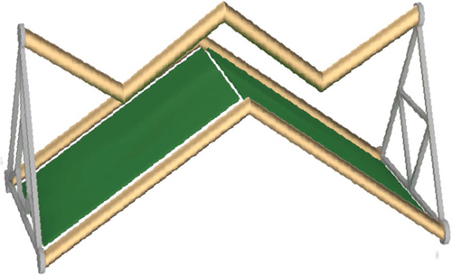
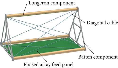
Figure 2(b) shows the structure of a typical deployed bay, which includes one phased array feed panel, three longeron components, and six batten components. In order to strengthen the stability and rigidity of the bay, batten components are formed into a triangular configuration. For the same reason, additional connecting beams are purposefully inserted inside the triangle structure. Longeron components, along with batten components, comprise the antenna’s triangular prism structure. The feed panels of phased arrays are hinged to the batten elements, and the inherent diagonal cables are set up as shown in Figure 2(b). It is known that the relative displacements of the feed panels along the antenna will reduce the coherence of the antenna arrays, so they need to be removed. Actually, the relative displacements may be caused by the antenna structure twisting or bending as a result of slewing actions or as a result of temperature gradients. To ensure the antenna’s performance, we need to modify the static shape of the antenna by some control methods. In practice, it is common to employ a truss with several intrinsic cables for large-scale space structures like mesh antennas, massive planar antennas, and enormous space station solar panels. In general, these cables are pretensioned and are only utilized to preserve the structural integrity or improve the rigidity of structures. However, in our study, these inherent cables will be used as actuators to avoid adding additional control devices. Considering that improper adjustment methods may cause dynamics problems, during the actual control process, we make sure that drive motors rotate at a very slow speed to avoid dynamics problems. In this way, the shape adjustment process can be regarded as a quasistatic process.
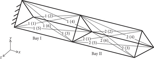
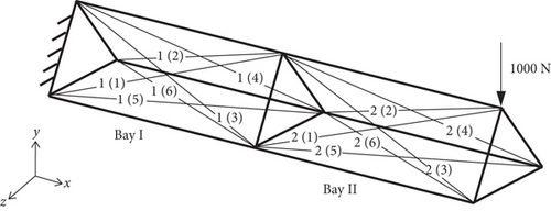
It is necessary to point out that there are predesigned clearances between the suspension hinges and the feed panels, as well as between neighboring feed panels. As a result, when deformation is not too great, the feed panels will not participate in resisting deformation and will not contribute to the structural stiffness of the antenna. Therefore, the phased array antenna can be accurately adjusted, provided we are able to control the deformation of its support truss successfully. In this way, the challenge of adjusting the static shape of the phased array antenna can be translated into the problem of adjusting the static shape of the support truss. Hence, this paper only deals with the simplified antenna without feed panels. A simplified two-bay antenna with the left end fixed to the satellite and the right end free is shown in Figure 3. Each bay contains six diagonal cables. For simplicity and clarity in our discussion, we number the diagonal cables in this simplified antenna in the form of p(q), where p denotes the bay to which the cable belongs and q denotes the orientation of the cable. Taking the two-bay antenna as an example, Figure 3 illustrates the numbering rules for the cables.
3. Structural Finite Element Modelling
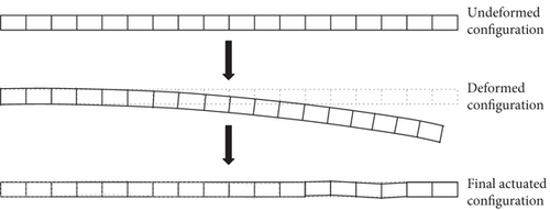
To begin our discussion, we need to introduce some assumptions first. For an antenna with a large axial size, finite deformation is difficult to avoid. But even though the antenna as a whole undergoes a finite deformation, for each bay of the antenna, the strain is quite limited. So, for the diagonal cables in each bay, their strains are still small despite the large displacements and rotations. Based on this consideration, we employed the Saint Venant–Kirchhoff material model for cable simulation in our paper [35]. Moreover, since only the case of ground experiments is considered in this paper and the main aim is to verify the effectiveness of the shape adjustment method proposed in this paper, the external loads to which the antenna is subjected are given. Furthermore, although the structure may undergo a finite deformation, the final controlled configuration should be very close to the ideal undeformed configuration, which is just the purpose of shape adjustment. Taking the bending deformation of an 18-bay antenna as an example, the undeformed configuration, the deformed configuration under load, and the final actuated configuration of the antenna are shown in Figure 4. The purpose of the antenna shape control is to maintain its shape accuracy, so that each radiator of the antenna array can reach the designed position, that is, where they are located in the undeformed configuration of the antenna, so the final actuated configuration of the antenna must be very close to the initial undeformed configuration, otherwise the electrical performance of the antenna cannot be guaranteed. In practice, when the antenna structure is adjusted from the deformed configuration to the final actuated configuration, although the final actuated configuration cannot be completely returned to the initial undeformed configuration, the difference between the two is already very small, as shown in Figure 4. At last, we need to point out that the tension is uniform in all different parts of the cable.
- 1.
The strain of each cable is small but not infinitesimal.
- 2.
The material of the cable is isotropic and elastic, and the Saint Venant–Kirchhoff material model is used here.
- 3.
The external loads are given, so we do not need to estimate them using the measurement data.
- 4.
As the finite deformation of the antenna structure must be controlled successfully, we assume that the final controlled equilibrium configuration of the antenna is close to the initial undeformed configuration.
- 5.
The tension of the cable is uniform, which means that for the exposed part of the cable and the part that is rolled into the drive motor, the tension is the same.
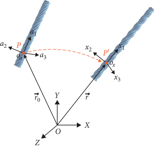
After introducing the basic assumptions of our study, we also need to clarify some concepts. As shown in Figure 5, there are two configurations of the cable: the undeformed configuration and the deformed one. Three Cartesian coordinate systems are introduced to define the stress and the strain accurately. One is the spatial coordinate system OXYZ, which is also called Eulerian coordinates. The other two Oaa1a2a3 and Oxx1x2x3 are material coordinates or Lagrangian coordinates, which are attached to the undeformed configuration and the deformed configuration, respectively. The position vector of any particle in the undeformed configuration with respect to the spatial coordinate system is denoted as r0, and that of the deformed configuration is denoted as r.
3.1. Active Cable Element
3.2. Beam Element
3.3. Coordinate Transformation and Assembly of Elements
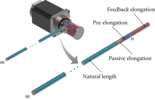
This is exactly the equilibrium equation of the antenna structure, which contains the active cable element. In Equation (35), the global stiffness matrix K is a function of the active elongation of the active cable element, so as the vector of additional nodal forces Fadd which is caused by the active elongation. Based on Equation (35), we can achieve the shape adjustment by changing the length of the active cable element. Before our discussion of the next section, we want to say more about the active elongation of the cable. As has been mentioned, the active elongation of a cable element consists of two parts: one is the pre-elongation, and the other is the feedback elongation. With respect to the pre-elongation, it is designed to improve the stiffness of the antenna structure and applied to the structure by the deployment of the antenna. As we know, each diagonal cable has its natural length, while after deployment, when the antenna reaches its design configuration, each cable is longer than its natural length; all these diagonal cables are tensioned. In other words, all these cables are preloaded. As for the feedback elongation, it is designed to achieve shape adjustment, and its magnitude is determined by the structural deformation. The most important difference between the pre-elongation and the feedback elongation may be that the pre-elongation is determined before the launch of the satellite and remains unchanged after deployment, while the feedback elongation is adaptive adjusted, the determination of the feedback elongation is based on the deformation of the deployed antenna.
4. Control Scheme
In this part, we will present a control scheme to achieve the shape adjustment and discuss it in detail.
4.1. The Design Variables
4.2. Objective Function
The goal of the shape adjustment is to find a solution for the actuator placement and the feedback elongation to minimize the objective function J(ν, μ).
4.3. Constraints
4.3.1. Constraints of the Actuator Placement
4.3.2. Constraints of the Number of Actuators
4.3.3. Constraints of the Cable Length
4.4. Optimization Algorithm
From the above, we can know that the problem to be solved in this paper is an optimization problem under the above constraints. The design variables are the diagonal matrix ν which denotes the placement of actuators and the vector μ which denotes the feedback elongation of the diagonal cables. The value of the elements of ν can only take 0 or 1, while the value of the elements of μ is continuous, so the optimization problem has mixed discrete–continuous variables with discrete variables corresponding to actuator placement and continuous variables associated with the feedback elongation. If we put the discrete and continuous variables into the same design space, the solution to the problem will be difficult to obtain as the number of variables increases, and the divergence of the iterative process may even occur. Based on the above considerations, a layered optimization strategy is implemented to address this optimization problem with discrete–continuous design variables [37, 38]. In the following, we will introduce the idea of the layered optimization algorithm and then give the solution procedure.
4.4.1. Layered Optimization
The layered structure contains two layers, the outside layer and the inside layer. For a given number of actuators, the outside layer gives the optimal actuator placement and the inside layer gives the optimal feedback elongation. In the outside layer, the genetic algorithm is employed to give the optimal actuator placement; the genetic algorithm produces the initial population which satisfies the constraint on the number of actuators and passes the information about the actuator placement to the inside layer. At this moment, the objective function cannot be obtained since the optimal feedback elongations have not been determined. When the inside layer receives the information about the actuator placement from the outside layer, considering that in Equation (40), u is a nonlinear function of the feedback elongation and the objective function shown in Equation (41) has a quadratic form, then the optimization problem of the inside layer becomes a nonlinear least squares problem with only continuous variable μ. In this way, we can call the lsqnonlin algorithm of MATLAB to get the value of the optimal feedback elongation and the corresponding objective function. Once the inside layer has obtained the value of the objective function, it can pass the information about the objective function to the outside layer, so that for each individual in the initial population of the genetic algorithm, we can obtain the value of the objective function, and the genetic algorithm can run on.
4.4.2. Computational Procedure
- Step 1.
The outside layer generates a set of random actuator placements; each individual corresponds to an actuator placement.
- Step 2.
For each actuator placement given by the outside layer, the inside layer gives the corresponding optimal feedback elongations and returns them to the outside layer.
- Step 3.
Using the optimal feedback elongations given by the inside layer, the outside layer calculates the value of the fitness function of each individual.
- Step 4.
Determine whether the termination condition is satisfied; if yes, the algorithm ends and gives the optimal actuator placement and feedback elongation, otherwise, the genetic algorithm gives a new generation and goes back to Step 2.
It should be noted that since algorithms are not the focus of this paper, both the genetic algorithm and the nonlinear least squares algorithm are implemented by calling existing programs in MATLAB.
5. Numerical Simulations
In this section, we will first perform a simulation of a two-bay antenna support truss to verify the structural model and the control scheme proposed in this paper. In addition, we will introduce an 18-bay antenna support truss to investigate the effect of pre-elongation of the diagonal cables on the structural response. Moreover, the relationship between the control performance and the number of actuators will be studied using the 18-bay antenna support truss model. The material properties and geometric parameters of the antenna structure are given in Table 1. Considering that the computational scale of the iterative method may be extremely large, the genetic algorithm is used in both Simulations 5.1 and 5.3 to determine the optimal actuator placement. The basic parameters of the genetic algorithm are given in Table 2, the other parameters adopt the default values.
| Item | Longeron | Batten | Cable |
|---|---|---|---|
| Young’s modulus | 131 GPa | 370 GPa | 88 GPa |
| Poisson’s ratio | 0.33 | 0.22 | 0.3 |
| Cross-section | Pipe | Box | Circular |
| Outside dimension/outside diameter | 60 mm | 50 × 10 mm | — |
| Inside dimension/inside diam | 58 mm | 48 × 8 mm | 1 mm |
| Length/natural length | 2 m | 1 m | 2.2 m |
| Parameter | Type or value |
|---|---|
| Population size | 100 |
| Population initial range | [0, 1] |
| Selection | Stochastic uniform |
| Crossover fraction | 0.8 |
| Mutation fraction | 0.2 |
| Elite count | 2 |
- Note: Reproduced from Zhou et al. [39].
5.1. Method Validation Based on a Two-Bay Antenna Support Truss
As shown in Figure 7, a two-bay antenna support truss is studied in this part. Its left end is fixed, and the right end is free. To verify that the method is valid not only for small deformation but also for finite deformation, we set the load in the simulation to be larger than the actual situation. A concentrated force of magnitude 1000 N in the negative direction along the y-axis is applied to the top vertex of the free end. Herein, we set the pre-elongation of the cables to 5 cm; the lower bound and the upper bound of the feedback elongation are 0 and 20 cm, respectively.
Using the above conditions, we can establish a structural model and calculate the displacement response under the external forces. Based on the structural model and control scheme proposed in this paper, the shape adjustment is performed for the two-bay antenna support truss. For the two-bay antenna support truss, there are 12 diagonal cables that can be chosen as actuators; we begin with 1 and increase the number of actuators to 12 step by step. As the number of actuators increases, the control performance of the structure is listed in Table 3.
| Number of actuators | Serial number | (cm) | |
|---|---|---|---|
| 1 | 2(4) | 2.8458 | 40.13% |
| 2 | 1(4),2(3) | 1.2239 | 17.26% |
| 3 | 1(4),2(3),2(4) | 0.8953 | 12.62% |
| 4 | 1(3),1(4),2(3),2(4) | 0.0753 | 1.06% |
| 5 | 1(3),1(4),2(2),2(3),2(4) | 0.0753 | 1.06% |
| 6 | 1(1),1(3),1(4),2(2),2(3),2(4) | 0.0753 | 1.06% |
| 7 | 1(1),1(3),1(4),1(5),1(6),2(3),2(4) | 0.0753 | 1.06% |
| 8 | 1(3),1(4),2(1),2(2),2(3),2(4),2(5),2(6) | 0.0753 | 1.06% |
| 9 | 1(2),1(3),1(4),1(5),1(6),2(1),2(2),2(3),2(4) | 0.0753 | 1.06% |
| 10 | 1(1),1(2),1(3),1(4),1(5),1(6),2(3),2(4),2(5),2(6) | 0.0753 | 1.06% |
| 11 | 1(1),1(2),1(3),1(4),1(5),1(6),2(2),2(3),2(4),2(5),2(6) | 0.0753 | 1.06% |
| 12 | 1(1),1(2),1(3),1(4),1(5),1(6),2(1),2(2),2(3),2(4),2(5),2(6) | 0.0753 | 1.06% |
In order to visualize the control performance, we introduce the absolute value of the ratio of the maximum controlled nodal displacement to the initial uncontrolled maximum nodal displacement. In Table 3, the maximum controlled nodal displacement is denoted as , and the maximum uncontrolled nodal displacement is denoted by . In the case of Table 3, equals to 7.0917 cm. Table 3 shows that in the beginning, the control performance improves rapidly as the number of actuators increases. However, once the number of actuators exceeds four, the control performance no longer gets better anymore. From Table 3, we can see that when the number of actuators exceeds four, there are always four diagonal cables that will be selected as actuators, and their serial numbers are 1(3), 1(4), 2(3), and 2(4). In fact, according to the optimization results, when the number of actuators exceeds four, the feedback elongation of all the diagonal cables selected as actuators is equal to zero except for the four diagonal cables above. This means that, under the conditions of this simulation experiment, using Diagonal Cables 1(3), 1(4), 2(3), and 2(4) as actuators is already the optimal solution for actuator placement. To further analyze this result, we highlighted the positions of these four diagonal cables in the two-bay antenna support truss, as shown in Figure 8.
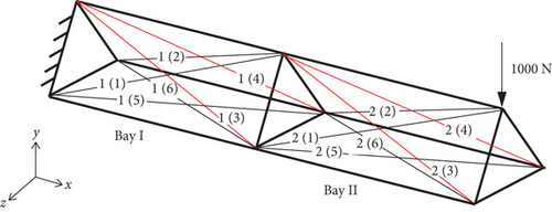
In fact, even if we do not do any theoretical calculations for this two-bay antenna support truss, just based on the symmetry of the structure and the loads, we can easily determine the optimal actuator placement according to the fundamental physics, which are exactly the four cables indicated in Figure 8. Our knowledge of fundamental physics also allows us to conclude that, except for the four diagonal cables chosen as actuators, the remaining cables have no effect on reducing the deformation of the structure under the given conditions (the lower limit of the feedback elongation equals zero, so that the Diagonal Cables 1(1), 1(2), 2(1), and 2(2) do not work). The fact that the optimal actuator placement determined by the fundamental physics is in perfect agreement with the results calculated by the optimization program proves the correctness of the structural model and the control scheme proposed in this paper.
To demonstrate the necessity of considering the nonlinearity of the cable element, we calculated the feedback elongation of the diagonal cables when only linearity is considered, then compared it with the optimization results of nonlinear diagonal cables; the results are listed in Table 4.
| Serial number | Linear feedback elongation (cm) | Nonlinear feedback elongation (cm) |
|---|---|---|
| 1(3) | 4.25 | 3.89 |
| 1(4) | 4.25 | 3.89 |
| 2(3) | 4.35 | 3.98 |
| 2(4) | 4.35 | 3.98 |
From Table 4, we can see that the feedback elongation is symmetric about the xy-plane for both the linear cables and the nonlinear cables. This is because the object studied here has a symmetric structure, and the external load is in the symmetric plane. Therefore, its deformation is symmetric, and the feedback elongation controlling this deformation should naturally be symmetric as well. Additionally, as observed in Table 4, the feedback elongation of the linear cable is greater than that of the nonlinear cable. This can be explained by the fact that the strain in the nonlinear cable contains nonlinear terms, enabling the nonlinear cable to generate a larger control force than the linear cable for the same feedback elongation. In other words, compared to linear cables, nonlinear cables can control the same deformation with smaller feedback elongations. Finally, the results in Table 4 show that the linear feedback elongation is approximately 10% larger than the nonlinear feedback elongation and cannot be ignored, emphasizing the importance of considering nonlinearity for controlling finite structural deformations.
In terms of actuator placement, the simulation results are fully consistent with the conclusions drawn from the fundamental physics. Regarding feedback elongations, the nonlinear cables exhibit smaller feedback elongation due to the inclusion of the nonlinear terms of strain. Furthermore, on the subject of control performance, the controlled maximum nodal displacement is about 1% of the uncontrolled maximum nodal displacement. All these results confirm that the structural model established and the control scheme proposed in this paper are accurate and effective.
5.2. Effect of the Pre-Elongation
Figure 9 shows an 18-bay antenna support truss, which is studied to analyze the effect of pre-elongation on structures. In this simulation, the left end of the 18-bay antenna support truss is fixed, and the right end is free. For a large antenna, the deformation is obvious, and according to our research [2], out-of-plane bending is the main deformation form of the antenna during its orbital period. To generate an obvious out-of-plane bending deformation, a concentrated force of magnitude 1500 N in the negative direction along the y-axis is applied to the top vertex of the free end.
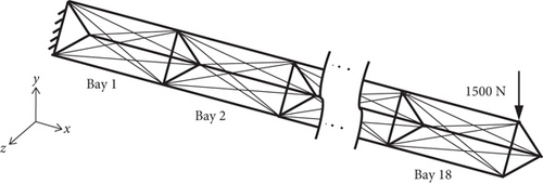
To study the effect of pre-elongation on the structural response, we gradually increase the pre-elongation and observe the change in the maximum nodal displacement of the antenna structure. Considering that the diagonal cables cannot be slackened and the pre-elongation cannot exceed the maximum allowable elongation of the cables, we set the value range of the pre-elongation between 5 and 25 cm.
The relationship of the pre-elongation and the maximum nodal displacement is shown in Figure 10.
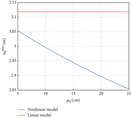
The result curves are distinguished by different colors. The blue curve represents the result of the nonlinear model, where the nonlinearity of cables is taken into account, while the red curve represents the result of the linear model, where the nonlinearity of cables is not considered. Analysis of Figure 10 reveals that for the nonlinear model, the maximum nodal displacements of the structure gradually decrease as the pre-elongation increases. This finding indicates that the model considering the nonlinearity of the cables is able to reflect that the pre-elongation plays a role in improving the stiffness of the structure. In contrast, if the nonlinearity of cables is not taken into account, the result corresponds to the red curve in Figure 10. The red curve shows that for the linear model, the pre-elongation does not have any effect on the stiffness of the structure, which is inconsistent with physical facts. It is necessary to point out that the maximum nodal displacement presented in Figure 10 is only a rough approximation since only the nonlinearities of the cables are considered here, but the nonlinearities of the structure are not taken into account. In fact, when the size of a structure is extremely large, the geometric nonlinearity can have a significant impact on the stiffness of the structure. In summary, compared with the traditional linear cable element, the nonlinear active cable element proposed in this paper can reflect the physical facts more accurately and thus is very important.
5.3. Effect of the Number of Actuators
In this part, we aim to study the effect of the number of actuators on the shape adjustment of the antenna and attempt to determine the optimal number of actuators for the typical loading cases given in the simulation. We need to point out that for different types of deformation (bending, twisting, or complicated deformation), the optimal actuator number and positions are different. Therefore, the optimal actuator number and positions obtained in this simulation are not applicable to all load cases. In the future, if we have enough experimental data of space antennas from which we can analyze the main forms of antenna deformation in space, we can use the method of this paper to determine the optimal actuator number and positions. The 18-bay antenna shown in Figure 9 is studied here again; the boundary conditions and the loads are the same as in the above simulation. In this simulation, the pre-elongation is set to 5 cm, and the lower and upper bounds of the feedback elongation are 0 and 20 cm, respectively. We gradually increase the number of actuators and use the control scheme proposed in this paper to solve the optimal actuator placement and the corresponding control inputs that satisfy the constraints. In this simulation, the advantage of genetic algorithm is obvious; if the number of actuators is p, then for 108 optional positions, the number of possible actuator placement is ; at this time, the conventional optimization algorithms will be ineffective, and the genetic algorithms can be a good solution to this problem. Using the genetic algorithm, the relationship between the maximum controlled nodal displacement and the number of actuators is shown in Figure 11.
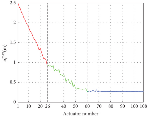
From Figure 11, we can see that as the number of actuators increases, the maximum controlled nodal displacement decreases, and the maximum controlled nodal displacement does not decrease linearly with the number of actuators. We can roughly divide the resulting curve into three segments, which are shown in Figure 11 with three different colored lines. In the first segment, the relationship between the maximum controlled nodal displacement and the number of actuators is shown as a red line. In this interval, the number of actuators is between 1 and 26, and the maximum controlled nodal displacement decreases rapidly with the increase in the number of actuators. In the second segment, the relationship is shown by the green line, and the number of actuators takes the value between 27 and 60, in which interval the maximum controlled nodal displacement decreases with the number of actuators but is significantly slower compared to the first segment. In the last segment, the resulting curve is shown in blue, where the number of actuators takes the value between 61 and 108, and in this interval, the maximum controlled nodal displacement is kept at a small value and hardly changes with the increase of the number of actuators. If there is no restriction on the number of actuators, the optimal control effect must be achieved when the number of actuators is 108. However, in practical application, the number of actuators needs to be limited due to the cost and the reliability of the antenna system, so we need to determine an appropriate number of actuators. This is essentially an optimization problem, and the optimal solution needs to satisfy both the limitation on the number of actuators and the requirement of control performance. According to the resulting curve shown in Figure 11, we can always get an optimal number of actuators as long as the weights of the control effect and the number of actuators are strictly determined. For example, we can let the number of actuators take the value of 45 because the maximum controlled nodal displacement is about 0.5 m, which is small enough for an 18-bay antenna with a length of 36 m. Moreover, increasing the number of actuators thereafter will result in very limited improvement in the control effect.
6. Conclusion
- 1.
This paper demonstrates that when considering the tension of a nonlinear cable, the cubic term of strain can be neglected, but the quadratic term must be retained, otherwise it will cause a significant error in the tension of the cable.
- 2.
The nonlinear cable actuators are effective in achieving the shape adjustment. The maximum nodal displacement can be drastically reduced after the control.
- 3.
The nonlinear model of cable actuators proposed in this paper can accurately reflect that the prestressing of the cables can improve the stiffness of the structure. The stiffness of the structure increases with the pre-elongation of the cables.
- 4.
The effect of antenna shape control increases as the number of actuators increases. Initially, the shape control effect is very sensitive to the number of actuators, but when the number of actuators reaches a certain number, increasing the number of actuators has almost no effect on improving the control effect.
Conflicts of Interest
The authors declare no conflicts of interest.
Funding
This work is supported by the National Natural Science Foundation of China (Grant Numbers 12172214 and 12102252) and the Fundamental Research Funds for the Central Universities (Grant Number USCAST2021-12).
Acknowledgments
This work is supported by the National Natural Science Foundation of China (Grant Numbers 12172214 and 12102252) and the Fundamental Research Funds for the Central Universities (Grant Number USCAST2021-12). The authors greatly appreciate their financial support.
Open Research
Data Availability Statement
The data that support the findings of this study are available from the corresponding author upon reasonable request.


