Large-Scale Multiobject Emulation Platform for Noncooperative Target Missions in Space
Abstract
On-ground emulation is crucial to cutting-edge space technology involving the rendezvous and maintenance of noncooperative objects. However, existing systems are restricted to two objects and have a limited range of motion, and they cannot emulate some real space missions. The introduction of mobile robots is a potential solution, but on the one hand, their relatively low precision may ruin the emulation; on the other hand, how to take full advantage of mobile robots’ larger range of motion in on-ground emulation is still to be solved. This paper presents a novel emulation platform for noncooperative object missions in space that can complete high-precision kinetic emulations of large-scale and multiobject motion. We use different kinds of mobile robots in our system and overcome the poor kinetic accuracy of mobile platforms. First, the composition and kinetics of the whole system are characterized. We simplify the hyper-redundant system and propose a trajectory mapping method based on the workspace of mobile manipulators. Then, a dynamic programming method is proposed to plan the joint trajectories of mobile manipulators. We propose a feasibility function based on manipulability and the singularity avoidance coefficient, which ensures that the mobile base moves smoothly and that high-precision manipulators have enough space to compensate for the movement errors of mobile bases. Finally, experimental results verify the feasibility and effectiveness of the system and the planning methods.
1. Introduction
Testing and verification play vital roles in the preparation phase of space missions [1–3]. In recent years, missions involving noncooperative targets have attracted much attention. Noncooperative targets, such as space debris and satellites that are out of fuel or partly damaged, are uncontrolled and sometimes unknown [4, 5]. Their existence is a threat to space missions and a universal concern. Due to the high risk to manpower and material resources, dealing with these targets manually is not wise. To use autonomous space robots as an alternative, algorithms must be developed and verified on the ground [6–9].
There are three kinds of on-ground emulation methods that emphasize different aspects. The first uses fully numerical simulation, where simulated sensor data and mechanism movement may well deviate from the ground truth. This low-cost method could be applied in an earlier validation phase [10, 11]. The second aims to simulate a microgravity environment physically and can include submerged neutrally buoyant simulators, parabolic flights, wire-driven platforms, and air-bearing testbeds [12–14]. Although effective, these systems suffer from limitations such as waterproofing issues, short test durations, and limited ranges of motion.
The use of robot-based facilities is an effective method adopted by many institutions. Lockheed Martin constructed the Space Operations Simulation Center (SOSC) for space rendezvous testing [15]. It utilizes gantries and has limited fidelity and motion range. The German Aerospace Center developed the SPDM (Special Purpose Dexterous Manipulator) Task Verification Facility (STVF) and the European Proximity Operations Simulator (EPOS) to simulate and verify the dynamic behavior of space missions [16, 17]. Nieto-Peroy et al. developed a similar system [18]. They all consist of two industrial robots: one is fixed, and the other moves on a linear rail. Tohoku University’s team built a platform to simulate a dual-arm space robot colliding with a floating object [19]. These hardware-in-the-loop systems calculate the contact dynamics between two objects and perform the supposed movement [20, 21]. Therefore, they simulate space capture or docking in the last contact phase.
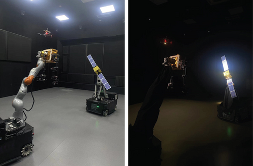
However, there are two issues that these existing systems cannot resolve. On the one hand, during the precontact phase, the large range of spacecraft relative motion may well go beyond two manipulators that are fixed on the ground or on a rail. On the other hand, space missions are sometimes not limited to two objects, and the service satellite could release a third assistance satellite for illumination and vision sensing. To address these challenges, we establish a novel indoor system, a large-scale multiobject emulation platform (LMEP), which is based on a mobile serial manipulator, a mobile parallel mechanism, and an unmanned aerial vehicle. This novel hardware configuration makes it possible to simulate the wide-ranging movements of three or more space objects. Figure 1 shows the actual system at runtime.
In this system, trajectory planning is an unsolved problem. For on-ground emulation tasks, the essential issues are safety and precision. First, compared with space, the indoor field has more limitations, such as walls, ceilings, gravity, and hardware kinetic limits. Complicated multiobject relative motion in space includes precession, circling, and approaching nonlinearly, and it cannot be reproduced on-ground directly. The existing robot planning methods cannot solve this problem; it is more like a mapping process. Therefore, we need a mapping method to find feasible end-effector trajectories for the indoor robot end effectors. To our knowledge, this problem has rarely been addressed. Second, a novel joint trajectory planning method for mobile robot joints is required in our system. Although mobile platforms can enlarge the kinetic emulation range of manipulators, they also introduce inaccuracy. In the control part, the manipulators compensate for the mobile base’s pose error in real time. To realize it, the trajectory must ensure that manipulators have the freedom to compensate for slight pose errors without reaching singularities or boundaries. The constraints mentioned above make planning for the LMEP difficult.
Although there are several studies on planning for mobile manipulators, most mainly involve the problem of motion coordination between the base and manipulator. Hu et al. and Janiak and Tchoń analyzed the motion planning of mobile manipulators from the perspective of kinematics modeling [22, 23]. Oriolo et al. proposed a coordinated planning framework for mobile manipulators to move along a given end-effector path [24, 25]. Wang et al. proposed a task planner for painting tasks [26]. Burget et al. combined an informed rapidly exploring random tree star (RRT ∗) and bidirectional RRT into a new sampling-based algorithm named bidirectional informed rapidly-exploring random tree star (BI2RRT ∗) and considered task constraints when planning mobile manipulator paths [27]. These planning methods mainly address motion in a sophisticated map that is scattered with different obstacles and do not consider precision compensation, which is essential in an LMEP.
In this paper, we analyze the kinetic configuration of the system, simplify the redundant degrees of freedom (DOF), and decouple the horizontal and vertical constraints. Then, the optimal trajectories of all the objects are found to ensure safety and smoothness. For the joint trajectories of mobile manipulators, we propose a cost function based on manipulability and the singularity coefficient to optimize the trajectories of mobile bases. Our methods of trajectory mapping and planning can be applied to other kinetic emulation platforms based on different numbers of mobile manipulators.
The remainder of this paper is organized as follows. Section 2 describes the composition and implementation of the LMEP hardware and software. Section 3 establishes the abstract kinematic model of the LMEP and analyzes the different parts of the workspace. In Section 4, the trajectory planning algorithm is presented in detail. Section 5 describes the demonstration experiments and provides a discussion. Conclusions are given in Section 6.
2. LMEP System Description
2.1. Hardware Overview
- 1.
Target satellite motion simulator. The satellite model is heavy for its authentic appearance, and its type of motion is tumbling. Serial manipulators are not suitable. The Stewart parallel mechanism combined with a rotational joint makes it possible to simulate satellite precession. The omnidirectional mobile base enlarges the motion range. Inner sensors measure the linkage displacement of the parallel mechanism in validation experiments. It is powered by batteries in the mobile base, and it can work continuously over 2 h.
- 2.
Service satellite motion simulator. A 7-DOF KUKA manipulator is mounted on an omnidirectional mobile base. Joints’ angle sensors are used to show experimental results. The service satellite has an additional joint for rotation. Cameras, manipulators, a microcomputer, a Jetson TX2, and other tools are used to validate the vision-based and control algorithms. Unlike the target satellite, the service satellite’s attitude varies slowly, while its position changes fast in the missions. The redundant serial manipulator is more suitable in this case. Its power type and endurance are similar to the target satellite motion simulator.
- 3.
Assistance satellite motion simulator. This is a DJI drone equipped with a camera and a searchlight. As the third object, the drone rather than mobile manipulators can make full use of the indoor space and enlarge the emulation range. The drone can work for about 25 min, after which a second battery is needed.
- 4.
Sunlight emulator. This device can produce parallel circular light. Its radius is 0.7 m, which is sufficient to cover the target area. The light’s direction and intensity are changeable. To simulate space conditions, all walls are covered with light-absorbing material.
- 5.
Motion capture system. Twelve fixed infrared cameras can track the pose of any rigid body in the field. A rigid body is made up of multiple reflective markers on mobile bases or on the drone. Its measurement frequency is set at 100 Hz. Its 3D precision of a single reflector is ±0.1 mm. In real time, the pose data of the measured objects is transmitted to the central control system.
- 6.
Central control system. Trace planning, state monitoring, and human–computer interaction are implemented on these servers.
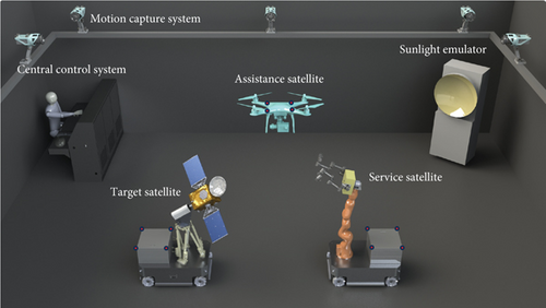
Different types of robots are involved in the LMEP, namely, omnidirectional mobile bases, a serial manipulator, a parallel manipulator, and a drone. Notably, they have different precisions. The position precisions of the serial manipulator and the parallel manipulator are less than ±1 mm. However, the position precision of the mobile base is as large as ±5 cm. To solve the problem of poor precision of the bases, we use manipulators to compensate for the pose error. Hence, trajectory planning for this kind of system is crucial.
2.2. Software Overview
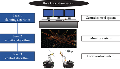
For the software, we implement three control systems at different levels, and all of them are implemented under the framework of the Robot Operating System (ROS) [28]. Figure 3 shows the software composition. At Level 3, the local control system controls the robot joints in real time, including the mobile bases, manipulators, and drones. At Level 2, the monitoring system acquires all the robot state poses and state information, provides control feedback in pose, and ensures system safety at runtime. In Level 1, the central control system plans robot trajectories according to real trajectories in space missions. The trajectory must meet two requirements: (1) The real space trajectory is well mapped to the indoor environment without potential collisions. (2) The trajectory of the mobile manipulator is suitable for precision compensation without reaching limits or singularities. In the following chapters, we describe the planning algorithm.
3. Kinematic Modeling and Workspace Analysis
3.1. Kinematic Modeling of LMEP
Four important coordinate systems in the LMEP are defined in Figure 4, including the world coordinate system and the coordinate systems of the three objects. During on-ground emulation, we assume that the relative poses of the space objects are known and that the pose of one object determines the others. We set the target satellite, which is the mobile parallel mechanism’s end effector, as the baseline. During trajectory mapping, the poses need to be determined for the safety and feasibility of the kinetic emulation.
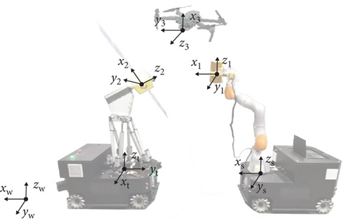
Since the three mobile robots have different configurations, to achieve trajectory mapping, we first need to determine the reachable poses of objects.
The assistance satellite, a drone with a camera gimbal, can reach most poses at a sufficient distance from the walls.
For the service satellite, the workspace of the manipulator is limited. Searching all poses in six dimensions is difficult and unnecessary in our system because we find that some simplifications can be made. The mobile base provides three DOF, and the last rotational joint provides rolling movement. Only two dimensions, height h2 and angle θ2, are limited by the manipulator.
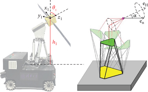
Similarly, for the target satellite, the mobile base and the rotational joint provide for DOF. The parallel mechanism structure determines the range of height h1 and angle θ1. In this way, we reduce the number of searching dimensions to 2. Notably, z1 is not fixed to the target satellite but instead represents the precession axis, which will be introduced in Section 3.3.
3.2. Workspace Analysis for the Service Satellite
As Figure 5 shows, the serial manipulator configuration is spherical–revolute–spherical, analogous to that of a human shoulder–elbow–wrist [29]. This configuration can decouple the orientation and position of the end effector. Due to the redundant DOF, the elbow can move along a redundancy circle without changing the pose of the end effector. The analytic solution of inverse kinematics can be found as long as the phase angle of the redundancy circle is given.
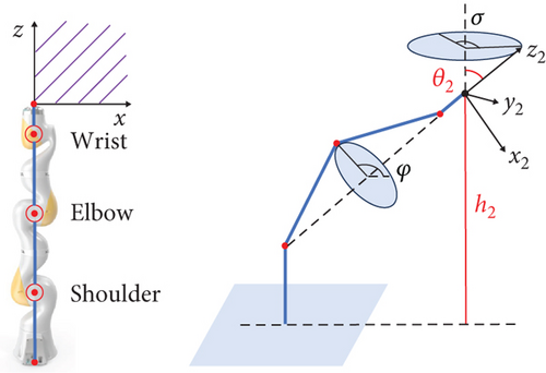
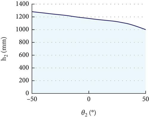
To determine the range of heights h2 and angles θ2, checking all potential poses in six dimensions is expensive. Considering the rotational symmetry around the base joint, we can merely search for poses with positions in the x-z plane. In addition, the last joint of the wrist itself controls the rolling angle. Thus, we only care about the yaw angle, as shown in Figure 5. We search for possible h2 and θ2 values in five dimensions (h2, θ2, φ, α, and x2). The results are shown in Figure 6. For an angle of [−50, 50] degrees, a height h2 of [0, 1000] mm is always feasible.
3.3. Workspace Analysis of the Target Satellite
The angle α between two vectors is the precession angle. The parallel mechanism is suitable for precession emulation because it is precise and stable and can carry heavy models. If the noncooperative target is not axially symmetrical, its motion would be nutation, similar to precession but more complicated. At present, space missions rarely aim at these targets. Actually, the parallel mechanism can emulate nutation, and at present, emulating precession meets the practical needs.
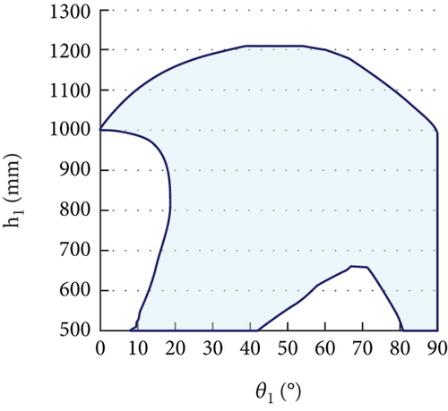
Figure 7 shows how the parallel mechanism simulates precession. The coordinate system (x1, y1, z1) is not fixed to the satellite; it represents the mass center position and the precession axis orientation. The mass center of the satellite remains in the field, and the parallel mechanism pose is calculated according to the precession motion. For a certain precession angle, we need to determine the available range of parameters (h1, θ1). The mobile base provides two additional DOF, which enlarge the range of the emulation. Therefore, for a certain (θ1, h1), we search in two horizontal dimensions and check whether all discrete poses of the end are feasible. Taking a precession angle of 30° as an example, the target satellite workspace is shown in Figure 8. For angle θ1 in [0, 90], the height h1 has a different range.
4. Hierarchical Trajectory Planning for Precise Control
In this chapter, we solve the trajectory planning problem. First, based on the kinematic modeling and analysis above, we map the space trajectories of the three objects to our on-ground system, and the results need to be collision-free and smooth. Then, we propose a method for planning the joint trajectories of redundant mobile manipulators. We optimize the trajectories by considering manipulability, singularity, and smoothness. The planning results are the foundation of the precise control of the mobile manipulators.
To demonstrate the process of trajectory planning and validate the feasibility of the results, we design a potential space task, which is based on future space missions. In this task, the target satellite is defunct and tumbling. The service satellite with powerful computational resources, manipulators, sensers, and tools aims to approach and handle it. The assistance satellite is supposed to enhance the light condition and provide more visual sensing so that the service satellite can make better decisions and accomplish more difficult missions.
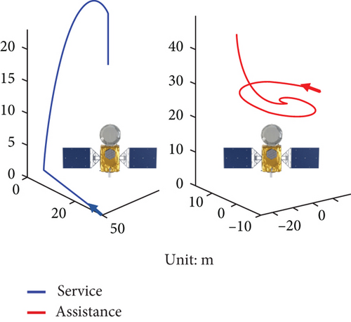
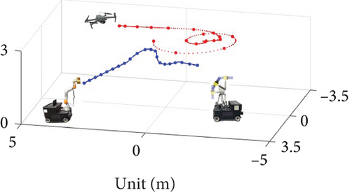
Specifically, the precession angle of the target satellite is 30°. The relative motion of the service satellite and the assistance satellite are shown in Figure 9. The target satellite is set at the origin. The antenna is defined as the top of the target satellite. The service satellite first starts approaching at a distance of 60 m, then turns above the target satellite, and finally arrives at a distance of 6 m. The assisting satellite first hovers over the target satellite and then moves to one side to cooperate with the service satellite. During the task, both satellites face the target satellite. The whole process lasts 240 s. For brevity, the trajectory formulas are not shown here in detail. The relative spatial trajectories are simulated on the ground with a reduction ratio of 10.
4.1. Trajectory Mapping of Multiple Space Objects
Although the mobile robots in the LMEP make it possible to simulate large-scale and complicated motions on the ground, how to realize these motions safely and precisely still needs to be determined. We propose a hierarchical method that includes two steps: space trajectory mapping and dynamic planning for mobile manipulators. In the first step, we decouple the horizontal and vertical constraints to determine the feasible parameter range and generate the optimal trajectory of the target satellite via the LMEP.
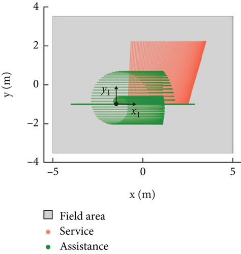
As discussed before, the parallel mechanism pose, represented by height h1, angle θ1, and horizontal coordinates (x1, y1), determines the poses of the other robots. Among these parameters, the horizontal coordinates and angle θ1 are related to the horizontal limits of the indoor field, and the height and angle θ1 are related to the vertical limits of the field; therefore, we decouple them to decrease the computations. All the angle θ1 values are enumerated, and the possible horizontal positions of the two satellites are plotted in Figure 10. In this way, we can put (x1, y1) at (−1, −1.5 m), which is proven to be safe and reliable.
Next, we consider the vertical limits and generate on-ground trajectories. According to kinetic modeling, the on-ground trajectories depend on the target satellite’s pose parameters (θ1, h1). We propose algorithms to find a feasible range of (θ1, h1) and generate an optimal trajectory. A brief overview of our algorithm is provided in Algorithm 1. For every discrete time, we calculate the three objects’ poses according to all possible (θ1, h1) in the workspace of the target satellite. We determine whether the poses belong to the service satellite and the assistance satellite’s workspace. If no collision occurs, the parameters (t, θ1, h1) are recorded as potential trajectory points.
-
Algorithm 1: Searching of the feasible range.
-
1: for t in [1 : 240]
-
2: for (θ, h) in WS_target
-
3:
-
4:
-
5: if Tservice in WS_service&Tassist in WS_assist
-
6: (t, h1, θ1) is recorded
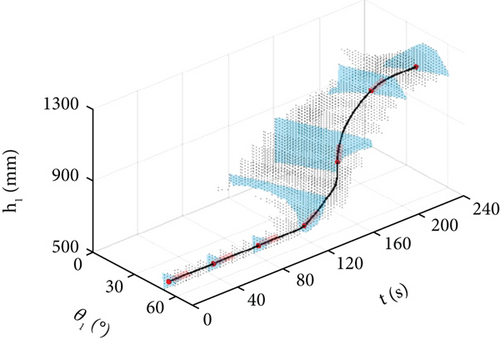
The feasible pose parameter range of duration is plotted in Figure 11. Since the gradient of (θ1, h1) determines the change rate of the service satellite’s height, the optimal trajectory should have the least gradient at all times. In our algorithm, we first ensure that all trajectory points are away from the boundary. From the start time, we fix a cylinder to the current point. The cylinder length is 10, which represents 10 s of following time. Its radius is the necessary distance away from the boundary, which is set to 3. We search for the best orientation of the cylinder that does not cross the boundary and has the least slope and then calculate the next trajectory point. This process is also shown in Figure 11, and a brief overview of the algorithm is shown in Algorithm 2.
-
Algorithm 2: Generation of the optimal trajectory.
-
1: for t in [1 : 240]
-
2:
-
3:
-
4:
The actual trajectories of the three objects in the LMEP are shown in Figure 12. We can see that although our on-ground system has many more constraints than space, redundant DOF is used to map the space trajectories. The trajectory is optimal in terms of safety, feasibility, and gradient.
4.2. Feasibility-Based Trajectory Planning Method
Now that the trajectories of the objects are obtained, we need to plan a joint trajectory for the precise control of mobile manipulators. For both the mobile serial manipulator and the mobile parallel manipulator, we aim to ensure safety and maintain more space for the manipulator to compensate for the pose error of the mobile bases.
We propose a planning method based on a feasibility function. For every trajectory point T(ti) i = (1 ⋯ N), we find a proper position for the mobile platform, where the manipulator is highly manipulable and away from singularities. In this way, the manipulators can be controlled to compensate for the movement errors of mobile platforms.
Manipulability ξ implies the size of the reachable space around a manipulator’s current configuration. In our case, q is the manipulator’s configuration, (l1, l2, l3, l4, l5, l6) is the parallel manipulator, (θ1, θ2, θ3, θ4, θ5, θ6, θ7) is the serial manipulator, and J(q) is the Jacobian matrix.
Furthermore, we set the singularity avoidance coefficient ψ(q), which represents the shortest distance to singularities or boundaries within the feasible area in the x-y plane.
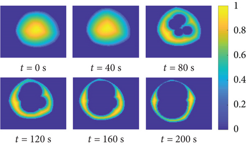
Ff evaluates the feasibility of the manipulator’s configuration, and its value range is [0, 1]. The larger the Ff is, the more feasible the configuration is. k and n are the adjustment factors, and we set k = 0.3, n = 2 empirically. ξmax and ψmax are the maximum values to normalize ξ(q) and ψ(q). This method is designed for mobile manipulators and suits both the service satellite and the target satellite. Here, we take the mobile parallel manipulator as an example. Figure 13 shows the distribution of Ff in the x-y plane for the trajectory of the target satellite. The vertical axis ranges from −500 to 500 mm, and the horizontal axis ranges from −800 to 500 mm.
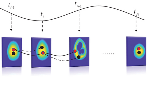
For each step ti+1, we dynamically obtain the optimal [xi+1, yi+1] on the basis of the past trajectory points. Figure 14 shows the dynamic planning process; the red points represent the actual results, and the black points represent the results without optimization.
5. Experiment Results and Analysis
To demonstrate our planning method, we construct actual experiments in our system. The space trajectory we simulate is shown above, which is complicated and representative. The target satellite is assumed to be uncontrolled and tumbling, the service satellite and the assistance satellite gradually approach each other, and the whole process is divided into different phases.
Based on the proposed method, we first map the satellite trajectories to the indoor system and then plan joint trajectories for the mobile robots using our feasibility-based dynamic planning method. During the control process, the pose error of the mobile bases is monitored by the motion capture system and fed back by the high-precession manipulators in real time. The experimental results are shown below.
It should be mentioned that, in this experiment, the space trajectories are given previously and the planning algorithm is executed before emulation. But the system has the ability of real-time planning when the space mission is about closed-loop operations or space-ground synchronization. During emulation, the motion capture system’s data is transmitted to the mobile robots’ controllers through ROS so that the feedback control can be executed in real time.
Figure 15 shows the planned trajectory of the mobile base of the target satellite. The movement error of the mobile base is 5 cm.
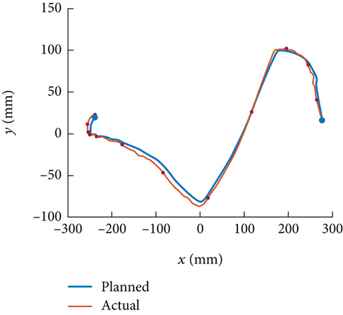
Figure 16 shows the pose error of the target satellite without feedback control. The errors in x and y are as large as several centimeters, and the error in the roll angle is approximately 2°, but the errors in the other dimensions are very low (±4 mm in z, ±0.2° in Euler angles). This proves that the pose precision is significantly affected by horizontal errors, which are inevitably caused by the mobile base. The situation is the same as that of the service satellite; for brevity, the service satellite pose data are not shown here.
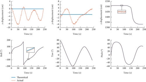
Finally, we conduct an emulation experiment with manipulator feedback in pose. In this case, the horizontal control error of the satellite is reduced to ±4 mm, which is the same as that of z. During the whole emulation process, the mobile robots and the drone execute the trajectory safely and smoothly, and collision or singularity does not occur. The experiment shows the feasibility of our trajectory planning method.
This system would be the testbed for vision-based reconstruction, navigation, and many closed-loop operations. Though there are many researches in this area, they still suffer from poor light conditions, the target satellites’ complicated motion, and other effects [33, 34]. We are trying to solve these problems and validate new methods in LMEP.
6. Conclusion
We built an on-ground emulation platform (LMEP) based on mobile manipulators and a drone to simulate the large-scale motion of multiple satellites. The goal was to simulate complicated space trajectories indoors safely in a manner suitable for high-precession feedback control. We first analyzed the system kinetics and simplified a hyper-redundant system. Then, we analyzed the workspace of two kinds of mobile manipulators, which were used to map the trajectories to the on-ground field. Next, we proposed a dynamic planning method based on the feasibility of mobile manipulators, which ensured that the joint trajectories of the manipulators were suitable for feedback control without collision or singularity. The experimental results showed that our LMEP system can simulate multiple objects and complicated movements in space precisely and safely.
Conflicts of Interest
The authors declare no conflicts of interest.
Funding
This research was supported by the National Natural Science Foundation of China under Grant 5195308.
Acknowledgments
This research was supported by the National Natural Science Foundation of China under Grant 5195308.
Open Research
Data Availability Statement
The data that support the findings of this study are available from the corresponding author upon reasonable request.


